Jack PC EFI Series Hardware User Manual Revision C 06/06/2006 *CDC01927* 1
Jack PC Hardware User Manual - Training Department Revision C 0506 COPYRIGHT NOTICE © 2006 Chip PC Inc., Chip PC (Israel) Ltd., Chip PC (UK) Ltd. All rights reserved. This manual and the software and hardware described herein, in whole or in part, may not be reproduced, translated, or reduced to any machine-readable form without prior written approval.
Jack PC Hardware User Manual - Training Department Revision C 0506 TABLE OF CONTENT 1 SAFETY NOTICES ............................................................................................................................................................4 1.1 2 2.1 2.2 2.3 2.4 3 Safety Instructions............................................................................................................... 5 INTRODUCTION..............................................................................
Jack PC Hardware User Manual - Training Department Revision C 0506 Welcome and congratulations on your purchase of the Jack PC! This User Manual contains the information you will need in order to set up your Jack PC's hardware. For information concerning the Jack-PC's software aspects, please refer to the Software User Manuals, that can be found at www.chippc.com 1 SAFETY NOTICES This section contains important safety notices.
Jack PC Hardware User Manual - Training Department Revision C 0506 1.1 Safety Instructions Please read the following safety instructions carefully before using the product: • • • • • • Be sure not to expose the product to excessive humidity. When using an external power supply, place the DC power cord in such a way to avoid people stepping on it.
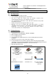
Jack PC Hardware User Manual - Training Department Revision C 0506 2 INTRODUCTION The Jack PC is a versatile, feature-rich thin client computer fully integrated into an existing LAN Jack, it is the most secure, modular, and manageable Thin-Client solution offering connection to any type of popular Terminal, Citrix or Legacy servers. With the Jack PC, you can quickly and easily convert an existing enterprise LAN jack into a fullyworking, remotely-managed computer without installing additional cabling.
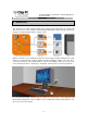
Jack PC Hardware User Manual - Training Department Revision C 0506 The Jack PC can be fitted into wall, floor or furniture housing according to site specific needs. Installation is easy and quick and enables an organization-wide usage of LAN Jacks for various uses offered by the Flex-Jack system (see www.chippc.com for more details about additional Flex-Jack devices). The Jack PC is secured inside the wall and behind the faceplate, eliminating exposure to damage, disconnection or theft.
Jack PC Hardware User Manual - Training Department Revision C 0506 2.1 Power Options Power-over-Ethernet (PoE) becomes a common technology as many sites adding PoE to support VOIP telephony and wireless access points. Jack PC devices are especially built to be powered by Power-over-Ethernet infrastructure. However, where there is no PoE switch available, Jack PCs can be powered through a Midspan injector or with the external power supply supplied by Chip PC.
Jack PC Hardware User Manual - Training Department Revision C 0506 2.2 Intended Audience This User Manual is primarily intended for IT staff and administrators, though end-users and others might find it helpful as well. 2.3 Main Topics Overview This User Manual covers the hardware aspects of your new Jack PC, including hardware setup and installation, wiring and network configuration, troubleshooting etc.
Jack PC Hardware User Manual - Training Department Version 0506 3 HARDWARE SETUP 3.1 Site Preparation Before installing the Jack PC make sure that: 3.2 • The site wiring is appropriate (power and network). • The site is away from devices that can generate electrical noise, electromagnetic interference, heat, vibration and such. • The environmental requirements of the Jack PC as defined in the product specifications are met.
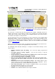
Jack PC Hardware User Manual - Training Department Version 0506 3.3 Identifying the Parts of the Jack-PC Model EFI-6700 and 6800 Jack-PC Parts & I/O Ports 4 USB 2.0-compatible ports that can be used for: • Standard USB keyboard* including most wireless models • Standard USB mouse* including most wireless models • USB printers* • External USB PC/SC Smart Card Reader • External mass-storage devices, such as USB Flash Key, CD, Floppy, DVD, Camera etc.
Jack PC Hardware User Manual - Training Department Version 0506 3.4 Existing LAN Installation Tools you will need for Existing Jack Installation: 1 • Power-over-Ethernet Tester (where PoE is available (see power options 1 and 2 in the introduction chapter) – it is recommended to verify that the LAN jack receives power with this tester) - this is an optional accessory that you need to purchase separately (Chip PC part number: CPN02239 – see accessories list).
Jack PC Hardware User Manual - Training Department Version 0506 5 Insert the RJ-45 Termination Connector Block into the Flex-Jack Housing bottom part until you hear a clicking sound indicating it has locked properly into place. 6 Place the Flex-Jack Housing inside the Jack hole. Trim wall cutout if necessary. 7 Test the Flex-Jack has current before you continue.
Jack PC Hardware User Manual - Training Department Version 0506 9 The Jack PC device should be inserted with the contacts (shown in the picture) facing downwards, as shown in the picture. 10 Insert the Jack PC device into the Housing until you hear a clicking sound indicating the device has locked properly into place. Verify device locking by gently pulling device outwards.
Jack PC Hardware User Manual - Training Department Version 0506 12a Model EFI-6900 offers dual-screen support. In order to get this functionality, connect a Y-cable to the DVI monitor port. Purchase the Y-cable only from Chip PC to assure compatibility. (Chip PC part number: CPN02176 - see accessories list). In order to connect only one VGA monitor, you will need to use Chip PC DVI to VGA adapter. Purchase the DVI to VGA adapter only from Chip PC to assure compatibility.
Jack PC Hardware User Manual - Training Department Version 0506 3.5 New Installation Tools you will need for New Installation: • Drill with 65 mm (2.
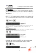
Jack PC Hardware User Manual - Training Department Version 0506 3 Trim the cut out gently and check that the housing fits in properly. 4 Pull out the LAN cable and remove 4 cm/1.5 inch of its plastic insulation. Separate wire pairs by color and roll the shielding wires together. 5 Open the IDC Termination Connector Block red cover. Secure the wires with an Corona PunchDown Tool by using the appropriate color scheme, according to TIA568 version A or B as shown in picture.
Jack PC Hardware User Manual - Training Department Version 0506 6 Close the IDC Termination Connector Block and insert it into the Housing bottom part until you hear a clicking sound indicating it has locked properly into place. In case the Connector Block in not locked in to position, you can slightly bend the metal tab to create more pressure on the Connector Block.
Jack PC Hardware User Manual - Training Department Version 0506 9 Test the Flex-Jack has current before you continue. The Jack PC device should be inserted with the contacts (shown in the picture) facing downwards, as shown in the picture. 10 Insert the Jack PC device into the Housing until you hear a clicking sound indicating the device has locked properly into place. Verify device locking by gently pulling device outwards.
Jack PC Hardware User Manual - Training Department Version 0506 12a Model EFI-6900 offers dual-screen support. In order to get this functionality, connect a Y-cable to the DVI monitor port. Purchase the Y-cable only from Chip PC to assure compatibility. (Chip PC part number: CPN02176 - see accessories list). In order to connect only one VGA monitor, you will need to use Chip PC DVI to VGA adapter. Purchase the DVI to VGA adapter only from Chip PC to assure compatibility.
Jack PC Hardware User Manual - Training Department Version 0506 3.6 Connecting the Cables See section 3.3. for a complete overview of all connectors of your Jack PC device. Connect USB peripheral device (USB keyboard, mouse, printer etc.) to a USB port. Note: USB devices may be connected after product being powered although some devices would not work properly due to driver loading problems. In this case, Press the Reset Button and the USB devices will work properly.
Jack PC Hardware User Manual - Training Department Version 0506 3.7 Turning the Jack-PC ON After you have connected all peripherals and cables, follow these steps to turn your Jack PC ON: • In case you have Power-over-Ethernet, the device will get power immediately as you fully insert the Jack PC to the Flex-Jack housing. It will remain powered as long as it is connected to the PoE infrastructure (either to a PoE switch, or to a Midspan power injector).
Jack PC Hardware User Manual - Training Department Version 0506 4 JACK-PC MODELS Jack PC EFI-6700 Jack PC EFI-6800 Jack PC EFI-6900 Oparating System Windows CE .NET 4.2 Windows CE .NET 4.2 Windows CE .NET 4.2 Class Wall-Integrated Wall-Integrated Wall-Integrated CPU AMD Au 1550 RISC AMD Au 1550 RISC AMD Au 1550 RISC CPU FSB 333 MHz 500 MHz 500 MHz Equiv. x86 800 MHz 1.2 GHz 1.
Jack PC Hardware User Manual - Training Department Version 0506 5 JACK-PC SPECIFICATIONS CPU • • Memory Mass Storage Display • • • • • • • EFI 6700 AMD Au 1550 Alchemy processor, 333 MHz RISC (equivalent to 800MHz x86 TC Processors) EFI 6800-6900 AMD Au 1550 Alchemy processor, 500 MHz RISC (equivalent to 1.
Jack PC Hardware User Manual - Training Department Version 0506 Physical Characteristics Environmental • • Dimensions: Jack PC with EU/UK Frame: o 8.60cm/3.44 inch (Width); o 8.60cm/3.44 inch (Height); o 3.95cm/1.58 inch (Depth) Jack PC with US Frame: o 6.96cm/2.78 inch (Width); o 11.40cm/4.56 inch (Height); o 3.95cm/1.58 inch (Depth) Device weight (with frame): 350gr [12 oz] Shipping weight without power supply - 0.42 65 Kg [0.
Jack PC Hardware User Manual - Training Department Version 0506 6 WIRING CONFIGURATIONS 6.1 LAN wiring basics Some facts about the LAN cabling: • The wires inside LAN cables are made of 4 x twisted pairs marked with similar color (i.e. Orange and White-Orange). • For the 10/100 LAN function to work – only 4 wires (2 pairs) are needed as minimum: two RX lines and two TX lines (1 and 2, 3 and 5). • Giga LAN uses all 8 wires in the cable + the shielding.
Jack PC Hardware User Manual - Training Department Version 0506 6.2 LAN wiring color coding In general wire colors are not critical for proper operation as long as wires are connected correctly. There are two wiring codes commonly in use - TIA-568A and TIA-568B. They only differs by the wires color coding as shown in the figure bellow. It is important to note that A and B cables are identical, the only difference between them is how their wires were connected at the ends.
Jack PC Hardware User Manual - Training Department Version 0506 6.3 Non-standard LAN cabling In some cases cable could be a non standard cable or the far end (patch panel) connected in a non-standard way (not in accordance to TIA-568-A or B). In such case you will have to do slightly more work mapping the existing non-standard connections. Please refer to the table bellow. This table should be filled at the far end by looking at the actual connections.
Jack PC Hardware User Manual - Training Department Version 0506 6.4 Testing LAN Cabling In a new installation it is difficult to test the cable before you terminated it with Flex-Jack terminal block. After assembling the terminal block (hopefully in the proper way..) you can use the Jack PC as a tester.
Jack PC Hardware User Manual - Training Department Version 0506 the Jack-PC will consume only 4-6W maximum. Power may vary if demanding USB peripheral devices or dual monitors are attached to the device. Class Usage Minimum Power Levels Output at the PSE Maximum Power Levels at the Powered Device 0 Default 15.4W 0.44 to 12.95W 1 Optional 4.0W 0.44 to 3.84W 2 Optional 7.0W 3.84 to 6.49W 3 Optional 15.4W 6.49 to 12.
Jack PC Hardware User Manual - Training Department Version 0506 6.7 Pre-standard PoE Currenly there is a global standard for Power-over-Ethernet maintained by the IEEE. This standard identified as IEEE 802.3af and is accepted by all vendors. Unfortunately, before it was accepted there were other PoE detection methods that were sold by many vendors. These PoE methods called today pre-standard.
Jack PC Hardware User Manual - Training Department Version 0506 7 7.1 TROUBLESHOOTING Basic Troubleshooting flow Immediately after you fully insert the Jack-PC device into the installed Flex-Jack housing, you sould see the Power/Fail LED illuminated green. After about 30 seconds you should see the Link LED illuminated orange (see figure 7.1). If nothing happens - no lights – use the basic troubleshooting flow below.
Jack PC Hardware User Manual - Training Department Version 0506 7.
Jack PC Hardware User Manual - Training Department Version 0506 Reset To Default Flow Press and hold while holding & press and release Wait for Red light and release Press once (press and release) and immediately press again and hold until the system logs in to safe mode. .
Jack PC Hardware User Manual - Training Department Version 0506 Always start your troubleshooting flow here: Both Link and Power LEDs are OFF Check if the Jack PC is fully inserted to the Flex-Jack Metal Housing Connect external power supply Device failure Contact Chip PC support No Power/Fail LED green? Yes No Link LED lighted (after 30 seconds)? Yes Go to LAN Flow Go to PoE Flow 35
Jack PC Hardware User Manual - Training Department Version 0506 7.3 LAN Troubleshooting flow If power is OK through external power supply but still there is no LINK you should suspect the wiring. The following flow will guide you through the troubleshooting procedure in such a case: Device powered but NO Link LED Check at the far end that the port is connected to the switch Check at the far end if TIA-568-A or B is used Something Else TIA-568? See Figure 6.
Jack PC Hardware User Manual - Training Department Version 0506 Connect at the far end a simple 4 ports LAN switch Switch configuration / port problem Yes Problem resolved? No Check: • That the cable connected is the one you are testing at the far end (might be labeling problem) - check the port is working with another device • The patch panel contacts and labeling • That the Flex-Jack Terminal block contacts are not contaminated.
Jack PC Hardware User Manual - Training Department Version 0506 7.4 PoE Troubleshooting flow If the Jack-PC device is working properly when an external power supply is connected to it, but it is unpowered when connected to PoE capable port without the power supply, we have a PoE problem. See the flow bellow to debug this problem. In geneal the most important thing here is to isolate the cabling and connection components (wiring, Flex-Jack, patch panel) and the power source (power injector or switch).
Jack PC Hardware User Manual - Training Department Version 0506 8 ACCESSORIES LIST For an updated list, and more information, see Chip PC website at: http://www.chippc.com/products/accessories Part Number CPN01804 Name Description Image USB PC/SC Smart Card reader USB PC/SC smart card reader .
Jack PC Hardware User Manual - Training Department Version 0506 CPN02433 DVI to HDMI cable adapter CPN01491 Power Supply wall-mount, EU, 100240VAC, 5VDC, 2.4A Power Supply wall-mount, US, 100240VAC, 5VDC, 2.4A Power Supply wall-mount, UK, 100240VAC, 5VDC, 2.4A CPN01503 CPN01504 DVI to HDMI (High-Definition Multimedia Interface) cable adapter Power Supply wall-mount, EU, 100-240VAC, 5VDC, 2.4A (to be used where PoE is not available) Power Supply wall-mount, US, 100-240VAC, 5VDC, 2.
Jack PC Hardware User Manual - Training Department Version 0506 CPN02248 Corona Punch-Down Tool Corona Punch-Down Tool to connect the network wires to the Flex-Jack Housing CPN02221 PowerDsine Midspan Power-overEthernet (PoE) Injector US (Single Port) PowerDsine Midspan Power-overEthernet (PoE) Injector UK (Single Port) PowerDsine Midspan Injector US (Single Port) to enable single port Power-over-Ethernet (PoE).
Jack PC Hardware User Manual - Training Department Version 0506 CPN02239 PowerDsine PoE Tester PowerDsine PoE Tester, used to identify if PoE exist in the Jack CPN02171 Jack PC Extraction Tool, T-6 Jack PC Extraction Tool, T-6, used to remove an installed Jack PC unit from the Flex-jack Housing CPN02167 Flex-Jack Housing EU/UK Flex-Jack Housing - EU/UK for use with Flex-Jack devices such as Jack PC CPN02168 Flex-Jack Housing - US Flex-Jack Housing - US for use with Flex-Jack product such as Jack
Jack PC Hardware User Manual - Training Department Version 0506 CPN02173 Flex-Jack External Mounting Box - US Flex-Jack External Mounting Box US - to install a Flex-Jack device such as Jack PC externally CPN02431 EU/UK WallSide Frame EU/UK Wall-Side Frame to connect Jack PC with an existing Jack CPN02169 Flex-Jack Legacy, Prestandard CISCO POE module Flex-Jack, Pre-standard CISCO PoE module - enables devices such as Jack PC to work with Prestandard PoE devices.
Jack PC Hardware User Manual - Training Department Version 0506 9 REGULATORY COMPLIANCE This product has been tested and found to comply with the limits of the regulations needed to receive the following marks: • EMI/EMC: FCC Class B; CE Mark; VCCI. • Electrical Safety: UL60950-1; cUL Listing; CE Mark (IEC/EN 60950). • This product is ENERGY STAR labeled and meets the ENERGY STAR guidelines for energy efficiency. 9.
Jack PC Hardware User Manual - Training Department Version 0506 ENVIRONMENTAL & REGULATORY DETAILED INFORMATION A. System Dimensions and Weight Configuration Depth, cm Width, cm Height, cm Weight, kg With decorative frame 3.6 8.6 8.6 0.35 Without decorative frame 3.6 5.8 5.8 0.25 B. Declarations and Certifications B1.
Jack PC Hardware User Manual - Training Department Version 0506 1 C. Performance Data C1. Electromagnetic Compatibility Systems marked with the symbol “CE” indicate compliance to the EMC Directive and the Low Voltage Directive of the European Union. C2. System Configuration The Energy Consumption and Declared Noise Emissions data is based on a device running the highest resolution and color depth setting, in 100BaseT full duplex network with ICA session presenting graphic intensive screen saver.
Jack PC Hardware User Manual - Training Department Version 0506 F. Product materials information F1. Restricted Substances This Chip PC product (plastic case parts, printed wiring boards, power supplies, and microprocessors) does NOT contain any of the following substances (in concentrations exceeding natural background levels) • Asbestos • Cadmium and its compounds above 100 parts per million (ppm) • Halogenated dioxins or furans (i.e.
Jack PC Hardware User Manual - Training Department Version 0506 G. Packaging No CFCs (chlorofluorocarbons), HCFCs (hydrofluorocarbons) or other ozone depleting substances are used in packaging material. Chromium, lead, mercury, or cadmium are not intentionally added to packaging materials and are not present in a cumulative concentration greater than 100 ppm as incidental impurities. Printed user documentation is bleached in a chlorine-free process.
Jack PC Hardware User Manual - Training Department Version 0506 10 CHIP PC LIMITED HARDWARE WARRANTY Chip PC warrants that the Jack PC you have purchased from Chip PC or from an authorized Chip PC reseller is free from defects in material and workmanship under normal use during the Limited Warranty period of 3 years. The warranty period commences on the date of purchase. Your sales receipt showing the date of purchase of the Jack PC is your proof of the date of purchase.
Jack PC Hardware User Manual - Training Department Version 0506 CHIP PC SPECIFICALLY DOES NOT REPRESENT THAT IT WILL BE ABLE TO REPAIR ANY PRODUCT UNDER THIS WARRANTY. U.S.A. State Laws Some states do not allow limitations on how long an implied warranty lasts, or allow the exclusion or limitation of incidental or consequential damages, so the above limitations may not apply to you. This warranty gives you specific legal rights, and you may also have other rights, which vary from state to state.
Jack PC Hardware User Manual - Training Department Version 0506 Limited Warranty Types: Mail-In Coverage The Customer will make the initial service request to the Chip PC Customer Service. If Chip PC determines that a repair is required, the Customer will receive instructions on returning the Product to Chip PC. The customer will return the product in its original package or an equivalent.
Jack PC Hardware User Manual - Training Department Version 0506 11 CHIP PC LIMITED SOFTWARE WARRANTY Chip PC (Israel) Ltd (“Chip PC”) or any of its subsidiaries licensing the Software, if sale is not directly by Chip PC , warrants that commencing from the date of delivery to Customer (but in case of resale by a Chip PC reseller, commencing not more than ninety (90) days after original shipment by Chip PC), and continuing for a period of the longer of (a) ninety (90) days or (b) the period set forth in the
Jack PC Hardware User Manual - Training Department Version 0506 The Warranty and the Software License shall be governed by and construed in accordance with the laws of the State of Israel. If any portion hereof is found to be void or unenforceable, the remaining provisions of the Warranty and the Software License shall remain in full force and effect.
Jack PC Hardware User Manual - Training Department Version 0506 12 CHIP PC SOFTWARE LICENSE AGREEMENT IMPORTANT - READ CAREFULLY BEFORE USING THIS PRODUCT WHICH CONTAINS CHIP PC SOFTWARE AND MAY CONTAIN OTHER CHIP PC INTELLECTUAL PROPERTY. USING THIS PRODUCT INDICATES YOUR ACCEPTANCE OF THE FOLLOWING TERMS AND CONDITIONS.
Jack PC Hardware User Manual - Training Department Version 0506 5. U.S. Government Restricted Rights (Applicable to the US Market Only) The SOFTWARE is provided with RESTRICTED RIGHTS. Use, duplication or disclosure by the Government is subject to restrictions as set forth in subparagraph (c)(1)(ii) of the Rights in Technological Data and computer software clause at DFARS 252.227-7013 or in subparagraphs (c)(1) and (2) of the Commercial Computer Software-Restricted Rights at 8 C.F.R.
Jack PC Hardware User Manual - Training Department Version 0506 13 MICROSOFT END USER LICENSE AGREEMENT (EULA) EULA for Microsoft® Windows® CE Operating System for Windows-based Terminal Devices IMPORTANT - READ CAREFULLY This End User License Agreement (EULA) is a legal agreement between you (either an individual or a single entity) and the manufacturer (MANUFACTURER) of the special purpose computing device (SYSTEM) you acquired which includes certain Microsoft software product(s) installed on the SYSTEM
Jack PC Hardware User Manual - Training Department Version 0506 If MANUFACTURER has not included a back-up copy of the SYSTEM SOFTWARE with the SYSTEM, you may make a single back-up copy of the SYSTEM SOFTWARE. You may use the back-up copy solely for archival purposes. 2.
Jack PC Hardware User Manual - Training Department Version 0506 5. Product Support Product support for the SOFTWARE is not provided by MS, its parent corporation, Microsoft Corporation, or their affiliates or subsidiaries. For product support, please refer to MANUFACTURER’s support number provided in the documentation for the SYSTEM.
Jack PC Hardware User Manual - Training Department Version 0506 MANUFACTURER with a copy of your receipt. This Limited Warranty is void if failure of the SOFTWARE has resulted from accident, abuse, or misapplication. Any replacement SOFTWARE will be warranted for the remainder of the original warranty period or thirty (30) days, whichever is longer.
Jack PC Hardware User Manual - Training Department Version 0506 Appendix A Cisco Catalyst Specific PoE Information This appendix discusses Cisco specific information required in order to connect Jack-PCs to Cisco Catalyst PoE enabled switches. When trying to troubleshoot PoE problem with Cisco Catalyst switch, first check that the switch supports IEEE 802.3af PoE. Some Cisco switches are not capable of supporting this new standard.
Jack PC Hardware User Manual - Training Department Version 0506 powered ports in a rack, the maximum capacity would not reach 240 x 15.4W = 3696W due to power supply and heat dissipation problems. To better manage actual power as opposed to standard maximum power, Cisco came up with intelligent power management features. For example, the Catalyst 4500/6500 series switch has three PoE modes: • Auto PoE interface.