
Computer Hardware User Manual


19
Jack PC Hardware User Manual - Training Department
Version 0506
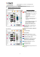
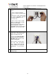
9 Test the Flex-Jack has current
before you continue.
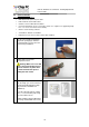
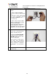
The Jack PC device should be
inserted with the contacts (shown in
the picture) facing downwards, as
shown in the picture.
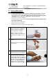
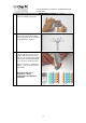
10 Insert the Jack PC device into the
Housing until you hear a clicking
sound indicating the device has
locked properly into place.
Verify device locking by gently
pulling device outwards.
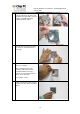
Where using PoE check now to see
that the Power/Fail LED is
illuminated in green, and that the
Link LED is lighted if not use the
troubleshooting guide.
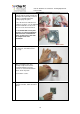
If the device is not locked, remove
the unit, and make sure that the latch
locking hole is intact and is free from
foreign objects. If you are still unable
to lock the unit, try using a different
Metal Housing.
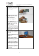
12 Connect Keyboard, Mouse, Monitor
and any other required peripheral to
device ports.
For additional instructions on how to
connect your peripheral devices, see
paragraph 3.6.
Note: In case a USB-to-PS/2
converter or USB-to single/dual
Serial ports adapter (to support serial
printers) is needed (Chip PC part
number: CPN01487).
You can connect the Jack PC to a
Wireless network using the Wireless
LAN USB dongle 802.11g (Chip PC
part number: CPN02302).
Purchase all accessories only from
Chip PC to assure compatibility, for
more details please see the
accessories list.