Chloride Linear Plus Rack-Mount UPS User Instruction Manual IMPORTANT SAFETY INSTRUCTIONS SAVE THESE INSTRUCTIONS. This manual contains important instructions for models: • LP061XHR • LP101XHR • LPBP100-2 Follow these instructions during the unpacking, installation, and maintenance of the UPS. If you have a problem with the UPS, please refer to this manual before calling technical services.
Introduction ......................................................................................................................................................................................... 1 Registering Your UPS ......................................................................................................................................................................... 1 Technical Support ....................................................................................................
ii
Introduction Introduction Thank you for selecting this uninterruptible power supply (UPS). Chloride’s Linear Plus Rack-mount Series UPS offers the most reliable protection from the harmful effects of electrical line disturbances for your computing and communications equipment. Chloride’s ISO 9001 certification represents our commitment to building world-class products. We take pride in every unit that leaves our facility.
Safety • The User or Operator may intervene in the operation of the UPS provided that the instructions laid out in “Batteries” on page 3, “Control Panel for the Linear Plus Rack-mount” on page 16 and “Indication and Operating Elements Linear Plus Rack-mount” on page 15 are strictly adhered to. • The “Installation” of the UPS, described in “Installation” on page 7, may only be carried out by qualified technical personnel.
Safety Emergency WARNING: The supply to the load may be interrupted by opening all the switches. WARNING: DO NOT USE WATER to extinguish any fires that may occur in the area in which the UPS is installed. Leakage Currents WARNING: Connect the earth ground [protection earth (PE)] safety conductor before any other cables are connected. Radio Interference Linear Plus Rack-mount is a class A product. The UPS device may cause radio interference.
About the Operating Instructions Conformity is established through compliance with the following standards: • EN 62040-1-1 • EN 62040-2 Additional information regarding adherence to these directives is included in the appendices NSR and EMC of the EU Declaration of Conformity. If required, the EU Declaration of Conformity can be requested from Chloride.
Preparation for Use Unpacking The utmost care shall be taken when removing the packaging in order to avoid damaging the equipment. Check all packaging materials to ensure that no items are discarded. Remove the packaging following the sequence illustrated in Fig. 1. TOOLS KIT PALLET JACK SCISSORS SCREWDRIVER Fig. 1: Unpacking Storage If it is not intended that the UPS be used immediately upon delivery, attention shall be paid to the storage conditions.
Preparation for Use Inventory list • Parallelable UPS types are equipped with (1) control cable, 25-pin (1) jumper for terminals S1-S2 • Linear Plus Rack-mount UPS contains (1) jumper for disabling the EPO circuit when not in use. • Battery cabinets/racks contain (1) DC-power cable • Linear Plus Rack-mount devices are equipped with (1) set of rails and rail guides (Fig.
Installation 2. Position the left and right rail guides in the four-post rack and tighten all fasteners. CAUTION: The rail guide for the lowest battery cabinet should be installed first at the lowest position in the rack. Once the first battery is installed, then subsequent battery rail guides should be installed above. The final rail guide assembly, located above the last battery cabinet, should support the UPS cabinet at the top. 3. Using Fig.
Installation Installation Data Table 3. Environment data Ambient temperature +32°F to +104°F (0 °C to +40 °C) Relative humidity (w/o condensing at 20°C) 90% Max. altitude (w/o derating) 1000 m a.s.l. Cable inlet bottom at the rear side Air inlet front Air outlet rear Table 4.
Installation inearP Table 5. Mechanical data Linear Plus Rack-mount 6 kVA/10 kVA UPS-TYPE Linear Plus Rack-mount 6 kVA Linear Plus Rack-mount 10 kVA 53 (24) 57 (26) Mechanical Data Net Weight - lbs (kg) Dimensions - in (mm) UPS Width 19 (482.6) Height 5.125 (130) Depth 28.1 (715) Dimensions - in (mm) Body dimensions Width 16.1 (410) Height 5.
Installation conduits or that shielded cables be used. Routing of cables (e.g. power supplies, communication or data lines) to other equipment, should be kept separate from that of UPS cables. Neutral Connection The installation of the UPS does not affect the existing Neutral system. The Neutral system may be affected if the UPS is operating with the Neutral switched upstream. External Protection and Isolating Devices WARNING: A disconnect switch shall be provided by others for AC input/output circuit.
Installation Terminal Blocks for UPS The following figures show the units with the external battery extension. To connect the external battery to the UPS, plug the battery cable (16) into the socket (9) and into a battery extension socket (13). 12 14 | o 16 13 15 16 Fig. 5: Rear View Linear Plus Rack-mount UPS (top), Battery (center), and Cable (bottom) Legend: 1. Output socket(s) IEC 320 - C19 11. Mains connection, Terminal Block 2. 2 Output circuit breaker (for plugged outlets) 12.
Installation extension is connected to the battery connection the UPS (9), each subsequent extension is connected by means of the battery extension connection cables (16). The cables are designed to be non-interchangeable, because the sockets (13) are coded. Connecting Mains Connect the mains supply to the input terminals of the UPS (see Fig. 5 on page 11 and Table 6 on page 9). Connecting parallel UPS configurations: refer to chapter “Paralleling UPS Devices” on page 19. Connecting Load Cables 1.
Operating the Device Auxiliary Backfeed Protection To support protection against UPS backfeeding logic is integrated into Linear Plus Rack-mount. Using backfeed protection On customers side an additional magnetic contactor (MC) may be provided. The magnetic contactor must be able to carry the UPS input current (see tableTable 4, “Electrical data Linear Plus Rack-mount 6 kVA/ 10 kVA,” on page 8). The MC has to be installed in the common input supply path.
Operating the Device Automatic bypass Mains Rectifier/ Booster S 2 1 ESD L Mains S Inverter L LN LN UPS rack Charger Battery fuse b lo c k _ L in + _ E _ r a c k .d s f Battery rack Battery fuse Battery rack External battery 6 k V A /1 0 k V A R A C K Fig. 7: Overview of components Linear Plus Rack-mount 6 kVA/10 kVA Preliminary controls Before switching on the UPS and supplying the load the following shall be observed: • Ensure that the ventilation grilles are unobstructed.
Operating the Device 6. Close any external switches connecting the load (if present). 7. Press the button on the UPS control panel for a minimum of 1 second to switch on the inverter (see “Control Panel for the Linear Plus Rack-mount” on page 16). In addition to the “LINE” and “BYPASS” LEDs the “LOAD” LED and “BATTERY” LED is now illuminated. After a few seconds the “INVERTER” LED is illuminated and the “BYPASS” LED is extinguished. The UPS is now in ON-LINE operation.
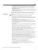
Operating the Device Indication and Operating Elements Control Panel for the Linear Plus Rack-mount 4 7 6 2 1 3 5 The OVERLOAD indicator, red, (1) illuminates if the UPS is overloaded. The LOAD LED strip (2) displays the load status of the UPS. See Table 8 on page 17 for details. The BYPASS indicator, yellow, (3) illuminates when the UPS delivers voltage supplied from the mains supply via the bypass. The INVERTER indicator, green, (4) illuminates when the inverter is running.
Operating the Device The situation can better be analyzed by using the UPS load LEDs, which indicate the remaining autonomy for a constant load. The following table shows the approximate autonomies in case of a fully charged battery at the beginning of the mains failure. Table 8.
Operating the Device The loads are supplied directly from mains via the inverter. Loads are protected against mains failures and disturbances. Battery operation (mains failure) Fig. 10: UPS Control Panel: “Battery Operation” In the event of a mains failure, the inverter supplies the loads without interruption; the power is supplied by the battery. In this operating mode, an acoustical sound is emitted at intervals of approximately 4 seconds.
Operating the Device Emergency Power Off (ESD hardwired) This Linear Plus Rack-mount UPS is equipped with separate terminals for connecting hardwired customer protection ESD relays. See block diagram Fig. 7 on page 14 for connection details. Paralleling UPS Devices A maximum of 3 Linear Plus Rack-mount UPSs can be connected in parallel. The units to be connected in parallel must be of the same type and rating and the settings of these devices must be identical.
Operating the Device 3. Connect the UPS output terminals to the load distribution. S2 S1 Mains Power Distribution Cb #1 UPS #1 Remove Optional jumper Individual Output s1s2 Circuit Breakers Load Distribution L Cb L/N L L/N Parallel Connector S2 S1 Parallel cable #1 UPS #2 L Cb #2 L/N Remove jumper s1s2 L Cb L/N Parallel Connector S2 S1 L Cb #3 L/N Parallel cable #2 UPS #3 L L/N Remove jumper s1s2 Cb Parallel Connector Fig. 12: Linear Plus Parallel Diagram Third step 1.
Maintenance NOTE: In a parallel system, on the unit that has been requested to transfer from bypass to on-line operation (steps 4 and 5), the battery display will pulse illuminate from right to left and the load display will pulse illuminate from left to right. This indicates the system is waiting for the other UPS system synchronize to the first unit. It is critical that after pushing the “ |” button on the first UPS that the second/ third Unit(s) also follows within 1 minute of starting the first UPS.
Interfaces • Do not lay tools or metal parts on top of batteries • Disconnect charging source prior to connecting or disconnecting battery terminals • Determine if the battery in inadvertently grounded. If inadvertently grounded, remove source from the ground. Contact with any part of a grounded battery can result in electrical shock.
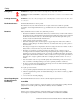
Interfaces R x D ! T x D " % & ' $ S G N # C O M 3 L in e a r P lu s Fig. 13: Serial interface COM 3 The interface COM 3 is galvanically isolated from primary UPS circuits. SGN at pin 5 Signal ground. RXD at pin 2 and TXD at pin 3 Receive and transmit RS 232 compatible signals.
Interfaces Optional Isolated Contacts Card Below are the descriptions of the interface signals for the isolated contacts card that may be installed into the COM slot. This optional card provides potential-free signaling contacts and a shutdown input. Fig. 14: Isolated Contacts Card Interface Signals INV SHUTDOWN This input (pin 3) is enabled with a high signal (+5 V to +12 V with respect to pin 4 (0 V)) and when enabled, switches off the UPS after a mains failure has occurred.
Troubleshooting Troubleshooting If, in spite of the high reliability of this device, problems should occur, please check the following points before contacting the responsible customer service representative: • Is the mains voltage present at the UPS input? • Is the input fuse blown or have circuit breakers tripped? • Has UPS start up procedure been followed completely? If you contact the responsible service representative, please have the following information ready: • Device information = model • Order
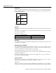
Troubleshooting When the system works abnormally, the Fault LED will illuminate and the audible alarm will beep continuously. In this situation, the panel LEDs will indicate which part inside the UPS is out of order.
Troubleshooting Fault UPS Mode Before Fault Condition UPS Mode After Fault Fault, 3 & 4 Any mode Parallel communication CAN bus loss No output Fault, 2 & 4 Any mode DSP with H8 communications error Bypass or no output 12 Output failure Fault, 1 & 5 Line, Battery Output actual power
Troubleshooting Chloride Linear Plus Series Rack-mount UPS User Instruction Manual 28