
Instruction manual
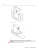
Installation
12 Linear Plus Series User Instruction Manual
Cable Sizes and
Current
The following table indicates the recommended sizes of conductors in accordance with the NEC
®
. (Air
temperature surrounding the conduits not greater than 86°F (30°C).)
NOTE:
Cable sizes are suggested and based on standard configurations. Installers should verify correct
conductor sizes pursuant to NEC
®
and/or state or local codes. If the installation requires long conductor
runs, consult NEC
®
and/or state or local codes to account for electrical losses.
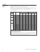
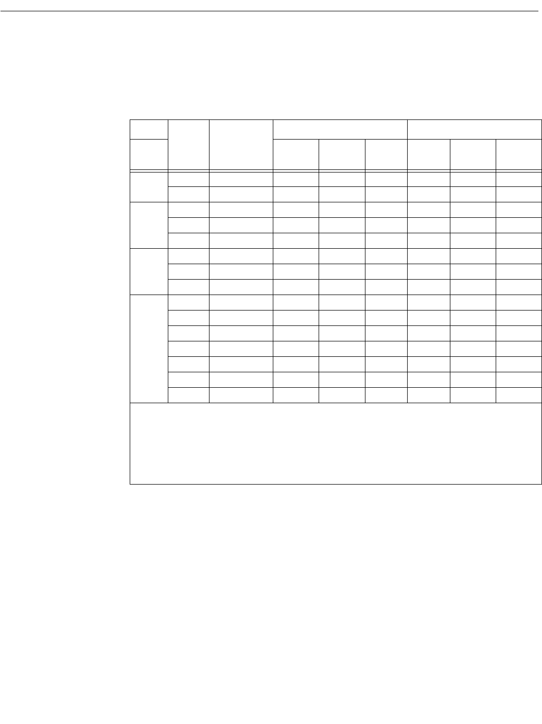
Table 4. Cable Sizes
Term ID Description
6 kVA (4 kVA) 10 kVA (8 kVA)
main wire
gauge (awg
term torque
(in-lbs)
min wire
temp (°C)
*
main wire
gauge (awg
term torque
(in-lbs)
min wire
temp (°C)*
JMP
JL1 Line 1 (Jumper)
‡
8 40 75 6 45 75
JL2 Line 2 (Jumper)
‡
8 40 75 6 45 75
MAIN
ML1 Line 1 (Main) 8 40 75 6 45 75
ML2 Line 2 (Main) 8 40 75 6 45 75
E/G Chassis Ground ** 40 75 ** 45 75
BYPASS
BL1 Line 1 (Bypass) 8 40 75 6 45 75
BL2 Line 2 (Bypass) 8 40 75 6 45 75
E/G Chassis Ground ** 40 75 ** 45 75
OUTPUT
‡‡
X1 Output Term 1 10 35 75 6 45 75
X2 Output Term 2 10 35 75 6 45 75
X3 Output Term 3 10 35 75 6 45 75
E/G Chassis Ground 10 35 75 6 45 75
X4 Output Term 4 10 35 75 6 45 75
X5 Output Term 5 10 35 75 6 45 75
X6 Output Term 6 10 35 75 6 45 75
‡ Wire between JL1 & BL1 and between JL2 & BL2 if only single input power source is used.
‡‡ Output voltage available at output terminals dependent on specific model. See Table 5 - 7 on page 13 for details.
* Use insulated copper wire rated 75°C minimum
** Must be no smaller than wire connected to L1 and L2
NOTE: For installation per IEC regulations
: If installing units per regulations IEC-287 and DIN VDE 0298, 6 kVA model
should be wired (inputs and outputs) with 6 mm
2
cable torqued to 4.5 nt-m; and 10kVA model (inputs and outputs) should be
wired with 10 mm
2
cable torqued to 5.0 nt-m. (Based on 70°C cable and ambient of 30°C)