
Instruction manual
Interfaces
28 Linear Plus Series User Instruction Manual
Optional Isolated
Contacts Card
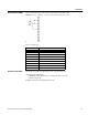
Below are the descriptions of the interface signals for the isolated contacts card that may be installed into
the COM slot. This optional card provides potential-free signaling contacts and a shutdown input.
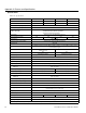
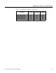
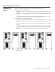
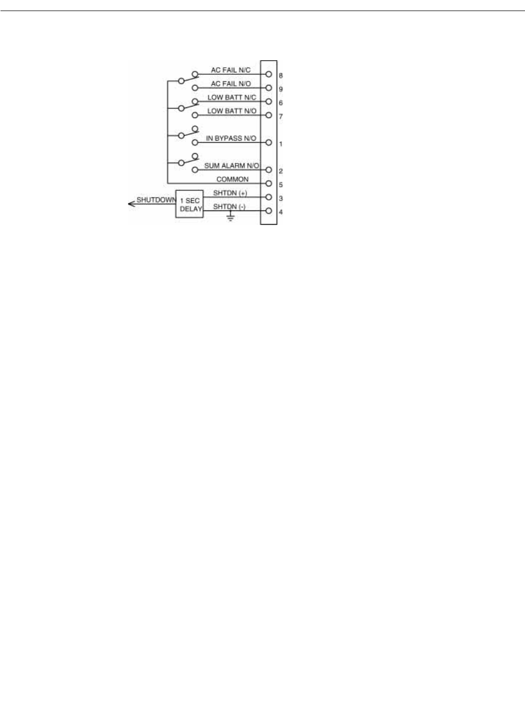
Fig. 17: Isolated Contacts Card Interface Signals
INV SHUTDOWN
This input (pin 3) is enabled with a high signal (+5 V to +12 V with respect to pin 4 (0 V)) and when
enabled, switches off the UPS after a mains failure has occurred. After the mains have been reestablished,
the UPS starts again independent of this signal status. This input must be high for one (1) second before
shut off will occur.
AC FAIL
This output provides an N/O (Normally Open) contact between pins 9 and 5, and an N/C (Normally
Closed) contact between pins 8 and 5. The 9-5 contact closes when the mains voltage fails at the UPS input
or when the mains voltage falls below the lower limit for a minimum of 10 seconds. This contact opens
approximately 850 ms after the mains have been reestablished. The 8-5 contact provides a mirror function,
opening when the mains voltage fails and closing when main power returns
LOW BATT
This output provides a N/O contact between pins 6 and 5 and an N/C contact between pins 7 and 5. The
6-5 contact closes when the battery has been depleted to the point that it can only supply current for
approximately three (3) more minutes at nominal load. The 7-5 contact provides a mirror function opening
when the battery is low.
BYPASS ACTIVE
This output provides an N/O contact between pins 1 and 5. The 1-5 contact closes after switching to the
bypass mode. In the bypass mode, energy to the output of the UPS is being supplied by the mains power
and not through the inverter.
SUM ALARM
This output provides an N/O contact between pins 2 and 5. The 2-5 contact closes when one of the alarms
“AC FAIL,” “LOW BATT” or “BYPASS ACTIVE” is active or when the indication “ALARM” at the
front-panel is on.