Stratus® ftServer® V 2302, V 4304, and V 6308 Systems: Site Planning Guide Stratus Technologies R624-00A
Notice The information contained in this document is subject to change without notice. UNLESS EXPRESSLY SET FORTH IN A WRITTEN AGREEMENT SIGNED BY AN AUTHORIZED REPRESENTATIVE OF STRATUS TECHNOLOGIES, STRATUS MAKES NO WARRANTY OR REPRESENTATION OF ANY KIND WITH RESPECT TO THE INFORMATION CONTAINED HEREIN, INCLUDING WARRANTY OF MERCHANTABILITY AND FITNESS FOR A PURPOSE.
Contents Preface 1. Site Planning for ftServer V 2302, V 4304, and V 6308 Systems Site Planning Overview Site Planning for Fault-Tolerant Systems Site Planning Checklist Preparing to Install a System Preparing to Take Delivery of a System Moving the System to the Installation Site System Documentation Safety Notices 2.
Contents 4. Communications Line Planning RSN Connection Planning Fibre Channel Connections Fibre Channel Connections to ftScalable Storage RAID Controller Trays Fibre Channel Connections to Tape Drive Enclosures Network Connections Maintenance Network Connections Ethernet Cables Ethernet Subnet Requirements Network I/O Enclosure PICMG 2.
Figures Figure 3-1. Figure 3-2. Figure 3-3. Figure 3-4. Figure 4-1. Figure 4-2. Figure 4-3. Figure 4-4. Figure 5-1. Figure 5-2. Figure 5-3. Figure A-1. Figure A-2. Figure A-3. Figure B-1. Figure B-2. Figure B-3. Figure B-4. Figure B-5. Figure B-6. Figure B-7.
Tables Table 1-1. Table 1-2. Table 2-1. Table 2-2. Table 2-3. Table 2-4. Table 2-5. Table 2-6. Table 2-7. Table 4-1. Table 4-5. Table 4-2. Table 4-3. Table 4-4. Table A-1. Table A-2. Table A-3. Table B-1. Table C-1.
Preface The Stratus ftServer V 2302, V 4304, and V 6308 Systems: Site Planning Guide (R624) documents the site requirements and customer responsibilities related to preparing a site for the installation of ftServer V 2302, V 4304, and V 6308 systems. This document is intended for those responsible for preparing a site for the installation of an ftServer V 2302, V 4304, or V 6308 system. Revision Information This document is a revision. It includes: • New marketing IDs for “Network I/O Enclosure PICMG 2.
Preface NOTE A note provides important information about the operation of an ftServer system.
Preface Getting Help If you have a technical question about ftServer system hardware or software, try these online resources first: • Online documentation at the StrataDOC Web site. Stratus provides complimentary access to StrataDOC, an online-documentation service that enables you to view, search, download, and print customer documentation. You can access StrataDOC at the following Web site: http://stratadoc.stratus.com A copy of StrataDOC on supported media for your system is included with this release.
Preface • By email to Comments@stratus.com. If it is possible, please include specific information about the documentation on which you are commenting: – For a printed document or a document in PDF format, include the title and part number from the Notice page and the page numbers. – For online documentation, include the Help subject and topic title. If you are connected to an OpenVOS system, you can comment on this document by using the command comment_on_manual.
Chapter 1 Site Planning for ftServer V 2302, V 4304, and V 6308 Systems 1- For an overview of required information and tasks you need to perform to prepare a site for ftServer V 2302, V 4304, and V 6308 systems, see: • “Site Planning Overview” on page 1-1 • “Site Planning for Fault-Tolerant Systems” on page 1-3 • “Site Planning Checklist” on page 1-3 • “Preparing to Install a System” on page 1-5 • “System Documentation” on page 1-7 • “Safety Notices” on page 1-7 Site Planning Overview Site planning for fa
Site Planning Overview • Space planning Provide adequate space for the system or cabinet and for a desk or table to accommodate components outside a cabinet. Also provide enough space for servicing the systems and components. Provide an environment that meets the system's requirements for ambient temperature and air quality.
Site Planning for Fault-Tolerant Systems Site Planning for Fault-Tolerant Systems Consider the following specific fault-tolerant features of ftServer systems for site planning: • Lockstep technology means that the systems contain redundant hardware. The systems contain two enclosures, each containing a full computing environment that consists of a CPU element and an I/O element.
Site Planning Checklist Planning for Network Connectivity ❏ The system contains four embedded 10/100/1000 megabits-per-second (Mbps) Ethernet ports. Will your system additionally include any of the following PCI adapters for network communications? If so, in Table 1-1, indicate the total number of ports, and plan network connections for all Ethernet ports you will use. Table 1-1.
Preparing to Install a System NOTE Make sure that all cords and cables are long enough to reach between their respective components and connectors. Route all cables out of the way of foot traffic.
Preparing to Install a System NOTE Depending on the system configuration and the components you have ordered, a separate carton containing components may be shipped with your system. When your system arrives, do the following: • Contact the CAC or your authorized Stratus service representative. • Check the Tip-N-Tell and Shockwatch motion sensors to determine if they have been activated.
System Documentation System Documentation Table 1-2 lists the hardware documents for ftServer V 2302, V 4304, and V 6308 systems, and the tasks described in each document. Table 1-2.
Safety Notices ! WARNING The system uses two power cords to provide redundant sources of power. To fully remove power from a system, disconnect both power cords. To reduce the risk that electrical shock could injure a person or damage the system, exercise caution when working in the unit even when only one power cord is connected. ! WARNING To prevent a cabinet from tipping over and injuring a person or damaging the system, start installing systems from the bottom of the cabinet upward.
Safety Notices ! WARNING Disconnect the power cords from the server or power source before you install or relocate the equipment. All voltage is removed only when the power cords are disconnected. ! WARNING Do not install or store the equipment in an unsuitable place. Install or store the equipment in a place that meets the requirements specified in this guide. Avoid the following conditions to avoid the risk of fire.
Safety Notices contact your CAC or your authorized Stratus service representative. ! WARNING Do not connect an interface cable while the server is connected to a power source. Make sure to power off the server and remove the power cord from the server or a power outlet before you install or remove any internal device, or connect or disconnect any interface cables to or from the server.
Safety Notices ! WARNING ! WARNING ! WARNING ! WARNING Site Planning for ftServer V 2302, V 4304, and V 6308 Systems 1-11
Safety Notices 1-12 ! WARNING ! WARNING ! WARNING ! CAUTION Stratus ftServer V 2302, V 4304, and V 6308 Systems: Site Planning Guide (R624)
Chapter 2 AC Power Planning 2- This chapter describes the AC power requirements of ftServer V 2302, V 4304, and V 6308 systems.
AC Power and HVAC Worksheets The top PDU in the cabinet receives power from the A-side power source and distributes power to the following components: • The A-side CPU-I/O enclosure • The A-side of the optional network I/O enclosure • One side of each disk storage enclosure that is installed in the system cabinet • The DVD enclosure • The A-sides of the supported Ethernet and Fibre Channel switches The bottom PDU in the cabinet receives power from the B-side power source and distributes power to the follo
AC Power and HVAC Worksheets For each row in Table 2-1: • Fill in the Quantity of Product Purchased column. • Multiply it by the supplied value in the No. of AC Outlets Required column. • Write the result in the Subtotal of AC Outlets column. • Determine the total number of AC outlets by adding the values in the Subtotal of AC Outlets column. Table 2-1. Worksheet for Planning Site AC Outlets and Cord Lengths Product Purchased ftServer V 2302, V 4304, or V 6308 Quantity of Product — No.
Selecting a UPS Unit for ftServer Systems Table 2-2. Work Sheet for Site AC Power and HVAC Requirements Product Purchased Quantity Watts Watts Subtotal Convert to BTUs ftServer V 2302 systems x 2275† = x 3.41 = ftServer V 4304 and V 6308 systems x 4025‡ = x 3.41 = RSN console server x 4.2 = x 3.41 = RSN modem x 22 = x 3.41 = Optional network I/O enclosure (fully loaded) x 750 = x 3.41 = Legacy D910 FC disk enclosures (fully populated) x 363 = x 3.
Selecting a UPS Unit for ftServer Systems Table 2-3.
Selecting a UPS Unit for ftServer Systems Table 2-3.
Selecting a UPS Unit for ftServer Systems Table 2-4. Qualified APC UPS Models (Page 2 of 2) Region or Country International Japan ftServer System Configuration UPS Quantity, Model Number, and Options Power Output of One UPS (Watts) ftServer V 2302 system Two SYH4K6RMI 2800 ftServer V 2302 system with network I/O enclosure Two SYH4K6RMI (each with one SYBT2 battery) 2800 ftServer V 4304 system Two SYA8K16RMI (each with one SYBT5 battery). Order two B52700-45V cords.
Selecting a UPS Unit for ftServer Systems AC Power Connections to Qualified UPS Models AC input power cords must be hardwired to the qualified UPS models. Table 2-5 lists how the PDU AC input power cords connect to the qualified UPS models. ! WARNING A qualified electrician must supply and hardwire the UPS AC input cord, and if required an AC output cord, distribution panel, or conduit to each UPS unit in compliance with local and national electrical code. Table 2-5.
Power Cord Summary Power Cord Summary Table 2-6 describes where you can find more information about PDU, UPS, and Legacy E124 expansion storage-system cabinet power cords. ! WARNING Place all power cords out of the way of foot traffic. Table 2-6. Power Cords Component Power Cord UPS (model qualified by Stratus) 220 VAC input - Customer supplied (hardwired to UPS AC input terminals) PDU See “AAP87600V PDU Specifications” on page A-6.
Main Cabinet Ground Cables Main Cabinet Ground Cables Table 2-7 provides information about the main cabinet ground cable. Table 2-7. Main Cabinet Ground Cable Component Cable Description Stratus PN Length Cabinet ground leakage cable 10AWG ground leakage cable with 1/4 in. (6.35 mm) and M8 ring lugs AW002000 15 ft (4.6m) ! WARNING Incorrect grounding can cause severe personal injury and extensive equipment damage.
Chapter 3 Space Planning 3- For information about planning sufficient space for your ftServer system, see: • “Room Requirements” on page 3-1 • “Planning for Cables” on page 3-3 Room Requirements To ensure that the installation site provides a properly equipped, cooled, and sized environment, make sure that the site: • Is a computer room • Provides clearances for air circulation, opening cabinet doors, removing cabinet panels, and servicing the system from the front and rear.
Room Requirements Dust contamination on tape devices causes mis-reads and -writes, leading to failure of attempts to back up and restore data. • Has sufficient floor space for external components, such as the optional external E124 storage-system cabinets • Provides a table or desktop for external devices such as a telephone, RSN modem and console server, and a system console. Each of these devices requires table or rack space. You cannot place a peripheral component on top of a system cabinet.
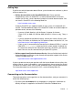
Planning for Cables Figure 3-1 illustrates the space-planning considerations. Figure 3-1. Space-Planning Considerations Ceiling clearance 20 in. (50.8 cm) Service area Future expansion Service area RSN modem RSN console server System console Service area Service area vos120a Cabinet Mounting and Leveling Considerations The main cabinet has cabinet-leveling feet. Anti-tip brackets are optional.
Planning for Cables To accommodate cables from your system, make sure to provide: • One or two telephone lines: – One telephone line for use when calling for service – One telephone line for the RSN modem • Ethernet jacks, switches, or hubs, as needed • Two UPS units, within reach of the power cords from the PDUs • For external components, AC wall outlets within reach of the power cords from the components Make sure that cables you plan to connect to the system are long enough to reach between the system
Creating a Floor Plan Figure 3-2. Cabling Considerations Cable ladder Future Future expansion Expansion Overhead cable tray Phone line RSN modem System console Ethernet Serial RSN console server vos123a Creating a Floor Plan This section provides equipment templates and a site-layout grid to help you plan the placement of the components within the room. Appendix A, “System Specifications” provides detailed specifications for each of the system’s components.
Creating a Floor Plan NOTE Make sure that all cords and cables are long enough to reach between their respective components and connectors. Route all cables out of the way of foot traffic. Figure 3-3 contains the equipment templates to be used in the site-layout grid. The site-layout grid in Figure 3-4 represents a room measuring 20 ft. by 25 ft. (6 m by 8m). Note that the minimum room size for the core system components is 8 ft. by 8 ft. (2.6m by 2.6m). The scale of Figure 3-4 is 1/4-inch (0.
Creating a Floor Plan Figure 3-3. System Equipment Templates ftServer system main cabinet and storage-system cabinets Door space Door space Door space Door space Door space Door space Door space Door space RSN modem Table 3 ft. (.92m) x 4 ft. (1.22m) Table 3 ft. (.92m) x 3 ft. (.92m) RSN console server System console 0 0 1 2 .5 Chair Chair 3 ft. 1m NOTE The shading on the templates indicates the access area required for servicing.
Creating a Floor Plan Figure 3-4.
Chapter 4 Communications Line Planning 4- Make sure that you plan the locations of your ftServer system and its external components so that all communications and data cables will reach their connection points.
Fibre Channel Connections The modem connects to the RSN console server.
Fibre Channel Connections The Stratus ftServer Systems: Peripherals Site Planning Guide (R582) lists the supported optical Fibre Channel HBA. Table 4-1 lists the available optical Fibre Channel cables. Table 4-1. Optical Fibre Channel Cables Length Part number 6.5 ft (2m) AW-B90000-020 32.8 ft (10m) AW-B90000-100 98.4 ft (30m) AW-B90000-300 For detailed instructions for making the Fibre Channel connections, see the ftScalable Storage: Getting Started Guide (R601).
Network Connections For ftServer V 4304 and V 6308 systems, ftScalable Storage RAID controller trays connect to two U773 12-Port Fibre Channel Switches, which in turn connect to the supported HBAs. Figure 4-2 illustrates these connections. Figure 4-2.
Network Connections Maintenance Network Connections Many of the components in ftServer V 2302, V 4304, and V 6308 systems are connected to two U772 24-Port 10/100 Ethernet Switches to form a maintenance network. These components include: • ftScalable Storage RAID controller modules • RSN console server • UPS units • PC console The CAC or other authorized Stratus service representative uses this maintenance network for remote service and debug operations.
Network Connections Figure 4-3 shows the maintenance network Ethernet and RS-232 connections for ftServer V 2302 systems. Figure 4-3.
Network Connections Figure 4-3 shows the maintenance network Ethernet and RS-232 connections for ftServer V 4304 and V 6308 systems. Figure 4-4.
Network Connections Ethernet Cables In addition to the Ethernet cables listed in this section, you must also provide the following Ethernet network support structures: • Network connection points, for the network Ethernet cables from the available Ethernet ports in the CPU- I ⁄ O enclosures. • Separate class C Ethernet subnets for various system components. See “Ethernet Subnet Requirements” on page 4-9 for details. You will need Stratus part number AK-000551 (7 ft.
Network Connections Ethernet Subnet Requirements Table 4-5 lists the minimum separate Class C Ethernet subnet requirements for systems with and without the optional network I/O enclosure. Table 4-5. Ethernet Subnet Requirements System Configuration Separate Class C Ethernet Subnets ftServer system with an optional network I/O enclosure One subnet in the form 10.10.1.X to connect the host system to the maintenance network’s U772 Ethernet switches.
Serial (Null Modem) Cables Table 4-2. Network I/O Enclosure Communications Cable PICMG 2.16 Adapter Cable Description Marketing ID Length U760 Eight-Port Serial Synchronous PICM G 2.16 Adapter Two RS-232C Hydra Cables for breaking out each four-channel connector on the rear transition module to four separate cables B001141V 12.0 ft. (3.65m) Two RS-449 Hydra Cables for breaking out each four-channel connector on the rear transition module to four separate cables B001143V 12.0 ft. (3.
Telephone Line Connections Table 4-3. Null Modem Cables (Page 2 of 2) Marketing ID Length Component Cable Description RSN console server to the RSN modem One DB-25 female to DB-25 female null modem cable, which is provided with the console server, for connecting port 2 of the RSN console server to serial port 1 on the RSN modem. B10102-10V 10 ft. (3.
Cables for External Components cable connects the PC console to a U772 24-Port 10/100 Ethernet Switch to provide web management capabilities of ftScalable Storage systems. See “Ethernet Cables” on page 4-8 for details. Cables for External Components Table 4-4 describes component location considerations due to standard cable lengths. Table 4-4.
Chapter 5 Supported Configurations 5- This chapter contains information about supported cabinet configurations. Cabinet Configurations Figures 5-1 through 5-3 show the supported ftServer system cabinet configurations. The illustrations show the locations of components and filler panels.
Cabinet Configurations Figure 5-1 illustrates an ftServer V 4304 or V 6308 system without the optional ftScalable Storage expansion trays, tape-drive enclosure, and network I/O enclosure. Figure 5-1.
Cabinet Configurations Figure 5-2 illustrates a fully configured ftServer V 4304 or V 6308 system that includes the optional ftScalable Storage expansion trays, tape-drive enclosure, and network I/O enclosure. Figure 5-2.
Cabinet Configurations Figure 5-3 illustrates an ftServer V 2302 system without the optional network I/O enclosure. It is housed in a 24U cabinet. When ordered with the network I/O enclosure, it is housed in a 38U cabinet. Figure 5-3.
Appendix A System Specifications A- For system specifications, see: • “System Specifications” on page A-1 • “AAP87600V PDU Specifications” on page A-6 NOTES 1. The system temperature and humidity requirements defined in Tables A-2 and A-3 are the minimum requirements the site must provide. 2. The temperature and humidity requirements for optional components are provided in the Stratus ftServer Systems: Peripherals Site Planning Guide (R582).
System Specifications Figure A-1. CPU-I⁄O Enclosures: Front View asys009 Figure A-2.
System Specifications Table A-1. Cabinet Dimensions 24U Shipping Container Height (including pallet) 56 in. (1.42m) Width 41 in. (1.04m) Depth 53 in. (1.35m) 38U Shipping Container Height (including pallet) 79.75 in. (2.03m) Width 41 in. (1.04m) Depth 53 in. (1.35m) 24U Cabinet Height (including casters) 50 in. (1.27m) Width 27.5 in. (70 cm) Depth 41 in. (1.04m) Weight, empty 275 lb (125 kg) Weight, empty with pallet and shipping container 436 lb (197.
System Specifications Table A-2. V 2302, V 4304, and V 6308 System CPU-I⁄O Enclosure: Specifications (Page 1 of 2) Power Input power ftServer 2302 and 4304: 500W for each enclosure (1000W total) ftServer 6308: 750W for each enclosure (1500W total) Nominal input voltage 200-240VAC; 50/60 Hz Protective earth ground current 3.5 mA maximum for each AC power cord Physical Dimensions Height 7.0 in. (17.78 cm; 4U) Width 17.50 in. (44.45 cm) Depth 30 in. (76.
System Specifications Table A-2. V 2302, V 4304, and V 6308 System CPU-I⁄O Enclosure: Specifications (Page 2 of 2) Features Processors ftServer 2302: One Dual-Core Intel® Xeon® 2.0 GHz processors in each CPU- I ⁄ O enclosure ftServer 4304: One Quad-Core Intel® Xeon® 2.0 GHz processors in each CPU- I ⁄ O enclosure ftServer 6308: Two Quad-Core Intel® Xeon® 3.
AAP87600V PDU Specifications AAP87600V PDU Specifications The AAP87600V PDU, shown in Figure A-3, supplies power to ftServer systems and optional rack-mountable components. Figure A-3.
AAP87600V PDU Specifications Table A-3 lists the specifications for the AAP87600V PDUs. Table A-3. AAP87600V PDU: Specifications Power Input power N/A Nominal input voltage; frequency 200–240 VAC; 50/60 Hz Physical Dimensions Height 1.75 in. (4.45 cm) Width 19.1 in. (48.51 cm) Depth 6.75 in. (17.15 cm) Environmental Operating temperature during operation Maximum rate of temperature change during operation Relative humidity during operation Storage temperature to 40,000 ft (12.
AAP87600V PDU Specifications A-8 Stratus ftServer V 2302, V 4304, and V 6308 Systems: Site Planning Guide (R624)
Appendix B Electrical Circuit and Wiring Information B- For electrical circuit and wiring information that you need to provide to the contractor and/or facilities personnel responsible for wiring the power at the system installation site, see: • “Fault Protection Requirements” on page B-1 • “Grounding Considerations” on page B-1 • “Circuit Wiring Diagrams” on page B-2 • “Electrical Power Connectors” on page B-8 Fault Protection Requirements Each enclosure in ftServer systems contains internal fault/overl
Circuit Wiring Diagrams As shown in Figure B-1, a star ground is often used to obtain the same earth reference ground. Each earth reference ground, such as the system base ground, is returned separately to a common point where a zero-volt (0V) earth ground exists. The star ground ensures that all equipment is at the same potential and that no noise or safety problems associated with an unpredictable or uncharacterized grounding system will occur. Figure B-1.
Circuit Wiring Diagrams (Line) hot input, and the Y input is connected to the N (Neutral) input. However, for split-phase or three-phase applications, the X and Y inputs are connected to L1, L2, or L3 (separate lines). Therefore, for split-phase or three-phase applications, both X and Y can be electrically hot with respect to the system base (earth reference ground). Figure B-2 shows the physical locations of the X and Y inputs on the system base. Figure B-2.
Circuit Wiring Diagrams Figure B-4 shows a single-phase 240V AC circuit connection. Note that this application requires a single-pole circuit breaker. Figure B-4.
Circuit Wiring Diagrams Figure B-5 shows a split-phase 120/240V AC circuit connection. Note that this application requires a double-pole circuit breaker. Figure B-5.
Circuit Wiring Diagrams Figure B-6 shows a three-phase 208V AC, Y-, or Δ-source circuit connection, which is a phase-to-phase source connection. Note that the X and Y inputs on the system can be connected from L1 and L2, L2 and L3, or L1 and L3. This application requires a double-pole circuit breaker. Figure B-6.
Circuit Wiring Diagrams Figure B-7 shows a three-phase 380V AC, Y-, or Δ-source circuit connection, which is a phase-to-neutral source connection. Note that the system’s X input can be connected to L1, L2, or L3. This application requires a single-pole circuit breaker. Figure B-7.
Electrical Power Connectors Electrical Power Connectors Table B-1 describes the connectors required by the AC power cords that Stratus supplies with ftServer systems. Table B-1.
Appendix C Standards Compliance C- For compliance information, see the following: • “Electronic Interference, Immunity, Safety, and Noise Level Standards Compliance” on page C-1 • “Toxic and Hazardous Substances and Elements Disclosure” on page C-3 Electronic Interference, Immunity, Safety, and Noise Level Standards Compliance All ftServer systems comply with the electromagnetic interference (EMI), immunity, safety, and noise regulations listed in Table C-1.
Electronic Interference, Immunity, Safety, and Noise Level Standards Compliance manual, may cause harmful interference to radio communications. Operation of this equipment in a residential area is likely to cause harmful interference, in which case the user will be required to correct the interference at his own expense. Table C-1.
Toxic and Hazardous Substances and Elements Disclosure Table C-1. Compliance Standards for ftServer V 2302, V 4303, and V 6308 Systems (Continued) Standard Title Country VCCI V-3 2006.04 Class A Voluntary Control Council for Interference by Information Technology Equipment Japan SABS IEC 60950 Safety of Information Technology Equipment South Africa RRL 2008-39 (2008.5.19), 2008-3 (2008-5-21), 2008-38 (2008.5.19), 2008-4 (2008-4 (2008.5.
Toxic and Hazardous Substances and Elements Disclosure C-4 Stratus ftServer V 2302, V 4304, and V 6308 Systems: Site Planning Guide (R624)
Index A AC power, 2-1 cords, 2-9 specifications, 2-9 UPS, 2-8 requirements, 2-3 source, 2-1 worksheet, 2-2 American Power Conversion (APC). See APC anti-tip brackets, 3-3 APC UPS, 2-6 APC UPS qualified models, 2-6 A-side power source, 2-1 B B-side power source, 2-1 C cabinets specifications, A-3 cables Fibre Channel, 4-3 ground, 2-10 network I/O enclosure, 4-9 PICMG 2.
Index H R hubs, network, 3-4 HVAC worksheet, 2-2 removing power, 1-8 room requirements, 3-1 RSN connection cables, 4-1 site planning, 3-4 I IEC 60309 connector, B-8 installation site floor plan, 3-5 layout sample grid, 3-6 templates, 3-6 moving system to, 1-6 preparation, 1-5 ISO 14644-1 class 8 standards, 3-1 J jacks, Ethernet, 3-4 L leveling feet, 3-3 M main cabinet anti-tip brackets, 3-3 leveling feet, 3-3 N NEMA L6-20 connector, B-8 network I/O enclosure cables, 4-9 P PC console, 1-2 requireme
Index three-phase circuit connections 208 V AC, B-6 380 V AC, B-7 U U772 Ethernet switch, 4-9, 4-12 uninterruptible power supply (UPS).
Index Index-4 Stratus ftServer V 2302, V 4304, and V 6308 Systems: Site Planning Guide (R624)