
Product Info


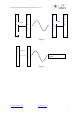


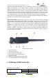
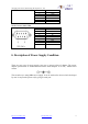
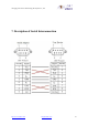
Table Of Contents
- 1. Brief Introduction
- 2. Technical Specifications
- 4. Description of indicator and press-button
- 5. Definition of DB9 Socket Pin
- 6. Description of Power Supply Condition
- 7. Description of Serial Interconnection
- 8. Instructions
- 9. Configuration Tools
- 10. AT command
- 1. Test command
- 2. Set / Inquire the baud rate
- 3. Set / Inquire the serial communication mode
- 4. Set / Inquire authentication password
- 5. Set/Inquire Name
- 6. Set / Inquire Sniff power-saving mode
- 7. Set / Inquire the parameters of inquiring scan and connecting scan
- 8. Set / Inquire whether authenticate
- 9. Set / Inquire device type
- 10. Set / Inquire device role
- 11. Set / Inquire the data processing mode when not connected
- 12. Set / Inquire flow control mode
- 13. Set / Inquire the type of data device
- 14. Set / Inquire whether it is bind
- 15. Set/Inquire the memorized remoted Bluetooth device
- 16. Clear the memorized address
- 17. Inquire local Bluetooth address
- 18. Inquire software version
- 19. Software reset
- 20. Inquire remoted Bluetooth devices
- 21. Cancel inquire remoted Bluetooth devices
- 22. Restore default settings
- 23. Inquire all commands
- 11. FAQ:
- 1 After powering the module, the indicator of the Module doesn’t blink.
- 2 When there are multiple Bluetooth devices around, how to connect to the specified Bluetooth device?
- 3 How to operate if want to connect with multiply devices at the same time?
- 4 How the multipoint connections send and receive data? And what are the differences between the sending & receiving of multipoint and point-to -point connections?
- 5 Can not set the parameters, or use the Configuration Tools displaying "connection timeout" when connects to the PC
- 6 How to send AT command by your hand?
- 7 Two serial adapter can not connect with each other
- 8 Why PC, USB Dongle cannot find the serial adapter?
- 9 Why PC USB Dongle and serial adapter cannot realize data communication or only communicate by one-way data communication?
- 10 How to communicate with PDA?
- 11 How to communicate with Bluetooth mobile phone?
- 12.1 Equipment Type Number
- 12.2 MAJOR SERVICE CLASSES
- 12.3 MAJOR DEVICE CLASSES
- 12.4 THE MINOR DEVICE CLASS FIELD
- 12.5 MINOR DEVICE CLASS FIELD - COMPUTER MAJOR CLASS
- 12.6 MINOR DEVICE CLASS FIELD - PHONE MAJOR CLASS
- 12.7 MINOR DEVICE CLASS FIELD - LAN/NETWORK ACCESS POINT MAJOR CLASS
- 12.8 MINOR DEVICE CLASS FIELD - AUDIO/VIDEO MAJOR CLASS
- 12.9 MINOR DEVICE CLASS FIELD - PERIPHERAL MAJOR CLASS
- 12.10 MINOR DEVICE CLASS FIELD - IMAGING MAJOR CLASS

Chongqing Jinou Science &Technology Development Co., Ltd.
http://www.oemblue.com/ info@oemblue.com
8
connection with other Bluetooth devices. If blinking, it means not establish connection.
When not connecting, we can judge whether it memorize the address (that is whether
matches other Bluetooth device of not) or not through the green light’s blinking speed. If
blinking quickly (twice every second), it means it has remembered the address; if blinking
slowly (once every second), it does not remember. For master device, it blinks once every
3 seconds when query. When matching, it blinks quickly four times every second; when
connecting, blink once every second; after connecting, the indicator light extinguishes.
When RS232 is working under the parameter setting condition, the master/slave indicator
light and connecting state indicator light extinguish.
Mode switch button: In data model state, press Cmd button, the two working condition
indicator light of the 100M Wireless RS232 Serial Adapter extinguish. At this time 100M
Wireless RS232 Serial Adapter works under the parameter setting condition and returns "+
OPEN: 0" from serial port. In parameter setting condition, 100M Wireless RS232 Serial
Adapter stops working, and can only set the parameter 100M Wireless RS232 Serial
Adapter. In parameter settings state, press the Cmd button and RS232 adapter exit
parameter condition, and begin to work.(searching, matching, connecting, sending data
etc.); but cannot set 100M Wireless RS232 Serial Adapter parameters. After powering, it
enters data mode state default.
Figure 4 Outside View
1. RS232 Connector
2. DC Power Connector
3. Power Indicator Light (red)
4. Mode Switch Button (CMD button)
5. External Antenna
6. Master/Slave Mode Indicator Light (red)
7. Connection Mode Indicator Light (green)
5. Definition of DB9 Socket Pin
Hole Pattern (Female) DB9
Pin No
Signal
1
VCC
2
TXD