Introduction The G90S is an amateur radio short-wave transceiver with a portable 20W in the SDR architecture. It is a new member of the Xiegu product family and the first portable SDR model in the G series. Based on 24bit-C0DEC sampling, the G90S brings superior transceiver performance and a highly configurable feature experience; the separate head design allows you to flexibly position your host; with built-in high-performance ATU, you can meet your needs at any time.
Specification & Parameters General parameters Frequency range: Receiving: 0.5MHz~30MHz Transmitting: 1.8~2.0MHz 18.068~18.168MHz 3.5~3.9MHz 21.0~21.45MHz 7.0~7.2MHz 24.89~24.99MHz 10.1~10.15MHz 28.0~29.7MHz 14.0~14.35MHz Operating mode: CW, AM, SSB Minimum step: 10Hz 50Ω Antenna impedance: 0°C ~ +50°C Scope of working temperature: ±1.5ppm in the 10~60min after startup Frequency stability: @25°C: 1ppm/hour 10.5~16.
Specification & Parameters Receiver parameters Circuit type: ZIF Neighbor channel suppression: ≥60dB Sideband suppression: ≥60dB Sensitivity: 0.5~1.79999MHz 1.8~1.99999MHz 2.0~27.9999MHz 28.0~30.0MHz SSB/CW / 0.35uV 0.25uV 0.25uV AM 10uV 10uV 2uV 2uV (PRE=on, ATT=off, NB=off, NR=off, SSB/CW/AM=10dB S/N) Mirroring suppression: 70dB Midband suppression: 60dB Audio output: 0.5W (8Ω, ≤10% THD) Audio output impedance: 4~16Ω ♦ Above specifications may be changed without notice.
Accessories & Optional Components Accessories of host: Multi-function hand microphone : 1 in number USB cable: : 1 in number DB9 extension line: : 1 in number Separating head fixing stud : 2 nos Hexagon wrench : 1 in number Power line : 1 in number Warranty card : 1 in number Instructions : 1 in number Quality certificate : 1 in number *Optional components: CE19: host ACC adapter (can be used as data communication to transmit audio signal or to connect XPA125B amplifier) XPA125B: 100W power amplifier + auto
Interface Definition Definition of microphone interface Wiring diagram of COMM plug Wiring diagram of earphone plug Definition of ACC terminal Signal Signal Tail ACC socket Wire connection of telegram keys Di Di Da Da Common Common Note: ♦ If the connector of the telegraph key is a 6.5mm 2-core plug, please change it to a 3-core 3.5mm stereo plug according to the wiring method shown in the figure above, and connect the trigger end of the electric key to the "Di" or "Da" terminal.
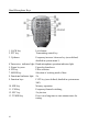
Machine Interface 1 Volume knob • Turn the knob to increase or decrease the volume. • Short press the knob to switch to the headphone output mode. 2 Power supply/transceiver indicator light • Standby/receiving state: yellow-green; • It is red under transmitting state. 3 Power switch • In the power off state, short press this key to turn it on. • In the power on state, long press this key to shut it down. Under startup state, short press the key to turn off the screen display and save electricity.
Panel Keys 12 Function keys The key definitions and functions are detailed in the operation section (Page 12).
Machine Interface 13 Antenna interface SL16-K type interface, impedance 50Ω. 14 KEY interface It is a 3.5mm stereo interface used to connect manual/auto telegram keys. (See Page 5 for the wiring method) 15 COMM interface It is used for updating the machine hardware. 16 I/Q signal output port It is a 3.5mm interface (3 wires) used for IQ signal output. 17 ACC interface The interface is an 8-core mini-type DIN interface. See the interface definition for details.
Machine Interface 20 MIC (microphone) interface (located on the right side) It is used to connect attached multi-function handheld microphone. 21 22 21 Headphone interface (located on the left side) It is a 3.5mm stereo socket (3 wires) interface used to connect earphones. (See Page 5 for the wiring method) 22 Communication interface (located on the left side) It is used for hardware updating of head unit and the on-line control with computer. ■ Notes: 1.
Hand Microphone Keys 1. LOCK key 2. PTT key Lock button Transmitting control key 3. Up/down Frequency increase/ decrease key (user-defined, detailed in system menu 1) 4.Transceiver indicator light Hand microphone operation indicator light 5. Figure key area Figure keyboard area 6. FIL key Filter selection 7. MODE key Selection of working mode of host 8. Functional indicator light No 9. Function keys F1/F2 key (user-defined, detailed in system menu 2&3) 10. MW key Memory operation 11.
Power Source Connection The 13.8V external DC power supply is available for G90S. Current load capacity of DC power supply shall be 8A at least. Attached power lines can be used to connect to radio and DC power supply. DC power supply shall be connected in strict accordance with following figure to avoid reverse polarity connection. ■ Red line shall be connected with the positive pole of power supply and black line shall be connected with negative pole of power supply.
Functions of Panel Keys and Switching Button PRE/ATT First function (short press, cycle) PRE - ATT - direction connection CMP/F-L Turn it on to transmit voice compression NB/F-H NB SW-NB Level-NB Width AGC/SPL Open AGC, F-S+A close and circulating VM. Switch frequency mode or channel mode MW/MC Turn on channel memory function A/B.
Screen Display Icon Status display area Mode display Power supply voltage indication VFO display area Receive bandwidth indication Volume indication Multi-function indicator Receiving state is meter s Transmission state is power meter Standing-wave display area Receiving level display Spectrogram display area Waterfall diagram display area Function and definition of display icon: : pre-amplifier is open. The icon character A refers that the pre-attenuator is open.
Operation Dear user, in order to familiarize you with the functions and proficiency of the G90S portable transceiver as soon as possible, please read the operation guide of this manual to understand the powerful functions of the G90S. Let's start! ----------------------------------------------------------------------------------------------- Transceiver start and shutdown 1. Start the transceiver: short press key . 2. Shut down the transceiver: press and hold key state.
Operation Selection of Working Frequency Range: Frequency band decrease Frequency band increase Frequency range of G90S covers 0.5~30MHz. Amateur frequency in such range is divided into 10 frequency bands, and frequency band switch can be achieved by adopting many types of different modes. Operation methods: Continuously pressure [<] or [>] keys of BAND to switch the operating frequency bands cyclically: ■ Each amateur band has a user-defined frequency band that is convenient for temporary use.
Operation Volume adjustment Speaker mode: Turn the volume knob to the left or right to adjust the output volume. Headphone mode: 1. Short press the volume knob to enter the headphone mode. 2. Volume knob Turn the volume knob to the left or right to adjust the headphone volume. ♦ Please turn the volume to the minimum before using earphone for the purpose of protecting your ears. Gradually adjust the volume to be appropriate as required after the earphone is inserted.
Operation Working Frequency Setting There are two methods for setting working frequency of G90S, i.e., set by using the large knob or multi-function hand microphone. 1. Set frequency by using main knob Press the main knob in a short time to select the 100Hz, 1kHz, 10kHz and 100KHz stepping positions; Main knob Rotate main knob and set the frequency of current step. 2.
Operation Adjustment of RF Gain and Muting Level RF GIAN / SQL Proper RF gain can facilitate to improve the quality of signal received. In general, Appropriately reducing the RF gain value at some low-frequency ranges with strong interference can significantly improve the hearing. Adjustment methods of RF gain: 1. Long press [AGC] key at the bottom of the screen to call the setting option RFGAIN. 2. Rotate the main knob to adjust the RF gain value. 3.
Operation Press in a short time: Enter the receiving filter mode to select. Long press: Enter the user defined function menu, rotate the main knob to select the corresponding function, and press the SAVE key at the bottom of the screen in a short time to select the function. At this point, the function is set to the [Multi-function adjustment knob].
Operation ♦ VFOA/B can be fully used to set different frequencies and modes,so as to quickly switch the two frequency points in real time. ----------------------------------------------------------------------------------------------- Automatic Gain Control (AGC) Select appropriate AGC control parameters in different work modes to achieve a good receiving effect. 1.
Operation PRE AMP/ATT The pre-amplifier can improve the receiving effect of some weak signals of high frequency range and the sensitivity of the receiver. 1. Press [PRE] key at the bottom of the screen in a short time and the character P will appear on the top left corner of the screen, indicating that the pre-amplifier is turned on. 2. Press [PRE] key again in a short time and the character A will appear on the top left corner of the screen, indicating that the pre-attenuator is turned on. 3.
Operation ■ NB suppression width and level can be properly adjusted to effectively suppress different kinds of pulse interference. ■ improper NB parameter setting will severely affect the receiving effect. Disabling the NB function at ordinary times is recommended. ----------------------------------------------------------------------------------------------- Voice Compression CMP The voice compression can increase the average power output during the voice communication so that signals can be resonant.
Operation CW Communication Use telegraph keys or external keying unit to insert into the KEY port at the tail of the radio. (See Page 5 for the definition of wiring) 1. Insert keys into the KEY port; 2. Press [MODE] key to switch to CW (or CWR) mode; 3. Enable the QSK function in the [KEY] key function and set the appropriate QSK time; 4. Press telegram key to enable CW communication.
Operation SSB Communication Insert the hand microphone into the MIC port on the right side of the radio head unit. After inserting, the green indicator light on the hand microphone shall be on. 1. Press [MODE] key () at the top of the head, and switch to LSB or USB mode. setting, indicating that the band width is 2.4kHz. 2. Enter the second function of [POW] key for the following settings: 3.
Operation Automatic Antenna Tuner There is an efficient ATU integrated inside the G90S radio to help you quickly erect and debug antenna. 1. Press [TUNE] key in a short time to connect with built-in antenna tuner. There will be an antenna icon at the top of screen. 2. In the case that the antenna tuner is accessed, long press and hold the [TUNE] key for 1s to start ATU automatic tuning functions. IT will automatically return to receiving state after the tuning. Note: 1.
Operation Fine Tuning of Received Frequency (RIT) Operation methods: 1. Long press the main knob to enter the RIT adjustment interface. 2. Rotate the main knob left or right to adjust the RIT value. The adjustment range is ±500Hz and relevant information displays on the screen. ♦ After RIT function is used, reset the RIT value to be 0 to avoid affecting the normal use.
Operation Channel Memory MW and Clear MC Basic operations: 1. In VFO mode, adjust the required frequency, mode, advanced function status and other parameters. 2. Press [MW/MC] key in a short time and the CH 00 (channel number) character will appear on the screen and flash. Rotate the main knob to select an empty channel. At this time, the character E will appear after the channel number, indicating that the channel is empty and can be used for memory. 3.
Operation Digital Filter The G90S has a built-in variable digital filter that can continuously adjust the bandwidth of the filter and improve the anti-interference performance and selectivity of the radio. The G90S has two filter adjustment modes: center frequency point mode and bandwidth mode. 1. Press [Multi-function adjustment knob] in a short time to respectively switch these two filter modes. 2.
Operation Spectrum/ Waterfall Display The G90S radio can display the spectrum diagram and waterfall diagram of receiving signals and can quickly observe whether there is communication signal on the neighboring frequency so that uses can quickly track and switch frequencies and search the radio.
Operation Data Communication The G90S supports all amateur data communication modes and the full-function control of the computer software to the radio. Only simple wiring is needed for the amateur data communication. Appropriate digital work mode shall be selected before operation.
Operation The audio head wiring diagram is on CE-19 panel The joint definition in this diagram indicates the output signal terminal of the radio.
Operation Connection between the G90S and XPA125B (optional) After the G90S connects with XPA125 power amplifier and antenna tuner AIO through the CE19 adapter, the output power can be expanded to 100W. ACC interface 8-core wire 6-core wire Schematic Diagram of Wiring between G90S and XPA125B After connection, the G90S can automatically control the wave band switching of XPA125B. Moreover, the ALC control will be built between two machines.
Description of System Menu System Menu The system menu enables customized setup for partial functions. You may use this feature to configure the settings suitable for you. Operation method: Hold the [FUNC] key to enter the system menu.
Description of System Menu Menu item 1: Handle up/down Function: Customize the function of [▲▼] key on multi-purpose hand microphone. Optional value: FREQCH+/BAND+/VOLUM+/- Frequency/channel+/Band+/Volume+/- Default: FREQCH+/Menu item 2: Handle F1 Function: Customize the function of [F1] key on multi-purpose hand microphone. Optional value: PRE/ATT SPLT NB COMP AGC Default: PRE/ATT Menu item 3: Handle F2 Function: Customize the function of [F2] key on multi-purpose hand microphone.
Description of System Menu Menu item 6: AUX OUT Volum Function: Set the volume of ACC port output audio signal Adjustable range: 0~15 The large the value, the greater the volume Default: 15 Menu item 7: RCLK Tune Function: Regulate the reference clock of radio's internal frequency combiner. Able to correct the frequency deviation of the radio. Adjustable range: -1000Hz~+1000Hz Default: 0Hz Eg.
Factory Reset Factory Reset When the parameters of the radio is disarranged or in case of any other situation that causes improper parameters, this function enables the restoration of factory settings. Operation methods: 1. Hold the FNUC key to start up and enter the restoration of factory settings. 2. Press PRE key to confirm the implementation. Press VM key to cancel the operation and exit. ■ Default parameters can meet most operating needs, ensuring the radio is working under good conditions.
CIV control instructions Computer Control Instructions G90S adopts standard CIV instruction sets. You can remotely control the transceiver based on standard instructions of the instruction set or configure control instructions of other softwares, so as to achieve the control on G90S. See specific specifications of CI-V instructions in CI-V COMMUNICATIONS INTERFACE-V REFERENCE MANUAL.
Copyright Statement All Rights Reserved, 2019 Chongqing Xiegu Technology Co., Ltd. reserves all rights of the manual. All parts of the manual shall not be copied without permission.
This device complies with part 15 of the FCC Rules. Operation is subject to the following two conditions: (1) this device may not cause harmful interference, and (2) this device must accept any interference received, including interference that may cause undesired operation. Any changes or modifications not expressly approved by the party responsible for compliance could void the user's authority to operate the equipment.