Chord Electronics Product Communication | English The Pumphouse, Farleigh Lane, East Farleigh, Kent, ME16 9NB. Great Britain. +44 (0) 1622 721 444 info@chordelectronics.co.uk chordelectronics.co.uk ULTIMA 6 Manual - V.1.
Chord Electronics ULTIMA 6 | Manual _ Contents 0.0 1.0 Safety instructions 03 2.0 Warranty 08 1.1 1.2 1.3 1.4 04 05 06 2.1 2.2 09 Introduction Protection against liquids & heat Dismantling & Radio frequency interference Connecting your equipment 3.0 Getting to know ULTIMA 6 3.1 3.2 3.3 3.4 Getting to know ULTIMA 6 The front panel The top panel The rear panel 0.0 2 // 24 Warranty period & registering your purchase Making a claim & warranty exclusions 10 07 11 12 13 14 15 4.
Chord Electronics ULTIMA 6 | Manual _ Safety instructions 1.0 3 // 24 1.0 1.1 Introduction 1.2 Protection against liquids & heat 1.3 Dismantling & Radio Frequency interference 1.
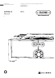
1.1 1.2 Chord Electronics ULTIMA 6 | Manual _ Introduction ULTIMA 6 is an incredibly reliable and technologically advanced stereo power amplifier. It represents the entry into Chord Electronics Full Size amplification ownership with a dual-feedforward error-correction topology. Before operation, we strongly advise that you read this user manual thoroughly, storing it in a safe place along with your original receipt of purchase, in case you should require assistance in the future. 4 // 24 1.
1.1 1.2 Chord Electronics ULTIMA 6 | Manual _ Protection against liquids & heat The ULTIMA 6 is not protected against liquids of any kind. Never place containers of liquid on ULTIMA 6. Never allow ULTIMA 6 to come into contact with moisture or liquids; doing so could result in electrocution or damage to the ULTIMA 6 internal circuitry.
1.1 1.2 Chord Electronics ULTIMA 6 | Manual _ Dismantling & radio frequency interference There are no userserviceable components within the ULTIMA 6 or its power supply. Dangerous voltages/currents exist within the ULTIMA 6 and its power supply, posing a severe risk of electrocution and/or fire. 6 // 24 1.3 1.4 Dismantling & radio frequency interference Connecting your equipment 1.
1.1 1.2 Chord Electronics ULTIMA 6 | Manual _ Connecting your equipment Before connecting the ULTIMA 6 to any equipment, consult the manufacturer’s user guide to confirm compatibility. When connecting the ULTIMA 6 to any equipment, make sure that all devices are off, including the ULTIMA 6. Once connected, switch all equipment on starting with the source and ending with the amplification.
Chord Electronics ULTIMA 6 | Manual _ Warranty 2.0 8 // 24 2.0 2.1 Warranty period & registering your purchase 2.
2.1 Chord Electronics ULTIMA 6 | Manual _ Warranty period & registering your purchase At point of sale, Chord Electronics Ltd. provides ULTIMA 6 with a comprehensive five-year warranty* which covers defects in materials and workmanship through fair wear and tear. The warranty will be void if any other PSU other than that supplied is used. *The warranty is transferable with proof of purchase, however, warranty on ex-demonstration units begins from the retailer‘s date of purchase.
2.1 Chord Electronics ULTIMA 6 | Manual _ Making a claim & warranty exclusions In the unlikely event of a claim, you must provide Chord Electronics with the details of the claim, including your original proof of purchase and serial number in order to validate the nature of the repair. Upon receipt, Chord Electronics will make an assessment within 30 days and provide a reasonable solution.
Chord Electronics ULTIMA 6 | Manual _ Getting to know ULTIMA 6 3.0 11 // 24 3.0 3.1 Getting to know ULTIMA 6 3.2 The front panel 3.3 The top panel 3.
3.1 3.2 Chord Electronics ULTIMA 6 | Manual _ Getting to know ULTIMA 6 Before operation, we strongly advise you read this user manual thoroughly, storing it in a safe place along with your original receipt of purchase, should you require assistance in the future. 12 // 24 3.1 Getting to know ULTIMA 6 The front panel 3.3 3.
3.1 3.2 Chord Electronics ULTIMA 6 | Manual _ The front panel Getting to know ULTIMA 6 The front panel 3.3 3.4 3.2 With only two buttons, everyday operation of ULTIMA 6 is simple and you can tailor the brightness of the feature lighting to suit the ambience of your listening room. Please view page 23 to learn how to do this. WARNING: You must keep all vents clear.
3.1 3.2 Chord Electronics ULTIMA 6 | Manual _ The top panel Getting to know ULTIMA 6 The front panel The top panel The rear panel 3.3 The top panel has no user configurable options. Instead, three teal feature light rings illuminate. If you find that these rings are too bright for your listening room you can control the brightness via the front panel. WARNING: You must keep all vents clear. Stackable Integra legs Light ring 14 // 24 3.3 3.
3.1 3.2 Chord Electronics ULTIMA 6 | Manual _ The rear panel Getting to know ULTIMA 6 The front panel 3.3 3.4 The top panel The rear panel 3.4 The rear panel offers a comprehensive connectivity suite, featuring both standard connections and those which are used with other Chord Electronics’ devices. WARNING: You must keep all vents clear. When installing any cable, you must make sure that they securly click into place, especially optical.
Chord Electronics ULTIMA 6 | Manual _ Setting up ULTIMA 6 4.0 16 // 24 4.0 4.1 Placement 4.2 Connecting ULTIMA 6 to ancillary equipment 4.3 Audio inputs 4.4 Audio outputs 4.5 Power-on sequence and 12V trigger 4.
4.1 4.2 Chord Electronics ULTIMA 6 | Manual _ Placement Whilst ULTIMA 6 will operate normally within a typical Chord Electronics configuration, stacked via the Integra legs, it is recommended that ULTIMA 6 is allowed to ‘breathe’ with 10cm of space around it to convectioncool during operation. 17 // 24 4.3 4.4 4.1 Placement Connecting ULTIMA 6 to ancillary equipment Audio inputs Audio outputs 4.5 4.6 4.
4.1 4.2 Chord Electronics ULTIMA 6 | Manual _ Connecting ULTIMA 6 to ancillary equipment When connecting the ULTIMA 6 to equipment within the signal path, ensure all devices are switched off. It is recommended that once all equipment is properly connected, that the volume setting is operated to its lowest setting, before slowly being raised to a comfortable listening level. Always observe partnering manufacturers’ guidelines. 18 // 24 4.3 4.4 4.
4.1 4.2 Chord Electronics ULTIMA 6 | Manual _ 4.3 4.4 Audio inputs Placement Connecting ULTIMA 6 to ancillary equipment Audio inputs Audio outputs 4.5 4.6 4.7 4.3 WARNING: ULTIMA 6 must be connected to a dedicated preamplifier, or a device capable of attenuating its output. Failure to attenuate the volume before it enters ULTIMA 6 could result in irreversible hearing damage, speaker damage and could void the warranty.
4.1 4.2 Chord Electronics ULTIMA 6 | Manual _ 4.3 4.4 Audio outputs Placement Connecting ULTIMA 6 to ancillary equipment Audio inputs Audio outputs 4.6 4.7 Power-on sequence and 12V trigger Earthing issues in Europe Adjusting the brightness of the LED‘s 4.4 As ULTIMA 6 is a stereo amplifier, it supports 2 speaker outputs. In order to connect ULTIMA 6 to loudspeakers, use high-quality loudspeaker cable terminated with 4mm banana plugs or 6mm spades.
4.1 4.2 Chord Electronics ULTIMA 6 | Manual _ Power-on sequence and 12V trigger POWER-ON SEQUENCE: During normal operation, when ULTIMA 6 is in standby mode the large power button on the front panel will illuminate an red colour. To power-on ULTIMA 6 press the large power button once until you feel a click. ULTIMA 6’s power button will now change to a green colour whilst it begins its initial safety checks.
4.1 4.2 Chord Electronics ULTIMA 6 | Manual _ Earthing issues in Europe In some European countries, a hum or buzz may occur if the amplifier is connected to mains sockets that do not have an earth or adequate earth. If this occurs, please ensure that your equipment is connected via a good-quality multi-way mains block which contains an earth point at every socket outlet. We recommend that an earthing method for your building is implemented. 22 // 24 4.3 4.4 4.
4.1 4.2 Chord Electronics ULTIMA 6 | Manual _ Adjusting the brightness of the LED‘s At any time, you can adjust the brightness of the LEDs to suit your listening environment. Simply locate the hidden button in the middle of the faceplate as indicated below, insert a thin object and push until you hear an audible ‘click’. The light ring and power button will cycle between low and high brightness modes. 23 // 24 4.3 4.4 4.