
Specifications


Operating Manual Freeze Dryer ALPHA 1-4 LD-2 / 2-4 LD-2, Version 0203, Page 15
2.7 Initial start-up
CAUTION! Ensure that the freeze dryer is correctly mounted and installed before
initial start-up (see point 2.1 Site and following points).
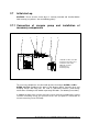
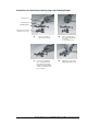
2.7.1
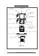
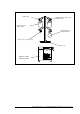
Connection of vacuum pump and installation of
accessory components
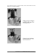
The accessory components are connected up to the freeze dryer ALPHA 1-4 LD-2 /
ALPHA 2-4 LD-2 according to the process flow diagram above. Centering rings and
clamping flanges with wing nuts are used as connecting elements (small flange
connections according to ISO 28403 respectively DIN 2861, see following instructions)
In addition the plug of the vacuum measuring sensor must be inserted into the socket
“Vacuum measuring sensor” on the back of the unit (see point 3.4 connection of
vacuum measuring sensor TPR 265).
1 ALPHA 1-4 LD-2 / 2-4 LD-2
2 Vacuum measuring sensor
3 Vacuum release valve
4 Manual stop valve
5 Vacuum hose
6 Vacuum pump
6
4
3
3
5
2
1