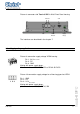
Operating Instructions Touch-Panel Touch-it XPC Document No. Revision Date E461201 01 22.09.2010 Address Christ-Elektronik GmbH Alpenstraße 34 DE-87700 Memmingen +49 (0)8331 8371 – 0 +49 (0)8331 8371 – 99 info@christ-elektronik.de http://www.christ-elektronik.de Telephone Fax E-Mail Internet Copyright No part of this documentation may in any form whatsoever be reproduced, nor used, copied or distributed by means of electronic systems without previous written permission by Christ-Elektronik GmbH.
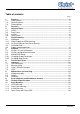
Table of contents Page 1. 1.1. 1.2. 1.3. 2. 3. 3.1. 3.2. 3.3. 3.4. 4. 4.1. 4.1.1. 4.1.2. 4.2. 4.3. 5. 5.1. 5.2. 5.3. 5.3.1. 5.3.2. 6. 7. 7.1. 7.2. 7.3. 7.4. 8. 8.1. 8.2. 8.3. 9. 10. 11. 11.1. 11.2. 11.3. 11.4. 1 Pointers..................................................................................................................2 Used symbols..........................................................................................................2 General pointers.....................................
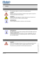
1. Pointers 1.1. Used symbols Symbols The following symbols are used in this instruction manual: DANGER! Denotes a direct threat of danger. Not observing this pointer may be life threatening or lead to serious injuries. CAUTION! Denotes a possibly dangerous situation. Not observing this pointer can cause minor injuries or lead to material damages. INFORMATION! Denotes application pointers and other useful information. 1.2.
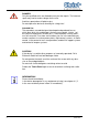
DANGER! Only the qualified staffs are allowed to carry out the repairs. The incorrect repair may lead to serious danger for the user. Avoid any penetration of liquid or dust. Do not expose the device to humidity for a long time! Intended Use These products are not designed, developed and produced for use, which pose fatal risks and dangers that may cause death, injuries, serious physical impairments or other loss, if no exceptional security measures are ensured.
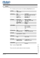
2. General This instruction manual concerns the following Touch-Panel version: 1. Series Type Touch-it XPC 2. Housing Type Vesa Front Panel In Wall Open Frame Installation desk stand, surface mounting fastening clamp in the wall for dashboard 3. Display Screen size 10,4“ (26,4 cm) 15,0” (38,1 cm) Technology TFT Native resolution 800 x 600, 1024 x 768 1024 x 768 Colours 262.000 1 2 3 CCFL switched CCFL controlled LED Type Intel Atom N270 Frequency 1,6 GHz, FSB 533 MHz 4. Backlight 5.
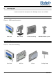
3. Housing Types In order to mount the touch panel, the following variants are available: 3.1. VESA Picture 1: VESA mounting variants front view 3.2.
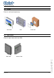
3.3. In Wall Picture 3: wall mounting housing front view 3.4.
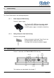
4. Commissioning 4.1. Equipment The Touch-Panel contains the following equipment: 4.1.1. Power Supply for VESA Housing Picture 5: power supply The Touch-it XPC VESA housing needs a power supply with Hirose connector (see chapter 4.3). A 24VDC power supply is included in the delivery. 4.1.2. Fasting Clamp for Front Panel Housing Picture 6: fasting clamp Before you begin installing the Touch-Panel, into front panel please make sure that the 10 clamps with setscrews have been shipped. 4.2.
Picture 8: connector side Touch-it XPC In Wall/ Front Panel housing Ethernet USB VGA COM1 EIA-232 Supply voltage The interfaces are described in the chapter 7. 4.3.
5. Software 5.1. System Test and Initialization These routines test and initialize board hardware. If the routines encounter an error during the tests, you will either hear a few short beeps or see an error message on the screen. There are two kinds of errors: fatal and non-fatal. The system can usually continue the boot up sequence with non-fatal errors.
Integrated Peripherals Use this menu to specify your settings for integrated peripherals. (Primary slave, secondary slave, keyboard, mouse etc.) Power Management Setup Use this menu to specify your settings for power management. (HDD power down, power on by ring, KB wake up, etc.) 5.3.1. Changing Display Resolution Once in the Setup mode choose the [Advanced Chipset Features] Menu and set the Internal LVDS as follows: 10.4” Display 15.
6. Touch Panel Driver 1. Click on [Start] [All Programs] [Pen Mount Universal Driver] [Pen Mount Control Panel] 2.
3. Click on [Standard Calibration] E461201 12 Touch-it XPC 4. Pressing the [Standard Calibration] button on the main window activates the calibration screen to carry out calibration of the Touch Panel. Briefly touch the centre of the red square splayed on the screen in order as they appear. Once calibration is carried out, the calibrated value is saved. Since the calibrated value is read from the setting file at the time of the next start up, there is no need to carry out calibration again.
7. Interfaces The following interfaces are available: • USB2.0 • Ethernet • COM • VGA (LAN, 2x) (EIA-232) Picture 11: connector side Touch-it XPC Ethernet VGA COM1 EIA-232 USB Switch ON/OFF Supply voltage Connection of the supply voltage, see chapter 4.3. 7.1. USB connection The Touch-it XPC offers two USB ports. The USB connections are provided for the connection of storage media as well as peripheral equipment (USB Mouse or Keyboard).
7.2. Ethernet (LAN) The connection to an Ethernet network (10/100/1000BASE-TX) is carried out with a RJ45 socket. It is recommended to use a CAT. 5 cable or higher for the connection to the network. Picture 13: pin assignment Ethernet (RJ45 socket) pin 1: D1+ pin 2: D1pin 3: D2+ pin 4: D3+ pin 5: D3pin 6: D2pin 7: D4+ pin 8: D4- The Touch-it XPC offers two Ethernet network interfaces. 7.3.
8. Maintenance and servicing 8.1. Maintenance plan INFORMATION! Only the manufacturer (Christ-Elektronik GmbH) is allowed to replace the internal lithium battery. The calibration of the touch may be required from time to time. 8.2. Repairs DANGER! Only the qualified staffs are allowed to carry out the repairs. The incorrect repair may lead to serious danger for the user. 8.3. Cleaning DANGER! Disconnect the Touch-Panel from the supply voltage before cleaning.
9. Error treatment and Disturbance removal Error Touch-Panel does not function Application download not possible anymore Cause Wrong voltage supply Voltage failure during a download. This could damage the bootloader.
10. Technical Specifications Touch-it XPC 104 150 10,4“ (26,4 cm) 215 x 162 800 x 600, 1024 x 768 15” (38,1 cm) 304 x 228 1024 x 768 Display Screen Size Display Dimensions [mm] Native Resolution (Pixel) Technology Colours Backlight Luminance [cd/m²] TFT 262.
Touch-it XPC 104 150 Material Front Chassis (wall, front panel) Chassis VESA Weight [kg] anodised aluminium galvanised metal anodised aluminium 2,5 4,6 User Environment E461201 0 to +50 °C -10 to +70 °C 5% to 80% (non condensing) IP 65 IP 20 CE, EN55022, EN55024, EN60950-1, DIN EN ISO 9001 This is a Class A product. In a domestic environment this product may cause radio interference, in which case the user may be required to take adequate measures.
11. Scale Drawing 11.1.
E461201 20 Touch-it XPC Picture 17: dimensions Touch-it XPC 15”
11.2.
E461201 22 Touch-it XPC Picture 19: dimensions Touch-it XPC 10,4” fanless
Picture 20: dimensions Touch-it XPC 15” with fan 23 E461201
E461201 24 Touch-it XPC Picture 21: dimensions Touch-it XPC 15” fanless
11.3.
E461201 26 Touch-it XPC Picture 23: dimensions front frame for Touch-it XPC 10,4”
Picture 24: dimensions In Wall Box for Touch-it XPC 10,4” 27 E461201
E461201 28 Touch-it XPC Picture 25: dimensions Touch-it XPC 15”
Picture 26: dimensions front frame for Touch-it XPC 15” 29 E461201
E461201 30 Touch-it XPC Picture 27: dimensions In Wall Box for Touch-it XPC 15”
11.4.