03-012100-01 ✽ Projection lens is optional.
Features and Design This Multimedia Projector is designed with most advanced technology for portability, durability, and ease of use. This projector utilizes built-in multimedia features, a palette of 1.07 billion colors, and matrix liquid crystal display (LCD) technology. ◆ Functionally Rich This projector has many useful functions such as lens shifting, ceiling and rear projection, perpendicular omnidirectional projection, variety of lens options, etc.
Table of Contents Features and Design . . . . . . . . . . . . . . . . Table of Contents . . . . . . . . . . . . . . . . . . . To The Owner . . . . . . . . . . . . . . . . . . . . . . Safety Instructions . . . . . . . . . . . . . . . . . 2 3 4 5 Air Circulation 6 Installing the Projector in Proper Directions 7 Moving the Projector 8 Cautions in Handling the Projector 8 Compliance . . . . . . . . . . . . . . . . .
To The Owner Before installing and operating the projector, read this manual thoroughly. The projector provides many convenient features and functions. Operating the projector properly enables you to manage those features and maintains it in good condition for many years to come. Improper operation may result in not only shortening the product life, but also malfunctions, fire hazard, or other accidents.
Safety Instructions All the safety and operating instructions should be read before the product is operated. Read all of the instructions given here and retain them for later use. Unplug this projector from AC power supply before cleaning. Do not use liquid or aerosol cleaners. Use a damp cloth for cleaning. This projector should be operated only from the type of power source indicated on the marking label.
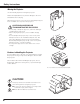
Safety Instructions Air Circulation Openings in the cabinet are provided for ventilation. To ensure reliable operation of the product and to protect it from overheating, these openings must not be blocked or covered. CAUTION Hot air is exhausted from the exhaust vent. When using or installing the projector, the following precautions should be taken. – Do not put any flammable object or spray can near the projector, hot air is exhausted from the air vents.
Safety Instructions Installing the Projector in Proper Directions Use the projector properly in specified positions. Improper positioning may reduce the lamp life and result in severe accident or fire hazard. This projector can project the picture in upward, downward, or inclined position in perpendicular direction to the horizontal plane. When installing the projector in downwardly inclined position, install the projector bottom side up.
Safety Instructions Moving the Projector Use the handle grip when moving the projector. Retract the adjustable feet to prevent damage to the lens and cabinet when carrying. When this projector is not in use for an extended period, put it into a suitable case to protect the projector. CAUTION IN CARRYING OR TRANSPORTING THE PROJECTOR – Do not drop or bump the projector, otherwise damages or malfunctions may result. – When carrying the projector, use a suitable carrying case.
Compliance Federal Communications Commission Notice Note: This equipment has been tested and found to comply with the limits for a Class B digital device, pursuant to Part 15 of the FCC Rules. These limits are designed to provide reasonable protection against harmful interference in a residential installation. This equipment generates, uses and can radiate radio frequency energy and, if not installed and used in accordance with the instructions, may cause harmful interference to radio communications.
Part Names and Functions Front w q q w e r t y u i o !0 !1 e Indicators Top Cover Top Cover Release Button Infrared Remote Receiver (Front) Projection Lens (optional) Light-Block Sheet Adjustable Feet Air Intake Vent Filter Cover Lamp Cover Exhaust Vent CAUTION Hot air is exhausted from the exhaust vent. Do not put heat-sensitive objects near this side.
Part Names and Functions Rear Terminal !0 q ] w o e [ r i t u y q COMPUTER INPUT TERMINAL (DIGITAL) Connect the computer output digital signal to this terminal. The HDTV (HDCP compatible) signal can also be connected (pp.20-21). u CONTROL PORT CONNECTOR w COMPUTER INPUT TERMINAL (ANALOG) Connect the computer (or RGB scart) output signal to this terminal (pp.20-21).
Part Names and Functions Side Control and Indicators Side Control Indicators (on the top panel) q u w e i r o !0 !1 t y q ON/STAND-BY button Turn the projector on or off (pp.23–24). w INPUT button Select an input source (pp.31–33). e LENS button Enter the focus, zoom, and lens shift adjustment mode (p.27). r Point ed7 8 buttons – Select an item or adjust the value in the OnScreen Menu (p.25). – Pan the image in Digital zoom + mode (p.40).
Part Names and Functions Remote Control e w q r t !2 y !1 u !0 i o q STAND-BY button Turn the projector off (p.24). w Wired Remote jack Connect the remote control cable (not supplied) to this jack when using as a wired remote control. e Signal Emission indicator Light red while a signal is being sent from the remote control to the projector. r ON button Turn the projector on (p.23). t INPUT 1 – 3 buttons Select an input source (INPUT 1 – INPUT 3) (pp.31–33).
Part Names and Functions Remote Control @6 !3 @5 !4 @7 @4 For PIN code and remote control code. !5 @3 !6 @2 @1 !7 !8 @0 !9 !3 MENU button Open or close the On-Screen Menu (p.25). @2 KEYSTONE button !4 P-TIMER button Operate the P-timer function (p.29). @3 LENS SHIFT button Select the Lens Shift function (p.28). !5 D.ZOOM button Select the Digital zoom +/- mode and resize the image (p.40). @4 SCREEN button !6 ZOOM ed buttons Zoom in and out the images (p.28). !7 INFO.
Part Names and Functions Remote Control Battery Installation 1 Open the battery compartment lid. 2 Install new batteries into the compartment. Press the lid downward and slide it. 3 Replace the compartment lid. Two AAA size batteries For correct polarity (+ and –), be sure battery terminals are in contact with pins in the compartment. To insure safe operation, please observe the following precautions : ● Use two (2) AAA or LR03 type alkaline batteries. ● Always replace batteries in sets.
Part Names and Functions Remote Control Code The eight different remote control codes (Code 1–Code 8) are assigned to this projector. Switching the remote control codes prevents interference from other remote controls when several projectors or video equipment next to each other are operated at the same time. Change the remote control code for the projector first before changing that for the remote control. See “Remote control” in the Setting Menu on page 51.
Installation Adjustable Feet Projection angle can be adjusted up to 6.5 degrees with the adjustable feet. Rotate the adjustable feet and tilt the projector to the proper height; to raise the projector, rotate the both feet clockwise. To lower the projector or to retract the adjustable feet, rotate the both feet counterclockwise. To correct keystone distortion, press the KEYSTONE button on the remote control or select Keystone from the menu (see pages 14, 29, 40, 44).
Installation Lens Installation When replacing the lens or using an optional lens, install the lens by following the instructions below. Ask the sales dealer for detailed information of the optional lens specifications. Removing the lens 1 Shift the lens to the center position by using the Lens shift function (p. 27). 2 While pressing the top cover release button on the top cover, slide the top cover toward front to remove it 3 4 Slide the light-block sheet upward and remove it.
Installation Attaching the lens to the projector 1 Fit the lens to the projector. Make sure that the lens is fully inserted to the projector. 2 Push the Lens Lock Lever downward. Make sure that the lens is properly locked. 3 Slide the light-block sheet in the groove to mount. 4 While pressing the top cover release button on the top cover, slide the top cover back to the projector. Groove NOTES ON LENS INSTALLATION ● Do not touch or remove any parts except the lens and related parts.
Installation Connecting to a Computer (Digital and Analog RGB) Cables used for connection • VGA Cable (One cable is supplied.) • DVI-Digital Cable ✽ • BNC Cable ✽ USB port USB cable USB Monitor Output BNC cable (✽ = Cables not supplied with this projector.) • Serial Cross Cable✽ • USB Cable Monitor Output DVI-Digital cable G B R H/V V Unplug the power cords of both the projector and external equipment from the AC outlet before connecting cables.
Installation Connecting to Video Equipment (Video, S-Video) Cables used for connection (✽ = Cables not supplied with this projector.) • Video Cable (RCA x 1 or RCA x 3) ✽ • BNC Cable ✽ • S-VIDEO Cable ✽ • Scart-VGA Cable ✽ Monitor Out Signal Table Input 1 Input 2 Unplug the power cords of both the projector and external equipment from the AC outlet before connecting cables.
Installation Connecting the AC Power Cord This projector uses nominal input voltages of 100–120 V or 200– 240 V AC and it automatically selects the correct input voltage. It is designed to work with single-phase power systems having a grounded neutral conductor. To reduce the risk of electrical shock, do not plug into any other type of power system. If you are not sure of the type of power being supplied, consult your authorized dealer or service station.
Basic Operation Turning On the Projector 1 Complete peripheral connections (with a computer, VCR, etc.) before turning on the projector. 2 Connect the projector’s AC power cord into an AC outlet. The LAMP indicator lights red and the POWER indicator lights green. 3 Press the ON/STAND-BY button on the side control or the ON button on the remote control. The LAMP indicator dims and the cooling fans start to operate. The preparation display appears on the screen and the countdown starts.
Basic Operation Turning Off the Projector 1 Press the ON/STAND-BY button on the side control or the STAND-BY button on the remote control, and “Power off?” appears on the screen. 2 Press the ON/STAND-BY button on the side control or the STAND-BY button on the remote control again to turn off the projector. The LAMP indicator lights bright and the POWER indicator turns off. After the projector is turned off, the cooling fans operate for 90 seconds.
Basic Operation How to Operate the On-Screen Menu The projector can be adjusted or set via the On-Screen Menu. For each adjustment and setting procedure, refer to the respective sections in this manual. Side Control 1 Press the MENU button on the side control or the remote control to display the On-Screen Menu. POINT buttons 2 Use the Point 7 8 buttons to select a Menu icon. Use the Point ed buttons to select an item in the selected menu.
Basic Operation Menu Bar For detailed functions of each menu, see “Menu Tree” on pages 66-68. For Computer Source Image Select Menu Guide Window PC System Menu Show the selected Menu of the OnScreen Menu. Used to select computer system (p. 34). Used to select an image level among Standard, Real, and Image 1–10 (p. 38). Information Menu Screen Menu Used to adjust the size of the image. [Normal/True/ Wide/Full screen/Custom/ Keystone/Ceiling/Rear/Reset/ Digital zoom +/–] (pp.39-40).
Basic Operation Operating with Projector Control Lens Operation The following lens operation can be made with the Lens button on the side control. Side Control LENS button Press the LENS button to enter each lens operation mode. The selected adjustment display appears on the screen. Zoom ➜ Focus ➜ Lens Shift ➜ POINT buttons ••••• Zoom Adjustment Display “Zoom” on the screen. Use the Point ed buttons to zoom in and out the image. ZOOM Focus Adjustment Display “Focus” on the screen.
Basic Operation Operating with Remote Control Using the remote control for some frequently used operations is advisable. Just pressing one of the buttons enables you to make the desired operation quickly without calling up the On-Screen Menu. FREEZE button Press the FREEZE button on the remote control to freeze the picture on the screen. To cancel the FREEZE function, press the FREEZE button again or press any other button.
Basic Operation Remote Control FILTER button Press and hold the FILTER button for more than five seconds to operate electrically operated filter to replace the filter. NO SHOW button Press the NO SHOW button on the remote control to black out the image. To restore to normal, press the NO SHOW button again or press any other button. MOUSE POINTER button P-TIMER button “No show” disappears after 4 seconds.
Basic Operation Pointer Function You can move the Pointer of the projector with the remote control to emphasize a part of the projected image. 1 Press the POINTER button to activate the Pointer function. MOUSE POINTER button 2 Use the MOUSE POINTER button to move the Pointer. 3 To cancel the Pointer function, press the POINTER button again or press any other button. POINTER button Pointer ✔Note: • You can choose the pattern of Pointer (Arrow/Finger/Dot) in the Setting Menu (p.
Input Selection Input Side Control Side Control button operation INPUT button INPUT button Input 1 Input 2 Input 3 Side Control Operation Press the INPUT button on the side control. It switches to INPUT 1, INPUT 2, and INPUT 3 as you press the INPUT button. Before using the INPUT button on the side control, you must select a correct input source by On-Screen Menu and the latest input source will be displayed.
Input Selection Computer Input Source Selection Menu Operation WHEN SELECTING INPUT 1 (COMPUTER INPUT TERMINALS ) 1 Press the MENU button to display the On-Screen Menu. Use the Point 7 8 buttons to move the red frame pointer to the INPUT Menu icon. 2 Use the Point ed buttons to move the red arrow pointer to the desired input and then press the SELECT button. The Source Select Menu appears. 3 INPUT MENU Input Menu icon Move the pointer (red arrow) to Input 1 and press the SELECT button.
Input Selection Video Input Source Selection Menu Operation WHEN SELECTING INPUT 1 (COMPUTER INPUT TERMINALS ) When connecting to video equipment, select the type of Video source in the Source Select Menu. INPUT MENU Input Menu icon RGB (Scart) When scart video equipment is connected to the INPUT 1 (ANALOG) terminal, select RGB (Scart). RGB (AV HDCP) If the HDCP-compatible signal source is connected to the INPUT 1 (DIGITAL) terminal, select RGB (AV HDCP).
Computer Input Computer System Selection Automatic Multi-Scan System This projector automatically tunes to various types of computers based on VGA, SVGA, XGA, SXGA, SXGA+, WXGA, or UXGA (refer to “Compatible Computer Specifications” on pages 71–72). If a computer is selected as a signal source, this projector automatically detects the signal format and tunes to project a proper image without any additional settings. (Some computers need to be set manually.
Computer Input Auto PC Adjustment Auto PC Adjustment function is provided to automatically adjust Fine sync, Total dots, Horizontal and Vertical positions to conform to your computer. Direct Operation Remote Control The Auto PC adjustment function can be operated directly by pressing the AUTO PC button on the remote control. AUTO PC button Menu Operation Auto PC adj. 1 Press the MENU button to display the On-Screen Menu.
Computer Input Manual PC Adjustment Some computers employ special signal formats which may not be tuned by Multi-Scan system of this projector. Manual PC Adjustment enables you to precisely adjust several parameters to match those special signal formats. The projector has 10 independent memory areas to store those parameters manually adjusted. It allows you to recall the setting for a specific computer.
Computer Input Reset To reset the adjusted data, select Reset and press the SELECT button. A confirmation box appears and then select [Yes]. All adjustments will return to their previous figures. Mode free To clear the adjusted data. To clear the adjusted data, select Mode free and then press the SELECT button. Move the red arrow pointer to the Mode that you want to clear and then press the SELECT button. Store To store the adjusted data, select Store and then press the SELECT button.
Computer Input Image Level Selection Menu Operation 1 Press the MENU button to display the On-Screen Menu. Use the Point 7 8 buttons to move the red frame pointer to the Image Select Menu icon. 2 Use the Point ed buttons to move the red frame pointer to the desired image level and then press the SELECT button. Standard Normal picture level preset on the projector. Real Picture level with improved halftone for graphics. IMAGE 1–10 User preset picture adjustment in the Image Adjust Menu. (p.
Computer Input Screen Size Adjustment Select the desired screen size that conforms to the input signal source. 1 Press the MENU button to display the On-Screen Menu. Use the Point 7 8 buttons to move the red frame pointer to the Screen Menu icon. 2 Use the Point ed buttons to move the red frame pointer to the desired function and then press the SELECT button. SCREEN MENU Screen Menu icon Normal Move the red frame pointer to the desired function and press the SELECT button.
Computer Input Keystone This function is used to store or reset the keystone correction when the AC power cord is unplugged. Use the Point 7 8 buttons to switch between each option. Store . . . Keep the keystone correction even when the AC power cord is unplugged. Reset . . . Release the keystone correction when the AC power cord is unplugged. SCREEN MENU Move the red frame pointer to the desired function and press the SELECT button. To correct keystone distortion, press the Select button.
Video Input Video System Selection 1 Press the MENU button to display the On-Screen Menu. Use the Point 7 8 buttons to move the red frame pointer to the AV System Menu icon. 2 Use the Point ed buttons to move the red arrow pointer to the desired system and then press the SELECT button. Video Jack or S-Video Jack Auto The projector automatically detects an incoming video system, and adjusts itself to optimize its performance. When Video System is PAL-M or PAL-N, select the system manually.
Video Input Image Level Selection Menu Operation 1 Press the MENU button to display the On-Screen Menu. Use the Point 7 8 buttons to move the red frame pointer to the Image Select Menu icon. 2 Use the Point ed buttons to move the red frame pointer to the desired image level and then press the SELECT button. Standard Normal picture level preset on the projector. Cinema Picture level adjusted with fine tone. IMAGE 1–10 User preset picture adjustment in the Image Adjust Menu. (p.
Video Input Screen Size Adjustment 1 Press the MENU button to display the On-Screen Menu. Use the Point 7 8 buttons to move the red frame pointer to the Screen Menu icon. 2 Use the Point ed buttons to move the red frame pointer to the desired function and then press the SELECT button. SCREEN MENU Screen Menu icon Move the red frame pointer to the desired function and press the SELECT button. Normal Provide the image at the normal video aspect ratio of 4:3.
Video Input Keystone This function is used to store or reset the keystone correction when the AC power cord is unplugged. Use the Point 7 8 buttons to switch between each option. Store . . . Keep the keystone correction even when the AC power cord is unplugged. Reset . . . Release the keystone correction when the AC power cord is unplugged. SCREEN MENU Move the red frame pointer to a function and press the SELECT button. To correct keystone distortion, press the Select button.
Picture Image Image Adjustment 1 Press the MENU button to display the On-Screen Menu. Use the Point 7 8 buttons to move the red frame pointer to the Image Adjust Menu icon. 2 Use the Point ed buttons to move the red frame pointer to the desired item and then press the SELECT button to display the adjustment dialog box. Use the Point 7 8 buttons to adjust the setting value. IMAGE ADJUST MENU Image Adjust Menu icon Move the red frame pointer to the desired item and then press SELECT button.
Picture Image COLOR SELECTION MODE (continued) COLOR M. Return to the COLOR MANAGEMENT POINTER. (If you press the MENU button on the side control or the remote control, it returns to the COLOR MANAGEMENT POINTER and you will need to reselect and readjust the color.) COLOR SELECTION MODE Level and phase adjustment palette. Gamma adjustment palette. MENU Return to the IMAGE ADJUST Menu. Any settings that have been changed will not be stored.
Picture Image White balance (Red/Green/Blue) Press the Point 7 button to lighten red/green/blue tone; press the Point 8 button to deepen red/green/blue tone (from 0 to 63). Offset (Red/Green/Blue) Press the Point 7 button to lighten red/green/blue tone of the black level of an image; press the Point 8 button to deepen red/green/ blue tone of the black level of an image (from 0 to 63). Sharpness Press the SELECT button at this icon to display other items.
Setting Setting This projector has a Setting menu that allows you to set up other various functions. 1 Press the MENU button to display the On-Screen Menu. Use the Point 7 8 buttons to move the red frame pointer to the Setting Menu icon. 2 Use the Point ed buttons to move the red frame pointer to the desired item and then press the SELECT button. The Setting dialog box appears. SETTING MENU (Language) Setting Menu icon Set the red frame pointer to the item and press the SELECT button.
Setting Logo This function allows you to customize the screen logo with Logo select, Capture, and Logo PIN code lock functions. Logo ✔Note: • When “On” is selected in the Logo PIN code lock function, Logo select and Capture functions cannot be selected. Logo select This function decides on the starting-up display from among the following options. User . . . . Show the image you captured. Default . . Show the factory-set logo. Off . . . . . Show the countdown display only.
Setting Logo PIN code lock This function prevents an unauthorized person from changing the screen logo. Logo PIN Code Lock Off . . . . . The screen logo can be changed freely from the Logo Menu. On . . . . . The screen logo cannot be changed without a Logo PIN code. If you want to change the Logo PIN code lock setting, press the SELECT button and the Logo PIN code dialog box appears. Enter a Logo PIN code by following the steps below. The initial Logo PIN code is set to “4321” at the factory.
Setting Lamp control This function allows you to change the brightness of the screen. Auto . . . . . . Brightness according to the input signal. Normal . . . . Normal brightness. Eco 1 . . . . . Lower brightness and Fan control set to Normal. Lower brightness reduces the lamp power consumption and extends the lamp life. Eco 2 . . . . . Lower brightness and Fan control set to Max. Lower brightness reduces the lamp power consumption and extends the lamp life.
Setting USB The Projector has a USB port for interactive operation between the projector and computers. Set the mode by following the steps below. Wireless Mouse mode Select “ ” when controlling a computer with the remote control of this projector. Projector mode: “ ” Not used. Power management Power management For reducing power consumption as well as maintaining the lamp life, the Power management function turns off the projection lamp when the projector is not used for a certain period.
Setting Security Security Key lock This function locks the side control and remote control buttons to prevent operation by unauthorized persons. . . . . . Unlocked. . . . . . Lock the side control buttons. To unlock, use the remote control. . . . . . Lock the remote control buttons. To unlock, use the side control. If the side control accidentally becomes locked and you do not have the remote control nearby and unable to operate the projector, contact the service station.
Setting Enter a PIN code Use the Point ed buttons on the side control or Number buttons on the remote control to enter a number. When using side control Use the Point ed buttons on the side control to select a number. Press the Point 8 button to fix the number and move the red frame pointer to the next box. The number changes to “✳.” Repeat this step to complete entering a four-digit number. After entering the four-digit number, move the pointer to “Set.
Setting Filter counter Filter counter This function is used to set a frequency for the filter replacement. Use the Point ed buttons to move the red frame pointer to Filter counter and then press the SELECT button. A dialog box appears showing the Used time option and the Scrolls remaining option. Used Time . . . . . . Show the total accumulated time of the filter use, timer setting option and the Reset options. When the projector reaches a time set in the timer setting, the Filter replacement icon (Fig.
Maintenance and Care Filter Instructions Filter prevents dust from accumulating on the optical elements inside the projector. Should the filter becomes clogged with dust particles, it will reduce cooling fans’ effectiveness and may result in internal heat buildup and adversely affect the life of the projector. This projector has an electrically operated filter which helps you to replace the filter easily.
Maintenance and Care Replacing the Filter Cartridge 1 Turn off the projector, and unplug the AC power cord from the AC outlet. 2 First, clean up the dust on the projector and around the air vents. 3 Press s on the filter cover to release the latch and open the filter cover. 4 Pull out the filter cartridge. When taking out the filter cartridge, put your finger on the filter cartridge’s tab and then pull. 5 Put the new one back into the position and close the filter cover.
Maintenance and Care Resetting the Filter Counter Be sure to reset the Filter counter after replacing the filter and the filter cartridge. 1 Press the MENU button to display the On-Screen Menu. Use the Point 7 8 buttons to move the red frame pointer to the Setting Menu icon. 2 Use the Point ed buttons to move the red frame pointer to Filter counter and then press the SELECT button. A dialog box appears showing the Used time option and the Scrolls remaining option.
Maintenance and Care Lamp Replacement When the projection lamp of the projector reaches its end of life, the Lamp replacement icon appears on the screen and LAMP REPLACE indicator lights orange. Replace the lamp with a new one promptly. The timing when the LAMP REPLACE indicator should light is depending on the lamp mode. Filter cover Lamp cover Top Panel Lamp replacement icon Screw LAMP REPLACE indicator ✔Note: • The Lamp replacement icon will not appear when the Display function is set to “Off” (p.
Maintenance and Care Resetting the Lamp Counter Be sure to reset the Lamp counter after the lamp is replaced. When the Lamp counter is reset, the LAMP REPLACE indicator stops lighting and the Lamp replacement icon disappears. 1 Press the MENU button to display the On-Screen Menu. Use the Point 7 8 buttons to move the red frame pointer to the Setting Menu icon 2 Use the Point ed buttons to move the red frame pointer to Lamp counter and then press the SELECT button.
Maintenance and Care LAMP HANDLING PRECAUTIONS This projector uses a high-pressure lamp which must be handled carefully and properly. Improper handling may result in accidents, injury, or create a fire hazard. ● Lamp lifetime may differ from lamp to lamp and according to the environment of use. There is no guarantee of the same lifetime for each lamp. Some lamps may fail or terminate their lifetime in a shorter period of time than other similar lamps.
Maintenance and Care Cleaning the Projection Lens Unplug the AC power cord before cleaning. Gently wipe the projection lens with a cleaning cloth that contains a small amount of non-abrasive camera lens cleaner, or use a lens cleaning paper or commercially available air blower to clean the lens. Avoid using an excessive amount of cleaner. Abrasive cleaners, solvents, or other harsh chemicals might scratch the surface of the lens. Cleaning the Projector Cabinet Unplug the AC power cord before cleaning.
Maintenance and Care Warning Indicators The WARNING indicators show the state of the function which protects the projector. Check the state of the WARNING indicators and the POWER indicator to take proper maintenance. The projector is shut down and the WARNING TEMP. indicator is blinking red. Top Panel When the temperature inside the projector reaches a certain level, the projector will be automatically shut down to protect the inside of the projector.
Appendix Troubleshooting Before calling your dealer or service center for assistance, check the items below once again. 1. Make sure you have properly connected the projector to peripheral equipment as described on pages 20–21. 2. Check the cable connection. Make sure that all computers, video equipment, and power cords are properly connected. 3. Make sure that all power is switched on. 4. If the projector still does not produce an image, restart your computer. 5.
Appendix Problem: Try These Solutions Check the batteries. Check if the ALL-OFF switch on the remote control is set to “ON.” Check if the RC sensor is set properly. (See page 51) Make sure no obstruction is between the projector and the remote control. Make sure you are not too far from the projector when using the remote control. Maximum operating range is 16.4’ (5 m). Make sure that the remote control code conforms to the projector’s code. (See page 51.
Appendix Menu Tree Computer Input/Video Input Input Input 1 Go to System (1) RGB (PC analog) RGB (Scart) RGB (PC digital) Go to System (1) RGB (AV HDCP) Input 2 Input 3 Information Information Video Go to System (2) Y, Pb/Cb,Pr/Cr Go to System (3) RGB Go to System (1) Video Go to System (2) Y, Pb/Cb,Pr/Cr Go to System (3) S-video Go to System (2) Image Adjust Input H-sync freq. V-sync freq.
Appendix Computer Input System (1) Image Select Mode 1 Standard Mode 2 Real SVGA 1 Image 1 SVGA 2 SVGA 3 Image 10 ✽ System displayed in the System Menu varies depending on the input signal. PC Adjust Screen Auto PC adj. Fine sync.
Appendix Computer Input/Video Input Setting 12 languages provided. Language Quit Menu Position/Simple Menu Display On/Countdown Off/Off Background Logo Blue/User/Black Logo select User/Default/Off Capture Yes/No Logo PIN code lock On/Off Logo PIN code change Quit Quit Lamp control Auto/Normal/Eco 1/Eco 2 Filter control Yes/No Fan control Normal/Max Remote Control Code 1 Code 8 Quit Both/Front/Back RC sensor USB Mouse Projector Power management Off Ready Shut down 1–30 Min.
Appendix Indicators and Projector Condition Check the indicators for the projector condition. The projector is operating normally. Indicators POWER green LAMP red Projector Condition WARNING WARNING LAMP TEMP. FILTER REPLACE red orange orange ✽ v The projector is off. (The AC power cord is unplugged.) ✽ v The projector is in stand-by mode. Press the ON/STAND-BY button to turn on the projector. ✽ v The projector is operating normally.
Appendix Indicators POWER green LAMP red Projector Condition WARNING WARNING LAMP TEMP. FILTER REPLACE red orange orange ✽ v The projector has been cooled down enough and the temperature returns to normal. When turning on the projector, the WARNING TEMP. indicator stops blinking. Check and replace the filter. ✽ The lamp cannot light up. (The projector is preparing for standby or the projection lamp is being cooled down. The projector cannot be turned on until cooling is completed.
Appendix Compatible Computer Specifications Basically this projector can accept the signal from all computers with the V- and H-Frequency mentioned below and less than 180 MHz of Dot Clock. PC Adjustment is limited when selecting these modes.
Appendix When an input signal is digital from the DVI terminal, refer to the chart below. ON-SCREEN DISPLAY D-VGA D-480p D-575p D-SVGA D-XGA D-WXGA 1 D-WXGA 2 D-WXGA 3 D-WXGA 4 D-WXGA 5 D-WXGA 6 D-WXGA 7 RESOLUTION 640x480 720x480 720x575 800x600 1024x768 1366x768 1360x768 1376x768 1360x768 1366x768 1280x768 1280x768 H-Freq. (kHz) 31.470 31.470 31.250 37.879 43.363 48.360 47.700 48.360 56.160 46.500 47.776 60.289 V-Freq.(Hz) 59.940 59.880 50.000 60.320 60.000 60.000 60.000 60.000 72.000 50.000 59.870 74.
Appendix Technical Specifications Mechanical Information Projector Type Multi-media Projector Dimensions (W x H x D) 14.56” x 7.36” x 17.32” (370 mm x 187 mm x 440 mm) (Not including raised portions) Net Weight 25.8 lbs (11.7 kg) Feet Adjustment 0˚ to 6.5˚ Panel Resolution LCD Panel System 1.
Appendix Optional Parts The parts listed below are optionally available. When ordering those parts, specify the item name and Model No. to the sales dealer. Model No. Standard Zoom Lens : 38-809050-01 Long Zoom Lens : 38-809048-01 Ultra Long Zoom Lens : 38-809068-01 Short Zoom Lens : 38-809047-01 Short Fixed Lens : 38-809049-01 Lens Replacement The lens of this projector can be replaced with other optional lens.
Appendix Configurations of Terminals ANALOG/ MONITOR OUT (Mini D-sub 15 pin) 5 15 10 4 14 9 3 13 2 8 1 7 12 6 11 1 2 3 4 5 6 7 8 Red Input Green Input Blue Input Sense 2 Ground (Horiz.sync.) Ground (Red) Ground (Green) Ground (Blue) 1 2 3 4 5 6 7 8 T.M.D.S. Data2– T.M.D.S. Data2+ T.M.D.S. Data2 Shield No Connect No Connect DDC Clock DDC Data No Connect 9 10 11 12 13 14 15 +5V Power Ground (Vert. sync.) Sense 0 DDC Data Horiz. sync. Vert. sync.
Appendix PIN Code Number Memo Write down the PIN code number in the column below and keep it with this manual securely. If you forgot or lost the number and unable to operate the projector, contact the service station. PIN Code Lock No. Factory default set No: 1 2 3 4* Logo PIN Code Lock No. Factory default set No: 4 3 2 1* * Should the four-digit number be changed, the factory set number will be invalid. While the projector is locked with the PIN code...
Appendix Dimensions Unit: inch (mm) 4.33 (110) 4.33 (110) 5.75 (146) 13.58 (345) 17.32 (440) 2.05 (52) 7.36 (187) 3.94 (100) 6.5º MAX 14.57 (370.0) 5.20 (132) 4.13 (105) Screw Holes for Ceiling Mount Screw: M6 Depth: 0.393 (10.
CHRISTIE DIGITAL SYSTEMS, Inc. 809 Wellington Street North Kitchener, Ontario Canada N2G 4Y7 Telephone (519) 744-8005 North America call toll-free 1-800-265-2171 (sales) Fax (519) 749-3136 KC3KL CHRISTIE DIGITAL SYSTEMS, Inc. 10550 Camden Drive Cypress, CA 90630 USA Telephone (714) 236-8610 Fax (714) 503-3385 Toll Free 1-800-407-7727 Toll Free 1-800-333-3816 CHRISTIE DIGITAL SYSTEMS, Inc. ViewPoint 200 Ashville Way Wokingham, Berkshire, U.K.