MODEL 38-VIV208-03 User’s Manual
Features and Design This Multimedia Projector is designed with the most advanced technology for portability, durability, and ease of use. This projector utilizes built-in multimedia features, a palette of 16.77 million colors, and matrix liquid crystal display (LCD) technology. ◆ Compact Design ◆ Blackboard Function Blackboard✳ can be used as a projection screen. This projector is designed compact in size and weight. It is easy to carry and work anywhere you wish to use.
Table of Contents Features and Design . . . . . . . . . . . . . . . . . . .2 Table of Contents . . . . . . . . . . . . . . . . . . . . . .3 To the User . . . . . . . . . . . . . . . . . . . . . . . . . . .4 Safety Instructions . . . . . . . . . . . . . . . . . . . .5 Computer Input . . . . . . . . . . . . . . . . . . . . .
To the User Before operating this projector, read this manual thoroughly and operate the projector properly. This projector provides many convenient features and functions. Operating the projector properly enables you to manage those features and maintains it in better condition for a considerable time. Improper operation may result in not only shortening the product-life, but also malfunctions, fire hazard, or other accidents.
Safety Instructions Read the safety and operating instructions before operating the product. Read all of the instructions given here and retain them for later use. Unplug this projector from AC power supply before cleaning. Do not use liquid or aerosol cleaners. Use a damp cloth for cleaning. This projector should be operated only from the type of power source indicated on the marking label. If you are not sure of the type of power supplied, consult your authorized dealer or local power company.
Safety Instructions Air Circulation Installing the Projector in Proper Position Openings in the cabinet are provided for ventilation and to ensure reliable operation of the product and to protect it from overheating, and these openings must not be blocked or covered. Install the projector properly. Improper Installation may reduce the lamp life and cause a fire hazard. 20˚ Do not tilt the projector more than 20 degrees above and below. CAUTION 20˚ Hot air is exhausted from the exhaust vent.
Compliance Federal Communication Commission Notice Note : This equipment has been tested and found to comply with the limits for a Class B digital device, pursuant to part 15 of the FCC Rules. These limits are designed to provide reasonable protection against harmful interference in a residential installation. This equipment generates, uses and can radiate radio frequency energy and, if not installed and used in accordance with the instructions, may cause harmful interference to radio communications.
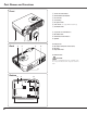
Part Names and Functions Front q w e r t y u Power Cord Connector Infrared Remote Receiver Zoom Lever Focus Ring Projection Lens Lens Cover (See page 50 for attaching.) Air Intake Vent i Top Controls and Indicators o Air Intake Vent !0 Terminals and Connectors !1 Speaker q Back w ert !6 y i u o !0 !2 Lamp Cover !3 Air Intake Vent (back and bottom) !4 Air Filter !5 Adjustable Feet !6 Exhaust Vent CAUTION Hot air is exhausted from the exhaust vent. Do not put heat-sensitive objects near this side.
Part Names and Functions Part Names and Functions Rear Terminal q w e t AUDIO IN R L (MONO) VIDEO COMPUTER IN 1 DVI - I ✽ r SERVICE PORT S-VIDEO y USB COMPUTER / COMPONENT RESET AUDIO IN AUDIO OUT MCI COMPUTER IN 2 / COMPONENT IN / MONITOR OUT Do not press this button. This button is used for optional accessories. q COMPUTER IN 1 DVI-I Connect output signal from a computer (Digital/Analog DVI-I type) to this terminal. (p17) w SERVICE PORT This jack is used to service this projector.
Part Names and Functions Top Control q w e r t y ON - OFF POWER INPUT SELECT VOLUME + AUTO SET UP VOLUME – WARNING LAMP REPLACE MENU o q AUTO SET UP button Correct vertical keystone distortion and adjust computer display parameters including Fine sync., Total dots and Picture position. (p24, 42) w INPUT button Select input source. (p27, 36 ) e POWER ON–OFF button Turn the projector on or off. (p20, 21) r SELECT button Execute the item selected.
Part Names and Functions Part Names and Functions q L-CLICK button Remote Control Act as left click for wireless mouse operation. (p13) w SIGNAL EMISSION indicator This indicator lights red while the laser beam is being emitted from the laser light window or a signal is being sent from the remote control to the projector. e AUTO PC button Operate the Auto PC Adjustment Function. (p29) q r D.ZOOM button Select the Digital zoom +/– mode and resize the image.
Part Names and Functions Laser Pointer Function This remote control emits a laser beam from the laser light window. With the LASER button pressed, laser light goes on. The signal emission indicator lights red and laser is emitted with red light. With the LASER button pressed for more than 1 minute or released, the light goes off. The laser emitted is a class II laser. Do not look into the laser light window or shine the laser beam on yourself or other people. Below are the caution labels for laser beam.
Part Names and Functions Part Names and Functions Wireless Mouse Operation The remote control can be used as a wireless mouse for your computer. Before operating the wireless mouse, connect your computer and the projector with the supplied USB cable. (See page 17 for connection.) When the Pointer function is used, the wireless mouse is not available. PRESENTATION POINTER button Move the pointer on the screen with this button.
Part Names and Functions Remote Control Code This projector has eight different remote control codes (Code 1 - Code 8). Switching remote control codes prevents remote control interference when operating several projectors or video equipment at the same time. Change the remote control code for the projector first before changing that for the remote control. See “Remote control” in Setting on page 46. 1 With holding down the MENU button, press the IMAGE button.
Installation Positioning the Projector This projector is designed to project on a flat projection surface and can be focused from 3.3’(1.0m) - 25.3’(7.7m). Refer to the figure and the table below for the screen size and the distance between the projector and the screen. A:B = 9:1 (Inch Diagonal) 25.3' (7.7m) 300” Max. Zoom 16.4' (5.0m) 12.5' (3.8m) 195” Min. Zoom 195” 8.2' (2.5m) 150” 100” 40” A 127” Installation 3.3' (1.
Installation Connecting the AC Power Cord This projector uses nominal input voltages of 100-120 V or 200-240 V AC. This projector automatically selects the correct input voltage. It is designed to work with single-phase power systems having a grounded neutral conductor. To reduce risk of electrical shock, do not plug into any other type of power system. Consult your authorized dealer or service station if you are not sure of the type of power being supplied.
Installation Connecting to a Computer Cables used for connection • VGA Cable (HDB 15 pin) ✽ • DVI-VGA Cable (HDB 15 pin) • USB Cable • Audio Cables (Mini Plug: stereo) ✽ (✽ = Not supplied with this projector.
Installation Connecting to Video Equipment Cables used for connection • Video and Audio Cable (RCA x 3) ✽ • S-VIDEO Cable ✽ • Audio Cables (Mini Plug: stereo) ✽ (✽ = Not supplied with this projector.
Installation Connecting to Component Video Equipment Cables used for connection • Audio Cables (Mini Plug (stereo) x 2 or RCA x 2) ✽ • Video and Audio Cable (RCA x 3) ✽ • Scart-VGA Cable ✽ • Component-VGA Cable ✽ (✽ = Not supplied with this projector.
Basic Operation Turning On the Projector 1 Complete peripheral connections (with a computer, VCR, etc.) before turning on the projector. 2 Connect the projector's AC power cord into an AC outlet. The POWER indicator blinks red in a moment and lights red. 3 Press the POWER ON-OFF button on the top control or on the remote control. The POWER indicator turns green lighting and the cooling fans start to operate. The preparation display appears on the screen and the count down starts.
Basic Operation Turning Off the Projector 1 Press the POWER ON-OFF button on the top control or on the remote control, and a message "Power off?" appears on the screen. 2 Press the POWER ON-OFF button again to turn off the projector. The POWER indicator starts to blink red, and it continues while the cooling fans are operating for about 90 seconds. (About 120 seconds when the fan mode is L2. See page 48.) 3 The message disappears after 4 seconds.
Basic Operation How to Operate the On-Screen Menu The projector can be adjusted or set via the On-Screen Menu. Refer to the following pages regarding each adjustment and setting procedure. On-Screen Menu Menu icon 1 Press the MENU button to display the On-Screen Menu. 2 Press the Point 7 8 buttons to select a Menu icon to adjust. Press the Point ed buttons to select an item to adjust. Pointer (red frame) Press the Point d button to move the pointer. 3 Press the SELECT button to show the item data.
Basic Operation Menu Bar For computer source Guide Window PC System Menu Image Select Menu Screen Menu Setting Menu Shows the selected Menu of the OnScreen Menu. Used to select computer system. (p28) Used to select an image level among Dynamic, Standard, Real, Blackboard(Green), and Image 1 ~ 4. (p32) Used to adjust size of image. [Normal / True / Wide / Digital zoom +/–] (p34) Used to change settings of the projector or reset lamp replace counter.
Basic Operation Zoom and Focus Adjustment Rotate the Zoom Lever to zoom in and out. Rotate the Focus Ring to adjust the projected picture focus. Zoom Lever Focus Ring Auto Setup Function Auto Set Up function is provided to automatically correct Keystone distortion according to the projector's tilt and adjust the computer display parameters (Fine sync, Total dots and Picture position) by just pressing the AUTO SET UP button on the top control or the AUTO SET button on the remote control.
Basic Operation Keystone Adjustment If a projected picture still has keystone distortion after pressing the AUTO SET UP button on the top control or the AUTO SET on the remote control, correct the image manually as follows: 1 Press the KEYSTONE button on the remote control or select Keystone in the Setting Menu (p42). The keystone dialog box appears. 2 Correct keystone distortion by pressing the Point ed78 button. Keystone adjustment can be memorized. (p42) Reduce the upper width with Point e button.
Basic Operation P-Timer Function Press the P-TIMER button on the remote control. The timer display “00 : 00” appears on the screen and the timer starts to count time (00 : 00 ~ 59 : 59). To stop the P-Timer, press the P-TIMER button. And then, press the P-TIMER button again to cancel the P-Timer function. Sound Adjustment Direct Operation indicates approximate level of volume. Volume Press the VOLUME +/– buttons on the top control or on the remote control to adjust volume.
Computer Input Input Source Selection Direct Operation Choose either Computer 1 or Computer 2 by pressing the INPUT button on the top control or press the COMPUTER button on the remote control. Before using these buttons, correct input source should be selected through menu operation as described below. INPUT button Computer 1 Computer 2 ✳ Video COMPUTER button Computer 1 Computer 2 ✳ ✳ See Note at the bottom of this page.
Computer Input Computer System Selection This projector automatically tunes to various types of computers based on VGA, SVGA, XGA or SXGA with its Multi-scan system and Auto PC Adjustment. If Computer is selected as a signal source, this projector automatically detects the signal format and tunes to project a proper image without any additional setting. (Signal formats provided in this projector is shown on page 59 ) ✔Note: The projector may display one of the following messages.
Computer Input Auto PC Adjustment Auto PC Adjustment function is provided to automatically adjust Fine sync, Total dots, Horizontal, and Vertical to conform to your computer. Auto PC Adjustment function can be operated as follows. Auto PC Adj. 1 Press the MENU button to display the On-Screen Menu. Press the Point 7 8 button to move the red frame pointer to PC Adjust Menu icon. 2 Press the Point d button to move the red frame pointer to Auto PC Adj. icon and then press the SELECT button twice.
Computer Input Manual PC Adjustment Some computers employ special signal formats which may not be tuned by Multi-scan system of this projector. Manual PC Adjustment enables you to precisely adjust several parameters to match those signal formats. The projector has 5 independent memory areas to memorize those parameters manually adjusted. It allows you to recall the setting for a specific computer. PC Adjust Menu icon 1 Press the MENU button and the On-Screen Menu will appear.
Computer Input Display area Select the resolution at the Display area dialog box. Press the SELECT button at the Display area icon and the Display area dialog box appears. Display area H Adjusts the horizontal area displayed by this projector. Press the Point 7 8 button to decrease/increase value and then press the SELECT button. Display area Display area V Adjusts the vertical area displayed by this projector. Press the Point 7 8 button to decrease/increase value and then press the SELECT button.
Computer Input Image Level Selection Direct Operation IMAGE button Select an image level among Dynamic, Standard, Real, Blackboard(Green), Image 1, Image 2, Image 3, and Image 4 by pressing the IMAGE button on the remote control. Dynamic Standard Dynamic Picture level suitable for viewing picture in a bright room. Standard Normal picture level preset on this projector. Real Blackboard(Green) Image 1 Real Picture level with improved halftone for graphics.
Computer Input Image Level Adjustment 1 Press the MENU button and the On-Screen Menu will appear. Press the Point 7 8 button to move the red frame pointer to the Image Adjust Menu icon. 2 Press the Point d button to move the red frame pointer to the item that you want to adjust, and then press the SELECT button. The level of each item is displayed. Adjust each level by pressing the Point 7 8 button.
Computer Input Screen Size Adjustment This projector has a picture screen resize function, which enables you to display the desirable image size. 1 Press the MENU button and the On-Screen Menu will appear. Press the Point 7 8 button to move the red frame pointer to the Screen Menu icon. 2 Press the Point d button and move the red frame pointer to the function that you want to select and then press the SELECT button.
Video Input Input Source Selection (Video, S-Video) INPUT button Direct Operation Video Choose Video by pressing the INPUT button on the top control or the VIDEO button on the remote control. Before using these buttons, correct input source should be selected through menu operation as described below. Computer 1 Computer 2 ✳ VIDEO button Video ✳ See Note at the bottom of this page. Input Menu icon Menu Operation 1 2 3 Input Menu Press the MENU button and the On-Screen Menu will appear.
Video Input Input Source Selection (Component, RGB Scart 21-Pin) Direct Operation INPUT button Computer 1 Choose Computer 2 by pressing the INPUT button on the top control or press the COMPUTER button on the remote control. Before using these buttons, correct input source should be selected through menu operation as described below. Computer 2 ✳ Video COMPUTER button Computer 1 Computer 2 ✳ ✳ See Note at the bottom of this page.
Video Input Video System Selection 1 Press the MENU button and the On-Screen Menu will appear. Press the Point 7 8 button to move the red frame pointer to the AV System Menu icon. 2 Press the Point d button to move the red arrow pointer to the system that you want to select and then press the SELECT button. Video or S-Video Auto The projector automatically detects incoming video system, and adjusts itself to optimize its performance. When Video System is PAL-M or PAL-N, select system manually.
Video Input Image Level Selection Direct Operation IMAGE button Dynamic Select a desired image level among Dynamic, Standard, Cinema, Blackboard (Green), Image 1, Image 2, Image 3, and Image 4 by pressing the IMAGE button on the remote control. Standard Dynamic Picture level suitable for viewing picture in a bright room. Standard Normal picture level preset on this projector. Cinema Blackboard(Green) Image 1 Cinema Picture level adjusted for the picture with fine tone.
Video Input Image Level Adjustment 1 Press the MENU button and the On-Screen Menu will appear. Press the Point 7 8 button to move the red frame pointer to the Image Adjust Menu icon. 2 Press the Point d button to move the red frame pointer to the item that you want to adjust and then press the SELECT button. The level of each item is displayed. Adjust each level by pressing the Point 7 8 button.
Video Input Progressive Interlaced video signal can be displayed in a progressive picture. Off . . . .Not activated. L1 . . . . .Select “L1” for an active picture. L2 . . . . .Select “L2” for a still picture. Image Level Menu Move the red frame pointer to an image icon to be set and then press the SELECT button. Film This function is effective on 3-2 pulldown video sources. With this function On, the projector reproduces pictures faithful to the original film quality.
Video Input Screen Size Adjustment This projector has a picture screen resize function, which enables you to display the desirable image size. 1 Press the MENU button and the On-Screen Menu will appear. Press the Point 7 8 button to move the red frame pointer to the Screen Menu icon. 2 Press the Point d button and move the red frame pointer to the function that you want to select and then press the SELECT button.
Setting Setting This projector has Setting menu that allows you to set up the other various functions described as follows; 1 Press the MENU button to display the On-Screen Menu. Press the Point 7 8 button to move the red frame pointer to the Setting Menu icon. 2 Press the Point d button to move the red frame pointer to the item that you want to set and then press the SELECT button. The Setting dialog box appears.
Setting Blue back Setting When this function is “On,” the projector produces a blue image while input signal is not detected. Display This function decides whether to display On-Screen Displays. On . . . . . . . shows all the On-Screen Displays. Off . . . . . . .
Setting Logo This function decides what to be displayed on the starting-up display as follows: User . . . . . .the image you captured Default . . . .the factory-set logo Off . . . . . . .count-down only Capture Capture This function enables you to capture the image being projected and use it for a starting-up display or interval of presentations. After capturing the projected image, go to the Logo function and set it to “User”.
Setting Standby mode Standby mode Setting This function is available when using an optional accessory attached to the DVI terminal, and it reduces standby energy when selecting Eco. Eco ···· reduces standby energy. Normal ···· consumes normal standby energy. Power management For reducing power consumption as well as maintaining the lamp life, the Power Management function turns off the projection lamp when the input signal is interrupted and no button is pressed for 30 seconds or more.
Setting Pointer Pointer You can emphasize a part of the projected image with this function. Choose either Spotlight or Pointer with the Point ed button and press the SELECT button. Then select one of three different sizes (Large, Middle, and Small) of Spotlight or a pointer of three different patterns (Arrow, Finger, and Dot) of Pointer. (See page 12 for operation.) Select Spotlight or Pointer with the Point ed button and press the SELECT button. Then select size or pattern with the Point 7 8 button.
Setting PIN code lock PIN code lock Setting This function prevents the projector from being operated by an unauthorized person and provides the following settings for security options. Off ...............the projector is unlocked with the PIN code. On1 .............requires to enter the PIN code every time turning on the projector. ...........
Setting Fan Fan This function provides you the following alternatives in the cooling fans operation after turning off the projector. (p21) L1 . . . . . . . .normal operation L2 . . . . . .slower operation than the normal (L1) , but takes longer to cool down the projector. In this mode, cooling time after turning off the projector will be extended longer than in the normal mode. Lamp counter reset This function is used to reset the lamp replace counter.
Maintenance and Cleaning Warning Indicator The WARNING indicator shows the state of the function which protects the projector. Check the state of the WARNING indicator and the POWER indicator to take proper maintenance. The projector is shut down and the WARNING indicator is blinking red.
Maintenance and Cleaning Cleaning the Air Filters Air filters prevent dust from accumulating on the surface of the optical elements inside the projector. Should the air filters become clogged with dust particles, it will reduce cooling fans’ effectiveness and may result in internal heat build up and adversely affect the life of the projector. Clean the air filters following the steps below. 1 Turn off the projector, and disconnect the AC power cord from the AC outlet.
Maintenance and Cleaning Cleaning the Projection Lens Follow these steps to clean the projection lens. Disconnect the AC power cord before cleaning. 2 Softly wipe the projection lens with a cleaning cloth that contains a small amount of non-abrasive camera lens cleaner, or use lens cleaning paper or a commercially available air blower to clean the lens. Avoid using an excessive amount of cleaner. Abrasive cleaners, solvents, or other harsh chemicals might scratch the surface.
Maintenance and Cleaning Lamp Replacement When the life of the projection lamp of this projector draws to an end, the LAMP REPLACE indicator lights yellow. If this indicator lights yellow, replace the lamp with a new one promptly. Top Control POWER WARNING VOLUME + This indicator lights yellow when the life of the projection lamp draws to an end. SELECT CAUTION LAMP REPLACE CAUTION Allow a projector to cool, for at least 45 minutes before you open the Lamp cover.
Maintenance and Cleaning Lamp Replace Counter Be sure to reset the lamp replace counter after the lamp is replaced. When the lamp replace counter is reset, the LAMP REPLACE indicator stops lighting. Turn the projector on, press the MENU button and the OnScreen Menu will appear. Press the Point 7 8 button to move the red frame pointer to the Setting Menu icon. 2 Press the Point d button to move the red frame pointer to the Lamp counter reset item and then press the SELECT button.
Appendix Troubleshooting Before calling your dealer or service center for assistance, check the items below once again. – Make sure you have properly connected the projector to peripheral equipment as described in "Connecting to a Computer", “Connecting to Component Video Equipment”and “Connecting to Video Equipment” on page17-19. – Make sure all equipment is connected to AC outlet and the power is turned on.
Appendix Some displays are not seen during the operation. – Check the Display item. (See “Setting” on page 43.) PIN code dialog box appears at start-up. – PIN code lock is being set. Input a PIN code (1234 or numbers you have set). (See “PIN code lock” on page 20 and 47.) Computer 2 cannot be selected. – Select Computer 2 at the Terminal item in the Setting Menu. (See “Setting” on page 44.) The Terminal item cannot be selected.
Appendix Menu Tree Computer Input / Video Input Input Computer 1 RGB( Analog ) Go to System (1) RGB( PC Digital ) N/A RGB( AV HDCP ) N/A RGB Computer 2 Video Sound Go to System (1) Component Go to System (2) RGB( Scart ) N/A Auto Go to System (3) Video Go to System (3) S-Video Go to System (3) ✽N/A - - - not applicable Sound Volume Mute Quit 0 - 63 On / Off Computer Input System (1) MODE 1 MODE 2 SVGA 1 ---- Image Select Dynamic Standard Real Blackboard(Green) Image 1 Image 2 I
Appendix Setting Video Input System (2) Auto 1080i 1035i 720p 575p 480p 575i 480i System (3) Auto PAL SECAM NTSC NTSC 4.43 PAL-M PAL-N Image Select Setting Language Auto setup Auto keystone Dynamic Standard Cinema Blackboard(Green) Image 1 Image 2 Image 3 Image 4 Store / Reset On / Off On / Off Logo PIN code entry Off On PIN code change Quit Logo Standby mode Off User Default Yes/No On / Off On / Off Computer 2 Monitor out Eco / Normal Contrast Brightness Color Tint Color temp.
Appendix Indicators and Projector Condition Check the indicators for projector condition. Indicators POWER WARNING LAMP REPLACE red/green red yellow Projector Condition The projector is OFF. (The AC power cord is unplugged.) • • • lights green. ✽ When ✽ The projector is preparing for stand-by or the projection lamp is being cooled down. The projector cannot be turned on until cooling is completed. ✽ The projector is ready to be turned on with the POWER ON-OFF button.
Appendix Compatible Computer Specifications Basically this projector can accept the signal from all computers with the V, H-Frequency mentioned below and less than 140 MHz of Dot Clock.
Appendix Technical Specifications Mechanical Information Projector Type Dimensions (W x H x D) Net Weight Feet Adjustment Multi-media Projector 11.73" x 2.8" x 8.58" (298mm x 71mm x 218mm) (Not including adjustable feet) 6.2 lbs (2.8kgs) 0˚ to 11.8˚ Panel Resolution LCD Panel System Panel Resolution Number of Pixels 0.
Appendix Accessories User's Manual AC Power Cord Remote Control and Batteries DVI-VGA Cable USB Cable Lens Cover with String and Screw Soft Carrying Bag PIN Code Label ● The specifications are subject to change without notice. ● LCD panels are manufactured to the highest possible standards. Even though 99.99% of the pixels are effective, a tiny fraction of the pixels (0.01% or less) may be ineffective by the characteristics of the LCD panels.
Appendix Configurations of Terminals COMPUTER INPUT/COMPONENT INPUT/MONITOR OUTPUT TERMINAL (ANALOG) Terminal : HDB15-PIN 4 5 10 15 14 2 3 9 8 13 1 7 12 6 11 1 2 3 4 5 6 7 8 Red (R/Cr) Input / Output Green (G/Y) Input / Output Blue (B/Cb) Input / Output ----Ground (Horiz.sync.) Ground (Red) Ground (Green) Ground (Blue) C1 C2 C3 C4 C5 Analog Red Input Analog Green Input Analog Blue Input Analog Horiz. sync Analog Ground (R/G/B) 1 2 3 4 5 6 7 8 T.M.D.S. Data2– T.M.D.S. Data2+ T.M.D.S.
Appendix PIN Code Number Memo Write down the PIN code number in the column below and keep it with this manual securely. If you forgot or lost the number and unable to operate the projector, contact the service station. PIN Code Lock No. Factory default set No: 1 2 3 4* Logo PIN Code Lock No. Factory default set No: 4 3 2 1* *Should the four-digit number be changed, the factory set number will be invalid. While the projector is locked with the PIN code...
CHRISTIE DIGITAL SYSTEMS, Inc. 809 Wellington Street North Kitchener, Ontario Canada N2G 4Y7 Telephone (519) 744-8005 North America call toll-free 1-800-265-2171 (sales) Fax (519) 749-3136 CHRISTIE DIGITAL SYSTEMS, Inc. 10550 Camden Drive Cypress, CA 90630 USA Telephone (714) 236-8610 Fax (714) 503-3385 Toll Free 1-800-407-7727 Toll Free 1-800-333-3816 Printed in Japan Part No. 10-A 610 319 8002 (1AA6P1P4777-- MT7K) CHRISTIE DIGITAL SYSTEMS, Inc. ViewPoint 200 Ashville Way Wokingham, Berkshire, U.K.