RPMX/CX50/CX60/CX67 User’s Manual Table of Contents Contents Page 1 INTRODUCTION 1.1 Overview..................................................................................................... 1-1 1.2 Components ................................................................................................ 1-2 1.3 Purchase Record and Servicing .................................................................. 1-3 2 SOURCE SETUPS 2.1 Source Connections ..............................................
Section 1 Introduction 1.1 Overview The GraphXMASTER X-series includes the RPMX-100U (38-GFX101-xx), CX50-100U (38-GFX003-xx), CX60-100U (38-GFX004-xx) and CX67-100U (38-GFX005-xx). All of these products are based on single-chip DLP (Digital Light Processing) technology with XGA resolution. The RPMX-100U (Rear Projection Module) is specially designed for rear screen projection..
Section 1: Introduction How the projector works The projector operates based on DLP technology by Texas Instruments. An external source provides the necessary XGA input signals accepted by the projector. An internal 120W UHP lamp generates light, which then travels through a rotating color wheel alternately passing red, green and blue light to the single 0.7" imaging panel (also called a digital micromirror device or DMD).
Section 1: Introduction 1.3 Purchase Record and Servicing Whether the projector is under warranty or the warranty has expired, Christie’s highly trained and extensive factory and dealer service network is always available to quickly diagnose and correct projector malfunctions. Service manuals and updates are available to service technicians for all projectors. If you encounter any problems with the projector and require assistance, contact your dealer or Christie.
Section 2 Source Setup Introduction 2.1 Source Connections This section provides details on how to connect various external sources to the projector. All connections are made to the main input panel of the Electronics Module (EM). It is recommended that you connect your sources before powering up the projector. RGBHV (5 BNCs) ' The top input interface provides 5 BNC connectors for connecting to a variety of sources such as VGA, SVGA, XGA, SXGA, Mac, PowerMac, DEC, Sun, SGI and others.
Section 2: Source Setup Analog VGA Signals ' Connect Analog VGA signals to the 15-pin HD D-sub connector on the second input interface. Figure 2.2. Figure 2.2. Analog VGA Connector DVI Digital Video Signals ' The second input interface is dedicated to digital video input signals conforming to the DVI (Digital Visual Interface) standard.
Section 2: Source Setup Figure 2.4. Loop Digital Video Input Signals Composite Video ' Connect a composite video input to the Composite RCA jack labeled IN. The jack adjacent to it is left empty, unless you want to loop the composite video signal through to the next display device. Figure 2.5. Figure 2.5.
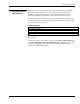
Section 2: Source Setup Composite Video Loop Through From your source, connect a composite video source signal to the Composite IN RCA jack. Take a second cable and connect it from the empty RCA jack labeled Composite OUT to the Composite IN connector of the next projector. Continue connecting projectors in this manner – the last projector will have an empty Composite OUT connector. Figure 2.6. Figure 2.6.
Section 2: Source Setup Figure 2.8. S-Video Loop Through 2.2 Serial Port Connections There are two, 9-pin DIN connectors on the input panel dedicated to serial communication. These connectors allow you to connect your projector to an external controlling device with a serial interface, such as a personal computer, for the purpose of communicating without having to use the keypad.
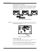
Section 2: Source Setup Figure 2.10. Multiple Projector RS-232 Connection Figure 2.11. Multiple Projector RS232 Communication Schematic Figure 2.12.
Section 2: Source Setup 2.3 Power Connection There are two AC receptacles on the EM. To plug in a single projector, plug the power cord into the top AC receptacle (labeled INLET). Then plug the 3-pronged end of the power cord into a grounded AC outlet. If you want to connect multiple projectors (up to a maximum of 4), connect a second power cord to the AC receptacle (labeled OUTLET) on the left side of the first projector and the other end to the AC receptacle (INLET) of the next projector.
Section 3 Operation This section provides a general description of the projector’s main components. It also provides details on the projector’s software menu system. 3.1 Projector Overview The modular design of the projector allows the user to access and service specific components of the projector, such as the lamp, quickly and easily without having to disassemble the entire projector. Figure 3.1.
Section 3: Operation Electrical Module (EM) ' The EM is the main control unit of the projector. It is mounted independently from the PHM to the mounting tray. It is the module where all source connections are made and where the main power switch is located. The EM contains the majority of PCB’s, such as the Control PCB, BNC Input PCB, Video Input PCB and Control RS-232C PCB. In general, these boards are responsible for the video processing and communication requirements of the projector.
Section 3: Operation 3.2 Using the Keypad The projector is controlled by an IR remote keypad that is supplied in the User’s Kit. It is operated by 2 AA batteries and provides wireless control of the projector from up to 100 feet away. Keep in mind the batteries will require replacement over time. If the projector is not responding to keypad entries and there isn’t an obstruction of the IR sensor, it may indicate the batteries require replacement.
Section 3: Operation NOTES: 1) Avoid turning the projector on and off without waiting at least 52 seconds in between. In general, hot re-strikes reduce lamp life. 2) It is recommended that you do not unplug the projector until the cooling fan is off – the FAN LED will no longer be illuminated. STANDBY Press STANDBY to blank the display while keeping the projector in a warmed-up and ready state.
Section 3: Operation PROJECTOR Press Projector to access options for communication with a specific projector or all projectors within a network. All Projectors – You can toggle the setting for this option using the Enter key. Set All Projectors to YES if you have a single stand-alone unit or want to enable broadcast control to multiple projectors in a network. In this case, when you send a command using the IR keypad all projectors will respond.
Section 3: Operation Navigating the Menus ' Most of the controls for the projector are accessed from within the projector’s menu system. The Main Menu is accessible by pressing the Menu key on the remote keypad. This menu is accessible at any time during operation. From it you can access various other “submenus” with related functions. Figure 3.2. Accessing the Main Menu To select a submenu, use the ON OFF keys to highlight the desired option and press Enter .
Section 3: Operation DIRECT SLIDEBARS There are a set of direct keys available on the keypad that allow you to quickly access often used slidebars without having to travel the menu system. For example, simply press Contrast to immediately display the same contrast slidebar as if selected from the Image Settings menu.
Section 3: Operation Size and Position ' Use the options in the Size and Position menu (Figure 3.4.) to adjust the size of the displayed image so that it fits the screen to best suit the application. Other related options, such as Pixel Track and Pixel Phase are used to refine the image. Figure 3.4.
Section 3: Operation NO RESIZING Select No Resizing to display the image in its native resolution. The values for the options in the top level Size and Position menu will change accordingly. Figure 3.7. No Resizing FULL SCREEN Select Full Screen when you want to display the image using all the pixels available regardless of the source and original aspect ratio. FULL WIDTH Select Full Width when you want to fill the screen from left-to-right.
Section 3: Operation Tiling Full Screen, Tiling Full Width, Tiling Full Height and Tiling Anamorphic. These options are essentially the same as the ones described above except they expand across displays in the defined array. See 3.7 Using Multiple Projectors later in this section. Figure 3.9. “Tiled” Resize Presets “CUSTOM” RESIZE PRESETS Custom appears in the list of available resize presets as an unnumbered option.
Section 3: Operation to the point where one large stripe fills the image. Again, the image may still exhibit some noise. NOTE: 1) By default, the projector will sample at the correct frequency for most sources. 2) Not available for video sources. 3) SHORT CUT: Press Pixel and adjust the top slidebar. Pixel phase Use this option to adjust the phase of the pixel sampling clock relative to the incoming signal. It is used primarily for adjusting RGB inputs.
Section 3: Operation Contrast Select Contrast when you want to increase or decrease the perceived difference between light and dark areas of your image (0-255). If contrast is set too high, the light parts of the image loses detail and clarity. If the value is set too low, the light areas will not be as bright as they could be and the resulting image will appear dim. Start low and increase so that whites remain bright but are not distorted or tinted, and that light areas do not become white (i.e.
Section 3: Operation test pattern is displayed. NOTES: 1) This option is only available when using a video source. 2) This option is not available when using an internal test pattern. DETAIL Detail adjusts the sharpness of the video image. Use or until the display is as sharp as possible, keeping in mind that any level of detail above 3 (default) increases the level of detail as well as introduce some level of noise in the image. Set below 3, to filter the signal and remove noise from a noisy source.
Section 3: Operation To create or adjust a user defined (custom) color temperature: NOTE: Use an external test pattern when adjusting color temperature. (Figure 3.13.) 1. Select User1 or User2 and adjust Red, Green and Blue slidebars until the desired color temperature is achieved. 2. Exit the menu to save settings. Figure 3.13.
Section 3: Operation “crushed” nor excessively elevated. By default, the projector automatically determines the correct setting according to the type of incoming video signal: • 0 IRE – Select this setting for DVD output with “enhanced black”, SECAM, most PAL standards, and Japanese NTSC. • 7.5 IRE – Select this setting for most NTSC video signals. Figure 3.15. Input Video Black NOTE: You can override the setting for some types of video.
Section 3: Operation BLACK LEVELS & INPUT DRIVES An experienced user can manually adjust the black levels and input drives for a source that exhibits high black levels. By adjusting the slidebars here, you can refine the image source input levels. NOTE: Input levels are of limited use with digital signals. To check an image and manually adjust black levels and input drives: 1. Make sure overall Contrast and Brightness (in Image Settings) are both set close to mid-range. 2.
Section 3: Operation White Boost This option allows you to recapture some of the lost light from the transition between segments in the color wheel when it is spinning. Use the slidebar to increase the value of White Boost from 0 to 10. When set to a value of “0” the option is OFF. As you increase the value, you will notice the image becomes slightly brighter and a little less saturated. NOTE: It is recommended Auto Setup and Auto Input Levels be adjusted prior to applying White Boost for new sources.
Section 3: Operation Configuration ' From the Configuration menu, you can access various options and submenus that allow you to customize how you view and use your projector, such as menu location and language. You can also assign a projector ID number and define its location in a multiple display wall. Other options provide you with the ability to adjust primary colors and select various internal test patterns. Figure 3.20.
Section 3: Operation Menu Preference Select this option when you want the menus to appear in a different location on the screen. By default, the menus appear in the top left corner of the screen. You can adjust the menu location vertically and horizontally by selecting and adjusting the slidebars, as described below. (Figure 3.23.) Figure 3.23. Menu Preferences MENU H-POSITION Adjust this slidebar to move the menu from left-to-right. The higher the value the further right the menu will move.
Section 3: Operation PROJECTOR ID Use this option to set a specific 2-digit ID number for the projector. In a network environment, having the ability to control one or all projectors is very important. Assigning ID numbers to each projector in a network allows you to do this. To assign an ID number using the option in the Communications menu, select the option Projector ID. Press Enter twice until you see two dashed lines, “- -”.
Section 3: Operation start numbering in the top-left corner (this display will be 1,1) and work across and down until you reach the bottom right corner. See Figure 3.26. PROJECTOR ID This is a read only item that shows the ID of the projector for which you are defining its location in the Tiling Setup menu. See Figure 3.26., item 5. RESIZE PRESETS This is the same option that appears in the Size and Position menu. It appears again here for convenience. Figure 3.27.
Section 3: Operation Diagnostics & Service Select this submenu to access various internal test patterns and/or freeze the displayed image for diagnostic and setup purposes. TEST PATTERN Nine internal test patterns are available from this menu. You can highlight and press Enter to select a desired test pattern or you can cycle through the available patterns using the direct key Test P on the keypad. For each key press made, another test pattern appears.
Section 3: Operation 3.4 The Lamp Menu At any time during operation you can select the Lamp Menu to view the number of hours the lamp has been in use. Typically, as the lamp ages it begins to get dimmer. It is recommended that you check the number of hours the lamp has been in use as a good indicator as to whether or not it requires replacement. Other lamp specific read-only information includes the Lamp S/N (lamp serial number). Figure 3.32.
Section 3: Operation Figure 3.33. 3.5 System Status This is a read-only window accessible from the Main menu that lists system information, such as projector model and serial number, projector ID, current input source, resolution, frequencies and current software version. Figure 3.34. Status Menu 3.
Section 3: Operation 3.7 Using Multiple Projectors There are two methods of communicating with multiple projectors, using the IR keypad or RS-232 serial communication. These methods are not interchangeable. It is recommended that you choose the method which will best suit your installation and setup your network for this type of communication. For details on how to operate the projector using RS-232 commands, go to www.christiedigital.
Section 3: Operation Defining the Size of ' Use the Tiling Setup submenu to define the size of a wall (number of rows and a Display Wall columns), and identify the location of each projector in the wall. If you are operating a stand-alone unit, enter “1” for items 1 to 4. Figure 3.35. Matching Colors of ' For the image on a display wall to appear seamless, color and brightness must be Multiple Projectors precisely matched from screen to screen.
Section 3: Operation • • Wait for the 6 values (black levels and drives) to stabilize. Leave the Input Levels menu. Input levels should now be correct for the source. Step 2: Enable Primary Color Adjustment In the Adjust Primary Colors menu, select APC Enable, highlight and select Enable to enable the option so that primary colors controls can be adjusted and applied to the image.
Section 3: Operation 4c) Adjust color temperature to match whites between screens (keep White Boost at 0) – View all white fields and adjust Red, Green, Blue in the Color Temperature window. When matching light output of individual projectors it may be necessary to adjust the White Boost level. Start with White Boost at 0 and match to the dimmest display. Figure 3.38. Step 5: Re-adjust Input Levels, if necessary - “fine-tune” input black levels to match grey scale color.
Section 3: Operation attention of a qualified service technician. The specific pattern of flashing indicates the 2-digit code identifying the type of problem encountered—the number of yellow flashes represents the first digit and the number of red flashes indicates the second digit. Consult Table 3.2 for a description of the error. Press Exit on the keypad to acknowledge the error - the POWER LED will stop flashing and go to a solid green color.
Section 4 Maintenance 4.1 Warnings and Guidelines The projector is an international regulatory agency approved product designed for safe and reliable operation. To assure complete safety at all times it is important to acknowledge the following precautions while operating the projector. WARNING Never look directly into the projector lens. The extremely high brightness of this projector can cause permanent eye damage.
Section 4: Maintenance and Troubleshooting stops, excessive force, and uneven surfaces may cause the projector and cart combination to overturn. Lamp ' The projector is designed to operate with a 120W UHP lamp. A lamp that has reached the end of its life or has failed should be replaced with a good lamp as soon as possible. WARNING Turn off the projector before replacing a lamp. Wait approximately 5 minutes to allow the lamp to cool before removing.
Section 4: Maintenance and Troubleshooting Ventilation ' Slots and vents in the projector provide ventilation. Never block or cover these openings. This ensures reliable operation of the projector and prevents overheating. Do not place the projector over a radiator or heat register. The projector should not be placed in an enclosure unless proper ventilation is provided. Do not “poke” objects into the ventilation openings of the projector.
Section 4: Maintenance and Troubleshooting Replacing Keypad ' Batteries The keypad works on 2 AA size alkaline batteries. Periodically these batteries require replacement. To replace batteries: 1. Turn the keypad over to access the small battery compartment cover. 2. Push the small tab in and up at the same time - lifting the cover completely off. 3. Remove and discard the old batteries from keypad. 4.
Section 4: Maintenance and Troubleshooting STEP 1 – Power down the projector and unplug – Press Power to turn the projector off. Allow the fans to stop before unplugging it from the AC outlet. WARNINGS It is recommended that you allow the lamp to cool for approximately 5 minutes before removing it from the lamp module. STEP 2 – Access the lamp module (a) Loosen the 2 screws securing the lamp door to the side of the PHM module. (Figure 4.1.) Figure 4.1. (b) Swing the lamp door open. (Figure 4.2.
Section 4: Maintenance and Troubleshooting Figure 4.3. (b) Firmly, grasp the lamp module and pull straight out. Keep the lamp level when doing this so that it easily disconnects from the terminal block. (Figure 4.4.) Figure 4.4. STEP 4 – Install a new lamp (a) Slide the new lamp into the lamp module so it fully connects into the terminal block. (b) Turn the lock ring to the LOCK position.
Section 4: Maintenance and Troubleshooting 4.4 Projection Lens Focus The projection lens can be adjusted to focus a displayed image. Typically, the projection lens only requires focusing during the installation and setup of the projector. Do not look directly into the projection lens when adjusting for focus. For RPMX (38-GFX101-01), CX67 (38-GFX005-01): (Figure 4.5.) 1. Loosen the lock screw (C) on the lock ring (A). 2. Loosen the lock ring (A), until the lens barrel (B) can easily be turned. 3.
Section 4: Maintenance and Troubleshooting 4.5 Troubleshooting Use the following as a guide in identifying general operating problems, the cause and how they can be corrected. Most of these problems can be corrected by a user and do not require the assistance of a qualified technician. Problems that are more technically related do require the attention of a qualified technician. These are identified in the service manual. Symptom ' The projector does not power on when the Power key is pressed. 1.
Section 4: Maintenance and Troubleshooting Symptom ' The display is jittery or unstable… 1. If the display is jittery, or if it disappears and reappears erratically check that the source is properly connected and that its signal is of adequate quality for detection. For example, if the projector scans the default input for a signal to display, and poor quality or a source is improperly connected, the projector briefly and repeatedly attempts to display an image.
Section 4: Maintenance and Troubleshooting Symptom ' The display is not sharp or clean… 1. More display adjustments may be required – focus, brightness, contrast, pixel tracking, and pixel phase. 2. If you are using a BNC T-connector, try using a distribution amplifier to boost signal levels. 3. The source input signal may be of low quality. Try another source. CAUSE/REMEDY: Symptom ' Colors in the display are inaccurate… 1. The color, gamma, and color temperature settings may require adjustment.
Section 5 Specifications NOTES: 1) Due to continuing research, specifications are subject to change without notice. 2) Specifications apply to all models unless otherwise noted. 3) CX50/CX60 data with use of High Gain screen and CX67 with Wide Angle screen. 4) CX50/ CX60/CX67 screens are sold separately.
Section 5: Specifications Sync (interlaced or progressive scan formats) Horizontal frequency range 15-85 kHz Vertical frequency range 50-85Hz Scan format Interlaced or progressive Sync types Separate H and V Composite Sync-on-green Nominal impedance 75 ohms Polarity (N/A to sync-on-green) positive or negative DC operating range 0-5V Composite Video and S-Video (requires optional Video Decoder Module) Signal formats Composite video (CVBS), S-Video (Y/C), Video standards NTSC, NTSC 4.
Section 5: Specifications Viewing Angle ' FOR CX50-100U Horizontal (to half gain) Vertical Power Requirements ' ± 38 degrees ± 2.0 degrees ± 9.5 degrees ± 1.0 degrees FOR CX60-100U Horizontal Vertical ± 25 degrees ± 3.0 degrees ± 9 degrees ± 1.0 degrees FOR CX67-100U Horizontal Vertical ± 35 degrees ± 3.0 degrees ± 35 degrees ± 3.0 degrees Voltage range Line frequency Inrush current 100 - 240 VAC 50 Hz – 60 Hz nominal 65A max @120V 135A max @ 240V 2.5A @ 100V (typical), 1.
Section 5: Specifications Physical Characteristics ' NOTE: 1) Dimensions apply to all models, unless specified otherwise. 2) Screen dimensions can vary based on environmental conditions.3) All dimensions in inches and for reference only. Adjuster in nominal position. For RPMX-100U (38-GFX101-01) ' Weight (including adjuster) < 44lb. shipping weight includes packaging <100lb.
Section 5: Specifications For RPMX-100U (38-GFX101-05) ' Size (includes lens, adjuster and mounting rails) Lens Horizontal Configuration (0 degree) Lens Vertical Configuration (90 degree) RPMX/CX50/CX60/CX67 User’s Manual 5-5
Section 5: Specifications Weight (without screen, top For CX50-100U (38-GFX003-xx) ' cover, pedestal and packaging) Size 125lb. Weight (without screen, top For CX60-100U (38-GFX004-xx) ' cover, pedestal and packaging) Size 150lb.
Section 5: Specifications Weight (without screen, top For CX67-100U (38-GFX006-xx) ' cover, pedestal and packaging) Size Safety and ' Regulatory Compliance 171lb. CAN/CSA C22.2 No. 60950-00 ANSI/UL 60950 3rd Edition EN60950: 2000 European Norm, Safety of Information Technology Equipment Electro-Magnetic Compatibility (E.M.
Section 5: Specifications Accessories (optional) ' • User’s Kit (38-804828-01 for RPMX) and (38-804829-02 for CX50 / CX60 / CX67), includes user/installation manuals, IR remote with batteries, assorted ball drivers • High Gain Screen (38-804810-01 for CX50) and (38-804811-02/03 for CX60) • Wide Angle Screen (38-804832-02 for CX67) • Pedestal Kit (38-804802-02 for CX50, 38-804814-02 for CX60, 38-80483102 for CX67) • Pedestal Side Panel Kit (38-804803-01 for CX50, 38-804818-01 for CX60, 38-804835-01 for CX67
Appendix A Glossary This appendix defines the specific terms used in this manual as they apply to this projector. Also included are other general terms commonly used in the projection industry. Active Line Time ' The time, inside one horizontal scan line, during which video is generated. Ambient Light Rejection ' The ability of a screen to reflect ambient light in a direction away from the "line of best viewing". Curved screens usually have good ambient light rejection.
Appendix A: Glossary Checkbox ' A menu item that indicates whether an option is currently in effect (checked) or not (unchecked). Color Shift ' A change in the tint of a white field across an image. Color Temperature ' The coloration (reddish, white, bluish, greenish, etc.) of white in an image, measured using the Kelvin (degrees K) temperature scale. Higher temperatures output more light. Component Video ' See YCbCr or YPbPr.
Appendix A: Glossary Help Screen ' A display of help information regarding the current task or presentation. Horizontal Frequency ' The frequency at which scan lines are generated, which varies amongst sources. Also called horizontal scan rate or line rate. Horizontal Offset ' The difference between the center of the projected image and the center of the projector lens.
Appendix A: Glossary Menu ' A list of selectable options displayed on the screen. NTSC Video ' A video output format of some video tape and disk players. There are two types of NTSC (National Television Standards Committee) video: NTSC 3.58 and NTSC 4.43. NTSC 3.58 is used primarily in North America and Japan. NTSC 4.43 is less commonly used. Optical Screen ' A type of rear-projection screen which re-directs light through the screen to increase image brightness in front of the screen.
Appendix A: Glossary RGB Video ' The video output (analog or digital) of most computers. Analog RGB video can have 3, 4, or 5 wires — one each for red, green, and blue, and either none, one or two for sync. For three-wire RGB, the green wire usually provides sync. (See TTL Video). RS-232 ' A common asynchronous data transmission standard recommended by the Electronics Industries Association (EIA). Also called serial communication.
Appendix A: Glossary Variable Scan ' The ability of a projector to synchronize to inputs with frequencies within a specified range. Vertical Frequency ' The frequency at which images are generated. Vertical frequencies vary amongst sources. Also called vertical scan rate. Vertical Offset ' The difference between the center of the projected image and the center of the projector lens.
Appendix B Acceptable Signal Types Format Type Mode H. Freq V. Freq Input Sync Scan Type Resolution polarity Input Terminal NTSC@RGBHV NTSC 15.734 59.94 N/N Interlaced RGB IN PAL/SECAM @RGBHV PAL 15.625 50.00 N/N Interlaced RGB IN HDTV@RGBHV HDTV 33.75 60.00 N/N Interlaced RGB IN NEC PC98 Std @56Hz NEC24k 24.82 55.90 640X400 N/N Non-Interlaced RGB IN VGA Graphics 350 lines @70Hz TEXT70 31.47 70.
Appendix B: Signal Types Format Type Mode H. Freq V. Freq Input Sync Scan Type Resolution polarity Input Terminal VESA 800X600 @85Hz SVGA85 53.674 85.061 800X600 P/P Non-Interlaced RGB IN MacIntosh 16inch Mode @75Hz MAC16 49.725 74.550 832X624 -/- Non-Interlaced RGB IN VESA 1024X768 @43Hz XGA43 35.522 43.479 1024X768 P/P Interlaced RGB IN VESA 1024X768 @60Hz XGA60 48.363 60.004 1024X768 N/N Non-Interlaced RGB IN VESA 1024X768 @70Hz XGA70 56.476 70.
Appendix B: Signal Types Mode Input Res. A Pixel B C D E FH KHz fV Hz Clock MHz NTSC 15.734 59.94 16.521 PAL 15.625 50 16.406 HDTV 33.75 60 67.264 G Line H I J K NEC24k 640X400 85 640 59 64 848 24.82 55.9 21.047 25 400 7 8 440 TEXT70 640X350 48 640 14 96 800 31.47 70.09 25.176 60 350 38 2 449 TEXT70 640X400 48 640 14 96 800 31.47 70.09 25.176 35 400 13 2 449 TEXT70 720X350 54 720 18 108 900 31.47 70.09 28.
Appendix C Keypad Reference RPMX/CX50/CX60/CX67 User’s Manual C-1
Appendix D Serial Communication Cables When connecting projector to a computer or another projector use the appropriate serial communication shielded cabling as illustrated.
Appendix D: Serial Communication Cables D-2 RPMX/CX50/CX60/CX67 User’s Manual
Appendix E Menu Tree RPMX/CX50/CX60/CX67 User’s Manual E-1
Index F 6 6-Axis Adjuster, 3-2 Freeze Allowed, 3-22 Freeze Image, 3-22 Freeze Key, 3-5 A Adjust Primary Colors, 3-21 Arrow Keys, 3-4 Auto Input Levels, 3-17 Auto Setup, 3-17, 3-24 B Baud Rate, 3-19 Black level, 3-16 Brightness Key, 3-4, 3-12 C Color, 3-12 Color and Uniformity, 3-21 Color Setup, 3-12 Color Temperature, 3-21 Creating custom, 3-14 Custom, 3-13 color wheel, 2-2 Components, 2-2 Composite Video, 2-3 Configuration Menu, 3-18 Connect Source DVI Digital Video, 2-2 Connect Sources Analog VGA, 2-2 C
Index Menu Preferences, 3-19 Mode Memory Status, 3-17 P Pixel Key, 3-5 Pixel Phase, 3-11 Pixel Tracking, 3-10 Position Key, 3-5 Power Connection, 2-7 Power Cords, 4-2 Power Level Switching, 3-23 Power Warning, 4-2 Presentation Level Definition, 3-3 Projection Lens, 4-7 Projector Cleaning/Maintenance, 4-3 Service, 4-3 Projector Head Module (PHM), 3-1 Projector ID, 3-20 Assigning, 3-20 Purchase Record and Servicing, 2-3 R Resize Image, 3-8 Anamorphic, 3-9 Custom, 3-10 Full Height, 3-9 Full Screen, 3-9 Full Wi