
Operator`s manual


5
CHRISTIE DIGITAL SYSTEMS 5-1
August 7, 2003
5. ALIGNMENT AND CHECKOUT PROCEDURES
5.1. MECHANICAL ALIGNMENT
When installing an SLC console equipped for 35/70 mm operation, be certain
that the optical bench assembly is in the correct sliding position: FORWARD
for 70 mm, to the REAR for 35 mm. Contact Christie for more information or
for assistance.
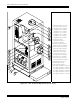
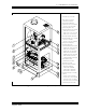
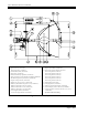
All SLC Consoles are optically aligned at the factory. The optical bench or plenum assembly
is aligned with an optical laser alignment tool. At installation, if not already mounted, the
projector must subsequently be mechanically aligned to the console snood. This is done by
adjusting the jackscrews on the projector mounting bracket (Up/Down, Left/Right). (See
Item 14 in Figure A-2.)
A satisfactory mechanical alignment can readily be obtained without the use of any special
tools.
5.2. INSTALLATION OF XENON LAMP
WARNING
Authorized protective clothing must
be worn when protective cover is
removed from lamp.
1. Turn off all AC power.
2. Open top door on the operating (right) side of console.
3. Remove plenum access cover.
4. Verify that lamp model number and rating correspond to the rating on the console
nameplate or lamp rating sticker.
5. Remove lamp from package.
WARNING
Do not touch the quartz body of the lamp with bare hands at any time.
Do not apply any bending or twisting force to the quartz body of the
lamp.