CP2000-X USER MANUAL 020-100031-01
Table of Contents 1 Introduction 1.1 The Projector ............................................................................................................. 1-1 1.2 List of Components ................................................................................................... 1-3 1.3 Purchase Record and Service Contacts ..................................................................... 1-4 1.4 Ethernet Settings for This Projector ..............................................................
TABLE OF CONTENTS 8 Specifications 8.1 Specifications ............................................................................................................8-1 Appendices A Glossary ...................................................................................................................... A-1 B ASCII Messages ......................................................................................................... B-1 C System Integration ................................................
Section 1 Introduction 1.1 The Projector The CP2000-X is a professional quality, easyto-use split-body DMD projector utilizing 3-chip Digital Light Processing (DLP) Cinema technology from Texas Instruments. Its unique separation of projection head and lamp ballast means both parts can be installed with greater ease, providing the ideal solution for tight spaces and challenging rig-and-fly CP2000-X PROJECTOR rental/staging installations.
INTRODUCTION Can be rigged, flown and/or stacked with adjustable FredFrame rigging hardware Choice of 4 Xenon bubble lamp sizes and ratings Universal 3-phase 7 kW switching ballast for all lamps and countries Screen brightness: Up to 14 fL on 25 meter screen (6 kW lamp) or 17 meter screen (3 kW lamp) Achievable contrast ratio 2000:1 full field on/off in center.
INTRODUCTION 1.2 List of Components The following components make up a complete CP2000-X system (see Figure 3.1): Projection Head. Includes: Line cord Touch Panel Controller with mounting hardware and 3-ft. cable Standard and high-security keys for lamp and igniter service access, plus assorted Allen keys CP2000-X User’s Manual Lamp Ballast (three-phase 7 kW for all lamps in all countries) Choice of lamp kit (incl. protective gear) Cable kit (incl.
INTRODUCTION 1.3 Purchase Record and Service Contacts Whether the projector is under warranty or the warranty has expired, Christie’s extensive and highly trained factory and dealer service network is always available to quickly diagnose and correct projector malfunctions. Complete service manuals and updates are available to service technicians for all projectors.
Section 2 Installation & Setup This section explains how to install, connect, and optimize the projector. NOTE: Unless otherwise specified, illustrations apply for either CP model and may not always show the rear-mounted TPC. 2.1 Quick Setup Follow these steps for quick setup of the projector in a basic front mount position. STEP 1 Position the Projection Head Locate the projection head at an appropriate throw distance (projector-to-screen distance) and vertical position. See 2.
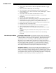
INSTALLATION & SETUP Connect a Source Connect your desired source to the appropriate HD-SDI (cinema) connector(s) on the Communications and Source Connection Panel at the rear of the projector. NOTE: To connect other types of sources, such as alternative Figure 2.2. Access to Cinema and Noncontent through DVI or Cinema Ports Christie’s Cine-IPM 2K, you must remove the access panel located on the underside of the projector near the air filter. Drill an exit hole or leave the panel off.
INSTALLATION AND SETUP HEAD-TO-BALLAST: Connect all 4 ballast cables—two DC power cables, and 2 communication/control cables—between the projector rear and lamp ballast. BALLAST-TO-AC: See Figure 2.4. Connect the ballast’s integral line cord to your AC supply (you may have to first modify the plug for the AC at your site).
INSTALLATION & SETUP HEAD-TO-AC: Connect the Christie-supplied IEC 320 (220V) 15-amp line cord to a single phase 208V AC supply. Do not substitute other cords. Input power required is 200 - 240 VAC (±10%), 50 to 60 Hz @ 3 amps for 208 V. WARNING Do not attempt operation if the AC level is not within the specified voltage and power range for the projection head (180-265 AC). Figure 2.5. Connecting Projection Head to AC Supply EXTRACTOR: Also plug the extractor fan into the projector. See 2.
INSTALLATION AND SETUP uch Panel To Controller Before powering up the projector and igniting the lamp, the installer must define in projector memory the size of lamp installed, otherwise you risk severely overdriving or underdriving a lamp. SET THE LAMP TYPE: At the TPC, go to the Admin: Lamp menu (password required). Enter the size of the lamp currently installed in the projector (factory default = 2.0 kW). See Section 3, Operation if you need help using the TPC menus.
INSTALLATION & SETUP Figure 2.7. Audience Coverage with a Flat Screen NOTE: CP2000-X high-contrast lenses are designed primarily for use with flat screens, but the projector’s depth-of-field range allows the lens to be focused on mildly curved screens as well. While focus remains sharp in the corners, there may be significant pincushion distortion, primarily at the top of the screen. Rear Screen Installations There are two basic types of rear screens: diffused and optical.
INSTALLATION AND SETUP Table 2.1. Matching Lenses to Screen Size Lens Type Screen Width (<—>) 1.25 – 1.45:1 zoom 10-121 ft. 1.45 – 1.8:1 zoom 8-102 ft. 1.8 – 2.4:1 zoom 6-83 ft. 2.2 – 3.0:1 zoom 5-66 ft. 3.0 – 4.3:1 zoom 3-49 ft. 4.3 – 6.0:1 zoom 2.5-35 ft. 5.5 – 8.5:1 zoom 2-27 ft. Screen Aspect Ratio Aspect ratio describes the proportion of the display and is expressed as the ratio of width to height, such as “5:4” or “16:9”. Typical aspect ratios range from 1.25 to 2.
INSTALLATION & SETUP vertically—enough to utilize the remaining pixels while not noticeably distorting the image. Displaying Both ‘Flat” and “Scope” As an example, two standard types of displays common in theatres—flat and scope— differ in their width-to-height aspect ratio as shown below: Figure 2.9.
INSTALLATION AND SETUP the screen size and lens type you are using. Make sure that the room can accommodate the required location of the projector for the chosen screen size. Positioning at a With the projection head secured on a suitable cart, position the unit so that the front bezel is less than 2 feet from the theatre’s port window wall, or 3 feet if the optional Port Window auxiliary lens mount will be added. Center the projector with the theatre screen () if possible (see Figure 2.10 A).
INSTALLATION & SETUP Figure 2.11. Estimating Throw Distance: Example As shown in Figure 2.10, throw distance is approximately equal to the full horizontal width of the screen multiplied by the type of lens you are using. For example, if you are using a 1.25:1 lens, the proper throw distance value will be approximately 25% more than that of the full screen width. Once you know your screen width and lens, you can estimate throw distance needed.
INSTALLATION AND SETUP Throw Distance Formulas Table 2.3. provides the throw distance formula for each high-contrast lens. Once you know what size screen you wish to fill, use the formula for the corresponding lens to calculate the best throw distance. All formulas are in centimeters (cm). NOTE: Minimum throw distance is 15 feet for all lenses except as noted. Table 2.3. Throw Distance Formulas Lens Throw Ratio 1.25 – 1.45:1 zoom Throw Distance Formula (cm) ±5% Min. Throw Distance Approx. Max.
INSTALLATION & SETUP Figure 2.12. Vertical Offset Range NOTE: 1) Assumes full 2048 x 1080 display. 2) Recommended offset range can sometimes be exceeded, however this may affect image quality. 3) Due to manufacturing tolerances, an offset range can vary ±5% or more between lenses described as having the same throw ratio, between projectors, and with any lens/projector combination. 4) Simultaneous horizontal and vertical offset can limit the adjustment range of each, as can long throw distances.
INSTALLATION AND SETUP For any projector, if you find that you cannot raise or lower the image enough using mechanical vertical offset, try adjusting V-Position in the Size and Position menu when displaying at less than the minimum size (see 3.7, Adjusting the Image). If images remain keystoned or exhibit uneven brightness, the projector may simply be too high or low in relation to the screen. Relocate for optimized performance.
INSTALLATION & SETUP Adjusting the Feet For installations on a floor or suitable supporting structure, a single projection head should rest firmly on its feet. There is no need for the FredFrame unless stacking with another projector, or unless you decide to rig and fly the projector. To adjust the height and level of the projector, extend or retract the feet by rotating them. See Figure2.15. Tilting and Special Tilting In an ideal installation, the lens surface is Orientations parallel to the screen.
INSTALLATION AND SETUP Figure 2.19. Side-to-Side Tilt Special Orientations Since this projector cannot be inverted or tilted beyond 15 during use, all installations are front-mount and require the “Normal Front” Image Orientation setting in the Admin: General menu. For shipping, remove lamp and rotate the projector box as needed.
INSTALLATION & SETUP WARNING •Use straps and/or cabling with load capacity adequate for the total projection head and frame weight. • Remove the lens before hoisting. NOTE: Never exceed the Load Rating specified in the FredFrame Stacking & Rigging Kit instructions. Critical safety. Refer to the complete instructions for using the FredFrame. These include all installation instructions as well as mechanical adjustment procedures for proper image alignment.
INSTALLATION AND SETUP Before or after you have positioned the projector in its permanent or temporary location, install the remaining components: the lens, lamp and external extractor fan. Install Lens(es) Primary Lens 1. Orient your high-contrast lens with its notches at the top, then fully insert the assembly straight into the lens mount opening all the way back without turning. 2. With the lens fully back, it will seat properly within the lens mount and the aperture will be oriented correctly. 3.
INSTALLATION & SETUP Install First Lamp WARNING Protective gear required. Qualified service technician required. Remove the lamp door and open the empty lamp-cooling compartment. Figure 2.21. Open Lamp Door and Cooling Compartment Install one of the following lamps in the projection head, depending on your model and site: Single-or-3-Phase Ballast 2.0 kW * 3.0 kW ** 3-Phase Ballast Required 4.5 kW ** 6.0 kW ** * For this projector, the 2.
INSTALLATION AND SETUP 1. Check lamp cradle (anode end) location for your lamp For 4.5 or 6.0 kW lamps, the lamp cradle must be as far forward as possible (factory default). For 2.0 or 3.0 kW lamps, move the cradle to the rear position, i.e., approximately 1” closer to the reflector. See Figure 2.22. 2. Install Lamp See 6.4, Replacing the Lamp & Filter, Steps 7-11. Observe all warnings, and wear protective clothing and shielding.
INSTALLATION & SETUP Direct the exhaust, as necessary, to keep ambient air temperature within operating spec (see Section 6, Specifications). If the projector is used for extended periods, particularly in a confined space, routing to the outside of the building may be required. In all cases, maintain at least 600 CFM at the projector’s top exit port: Table 2.4. Airflow Requirements Lamp (kW) Minimum Exhaust Airflow Rate 2.0 450 ft3/min. 3.0 450 ft3/min. 4.5 600 ft3/min. 6.0 600 ft3/min.
INSTALLATION AND SETUP ADD EXTRACTOR: See Figure 2.25. Connect the other end of the duct to the Christie heat extractor/blower, twisting to secure “flaps” over pins on the fan. Make sure that the grille end of the fan faces down. For longer exhaust runs at your site, add extractors/boosters as necessary—the vane switch at the projector’s top exit port will trigger a projector shutdown if the airflow is inadequate.
INSTALLATION & SETUP Figure 2.26. Safety Cable at Projector—Flown or Front Mount CONNECT TO POWER: Connect the line cord of the extractor fan to the “Extractor Fan” outlet on the rear panel of the projector. Use appropriate extension cords if necessary. The fan will power-up with the projection head, and will run for a 10minute cool-down period after the projection head is powered off. This ensures proper lamp cooling.
INSTALLATION AND SETUP WARNING Never disable a vane switch. Attempting to operate the projector without monitoring airflow can result in dangerous overheating of the projector. Side-Venting Duct (Adapter) All stacks require a special side-venting duct adapter between projectors, otherwise the top projector blocks exhaust from the top of the bottom projector. This SideVenting Exhaust Adapter Kit is required on any bottom projector used in an upright stack of two.
INSTALLATION & SETUP 2.6 Connecting for Communications Many communications with the projector are initiated on the TPC mounted at the rear of the projector. Depending on the installation, you may also need certain other serial and/or Ethernet links to the projector, such as from a server or PC functioning as a controller, or from an existing on-site network including other related equipment.
INSTALLATION AND SETUP 2.7 Connecting the Ballast Do not connect the ballast to AC unless the projection head and ballast are already connected to each other, otherwise the exposed live ends of the heavy ballast cables could be a serious hazard. WARNING Connect the ballast to the projector FIRST, and then connect to AC.
INSTALLATION & SETUP Re-install the ballast cover. Connect to Projector Connect all 4 ballast cables—two DC power cables, and 2 communication/control cables—to the rear of the projector and to the lamp ballast. Refer back to Figure 2.3.\ 8. 2.8 Initial PowerUp When the ballast has been properly configured (see 2.7, Connecting the Ballast) and connected to the projection head, connect its integral line cord to AC. Then: SET LAMP TYPE: NOTE: Service/installer required.
INSTALLATION AND SETUP Upon powering up the projector with a newly-installed/replaced lamp, adjust lamp position to help ensure optimized operation as well as peak brightness at the screen— you do not need an image displayed yet. Once you have done this LampLOC adjustment, the lamp will be well centered and distanced correctly from the remainder of the illumination system. At the TPC, automatically optimize lamp position by pressing the DO AUTO button in Figure 2.31. Align the Lamp the Advanced: Lamp menu.
INSTALLATION & SETUP 3. CENTER THE IMAGE IN THE LENS: Holding a piece of paper at the lens surface, adjust offsets as necessary until the image is centered within the lens perimeter. A full white field works best for this. Figure 2.32. Level the TOP Edge 9. 2.11 Offset and Boresight Alignment RE-CHECK SIDE-TO-SIDE LEVELING: With a good test pattern on screen, doublecheck projector leveling (see 2.
INSTALLATION AND SETUP The maximum vertical offset is shown in Figure 2.35., (bottom illustration). NOTES: 1) Horizontal offset is just a few dozen pixels, resulting in a maximum of 52% of the image displayed on one side or the other of the lens. 2) Maximum offsets are slightly less when offsetting in both directions (H an V) at once. Figure 2.35. Vertical Offset Range Adjust Left/Right NOTE: Use a test pattern with a Boresight single pixel vertical and horizontal line and perimeter frame. 1. 2.
INSTALLATION & SETUP If focus on the paper improves, this indicates that the right side of the image is focusing in front of the screen. See Figure 2.36. If focus on the paper worsens, this indicates that the right side of the image is focusing behind the screen. If the image comes into focus on both sides simultaneously, left/right boresight is fine—skip to Step 7. GOAL: Figure 2.37. Example of Poor Left/Right Boresight Adjust the horizontal boresight bolt (Figure 2.
INSTALLATION AND SETUP 2. 3. 4. 5. 6. Adjust the vertical boresight bolt (Figure 2.40) using one allen key to hold the bottom hex screw and another to turn the adjustment bolt above it. Adjust as necessary to direct or “aim” the lens toward the edge of the image that focused too close to the lens. When both top and bottom appear equally blurry, re-focus at the top of the screen. Adjust vertical offset to re-center the image on the screen.
INSTALLATION & SETUP FOLD MIRROR ADJUSTMENT: If a corner or edge of the image is missing, this may indicate that the fold mirror has become misaligned with the rest of the optical system, resulting in cropping of data. Correct as described below: 1. Locate the fold mirror access plate secured to the underside of the projection head, just below the lens.
INSTALLATION AND SETUP environmental factors that affect color performance. Results are defined in a file, activated, and downloaded to projector memory to be used as a basis for all future displays. If there are changes to the environment in the future (for example, a new screen is installed), the CP2000-X should be re-calibrated. Also note that correction for proper color balance sometimes reduces overall light output.
Section 3 Basic Operation 3.1 Projector Basics This section describes how to use the projector once it is properly installed, by a qualified service technician, as described in Section 2, Installation and Setup. Components/Features Chief CP2000-X components are identified and explained below. Figure 3.1. Basic Projector and Related Components Air Filter Intake air flows through the filter before circulating in the front compartment to cool the main electronics.
BASIC OPERATION Ballast Breaker (on/off) The breaker on the lamp ballast serves two purposes: 1) it is a power switch for the CP2000-X ballast, and 2) it protects against over-current conditions of 50A or more. The breaker must be ON in order to enable normal CP2000-X system power-up and operation. If faulty or major excessive AC is detected, the breaker will “trip” to OFF in order to prevent damage.
BASIC OPERATION HD-SDI A or B: Connect a wide variety of high-definition cinema sources/servers to these SMPTE 292M bit-serial standard interface BNCs. These ports are identical to one another. TPC: For connecting the Touch Panel Controller. VOLTMETER: During operation, this window displays the number of AC volts reaching the projector. Monitor regularly to ensure the display reads within the acceptable nominal AC range (200-240) at all times.
BASIC OPERATION DVI PORTS: Remove the access panel and connect a wide variety of non-cinema video and graphics sources to either of these identical single-link DVI ports. NOTE: These are single-link ports for single-link cable/connectors only. Using this pair of ports as a dual-link pair requires a special adapter from Christie (available early 2005). RS232-B: For connecting the Cine-IPM 2K only.
BASIC OPERATION Projection Head The projection head houses all critical illumination and optical components as well as the DLP Cinema processing technology responsible for combining light and incoming source signals into brilliant high-resolution cinema displays. Cinema source inputs connect to the rear of the projector; non-cinema connects to the underside of the projector. Projector function is controlled via the TPC or other communication link from either an Ethernet or RS232 controller.
BASIC OPERATION 1. Make sure that ballast is properly configured for the AC at your site, and that it is connected via 4 cables to the projection head. See 2.7, Connecting the Ballast. 2. Connect the heat extractor fan to the projection head. See 2.4, Installing a Lens, Lamp & Cooling. 3. Connect the head to AC. The voltmeter on the back of the projector will indicate the incoming level of AC, and the main PROJ STATUS light on the rear of the projector should glow a steady green.
BASIC OPERATION 3.3 Power-down Procedure NOTE: Manual shut-down only. Your system may include automation. 1. Press the lamp button on the Main menu to turn the lamp off. You must hold the button down briefly. 2. Wait at least 10 minutes so that fans continue to cool the lamp. WARNINGS Wait for the cooling fans. 3. Set the ballast breaker to OFF. 3.
BASIC OPERATION A simple design with familiar menu icons enables a novice user to display an accurate and fully optimized image by pressing a single button on the touch-screen, while protecting precisely configured presentations from accidental or unauthorized change. TRAINED OPERATORS, ADVANCED USERS, ADMINISTRATORS and INSTALLERS: In addition to the basic user rights shown in the “Any User” above, the TPC offers four distinct password-protected levels of use (shown in shaded areas in Figure 3.2).
BASIC OPERATION 3.5 Using the Touch Panel Controller Touch Panel Controller software resembles other Windows-based applications, but is activated by touching locations on the TPC screen itself. Touch large “raised” rectangular buttons to activate a function such as turning the lamp or shutter on or off, or to start a presentation, or select a different icon. Buttons may include text and/or an icon. To log on/off as a different user, touch the user icon in the bottom right corner.
BASIC OPERATION TURN THE LAMP ON or OFF: To toggle the lamp on/off, press and hold the lamp button. LOG ON: By default with no login, the TPC will offer only the three general user menus intended for daily operation (refer back to Figure 3.2). To access other menus, you must log on as a specific user with more rights. Press the user level icon in the bottom right corner of any screen, then enter the desired user name and password in the text boxes provided.
BASIC OPERATION operation. These indicators can change to indicate a warning (yellow) or critical error (red) status, which triggers the same warning light on the status bar and at the main PROJ STATUS light on the rear of the projection head. Yellow Warning indicates an unusual environmental condition.
BASIC OPERATION Figure 3.4. “System” Status Menu For All Users (SAMPLE VIEWS) NOTE: The Status:System menu shown here is available to all users. For information about the password-protected Status:Server, Status:Diag and Status:Interrogator menus, please see 3.10, Working With Servers and Diagnostics. 3-12 CP2000-X User Manual 020-100031-01 Rev.
BASIC OPERATION Table 3.1. Summary of Status:System Menu STATUS:SYSTEM MENU ENTRIES Source Projector Input Signal Source connection (location) of current signal Vert. Freq. Cine-IPM (not applicable for CP2000 projectors) Power Input and Channel Signal Standby OSD On/off Source connection (location) and channel# Hor. & Vert. Freq.
BASIC OPERATION STATUS:SYSTEM MENU ENTRIES Processor Board Diagnostics Performed DSP FPGA Load FPGA Code Valid FPGA Initialize FPGA McBSP XRDY FPGA Done FPGA Register Read/Write Serial ID Chip CLUT SRAM Overlay Framestore SDRAM Resizer FIR Chip Resizer FIFO Other System Supervisor Module Detected/Not Detected Self Test OK/Failed Ballast Communications OK/Failed *Can also be set to trigger a full-screen flashing red alarm window on the TPC.
BASIC OPERATION Table 3.2. Alarm Conditions and Solutions Alarm Condition Failed Interlock * How to Correct Lamp door is open Make sure the lamp door is securely shut. Note that if the projector has been wired to the fire alarm at the site, the Lamp Door alarm can indicate a fire alarm interlock failure. Check auxiliary switch wiring. Check for interference at vane switch. Make sure the 220V connection near Panel C at the rear of the projector head (on the underside) is still plugged in. Replace fan.
BASIC OPERATION Responding to An Alarm Window Press the acknowledge button in order to hide the alarm window and access other TPC menus, and try to solve the problem as shown in the right column of Table 3.2. Can Alarm Conditions Be Ignored? Note that every alarm window indicates a new condition—in a given session, the alarm window will not reappear for a condition that you have acknowledged (shunted) but not yet solved.
BASIC OPERATION TOUCH PANEL – Indicates the software functionality of the Touch Panel Controller (TPC), its menu language, and identifies its main operating system. SSM – Indicates which System Supervisor Module is installed (H/W) and what SSM software is present (Main and Boot portions). ENGINE – Indicates the main processing software in the projector. This is a summary of the Interface, Formatter Interface and Processor entries that appear below it in the About menu—i.e.
BASIC OPERATION Figure 3.7. Custom:Page-1 Menu: Using Pre-defined Configurations USE A PCF OR NOT? The availability of options in the Custom menu depends on whether you choose to use pre-defined configuration files (PCFs) already downloaded to projector memory (Figure 3.7), or whether you prefer to implement your own Custom settings (Figure3.8).
BASIC OPERATION Figure 3.9. Custom: Page-2 Menu USE CINEMA PROCESSING OR NOT? The cinema checkbox on the Custom Page-1 menu determines if the incoming signal is processed using the projector’s full cinema path, which enables image scaling and color correction but restricts resolution-andfrequency combinations. If unchecked, most of the projector’s Processor Board functionality is by-passed—this disables scaling and color correction, but is compatible with higher resolution-and-frequency combinations.
BASIC OPERATION Table 3.4. Summary of Custom Page-1 and Page-2 Menu Functions CUSTOM PAGE-1 and PAGE-2 MENU OPTIONS Channel# Identifies/sets button# 1-32 for current Custom menu settings. To assign a new channel# for the current Custom settings, select the desired # (display will also change) and press SAVE. Buttons representing channels appear in order on the Main menu. Channel Name Current name or title for a button identifying a source, such as a movie title or “DVD”.
BASIC OPERATION Using the Custom 3D Control Menu NOTES: 1) 3D functionality requires an EFIB (Enhanced Formatter Interface Board as well as a Series 1 Interface board. Consult the About menu. 2) Connect your 3D HD-SDI source signals to cinema A and B ports (dual). 3) Assumes software v8.0 or higher. Custom 3D Control menu options are summarized in Figure 3.10 and Table 3.5.
BASIC OPERATION L/R INPUT REFERENCE NOTES: Select the option matching your source type and how the 3D sync is supplied: A= LEFT, B= RIGHT: Select if your 3D source provides separate left and right data via 2 cables at the A and B SMPTE ports. This assumes the 3D stereo sync signal is included with the image data inputs rather than supplied separately at the GPIO port.
BASIC OPERATION Figure 3.11. Examples of Frame Rate N:M For example, when processing typical dual (L/R) 3D signals of 24Hz, a Frame Rate N:M setting of 4:2 will generate 4 frames of output for every 2 frames of input at a final frame rate of 96 Hz. For any source, keep the final frame rate less than that of the projector (which is 67 Hz for full 2048 x 1080 resolution). Generally, incoming 24Hz signals can be increased by a maximum factor of 5:2—see Figure3.11.
BASIC OPERATION ADVANCED / PREFERENCES MENU: As shown below, the Preferences menu provides access to all test patterns as well as certain system parameters. See Table 3.7 for a complete description. Figure 3.12. Advanced: Preferences Menu Functions Table 3.6. Summary of Advanced Preferences Menu Functions ADVANCED / PREFERENCES MENU OPTIONS Test Patterns Display an RGB 12-bit test pattern, or turn patterns off. Always turn OFF to resume normal operation.
BASIC OPERATION “Operator” login (with the rest of the Lamp menu disabled—refer back to Figure 3.2). Figure 3.13. Advanced: Lamp Menu Functions ADVANCED / LAMP MENU OPTIONS LiteLOC Set (Brightness) Lamp Power LampLOC Lamp (read-only) New Lamp Light Level (Meter Reading) CP2000-X User Manual 020-100031-01 Rev .
BASIC OPERATION ADVANCED / LAMP HISTORY MENU: A list of the last 10 recorded lamp serial numbers appears here, along with their dates of entry and number of hours logged. This is a read-only menu unless activated via the “New Lamp” button on the Lamp menu, which adds edit boxes and a Save button for recording in memory the serial number of a new lamp and the number of hours it has already been in use (if applicable). Figure 3.14.
BASIC OPERATION TO TOGGLE A PATTERN INTO ANOTHER WINDOW: TO RE-ORDER SELECTED TEST PATTERNS: Highlight a test pattern checkbox to instantly move the pattern to the other window. To change the order in which a test pattern will be projected when cycled with the Test Pattern button, highlight the name (not its checkbox) in the top window and use the arrow keys near the top of the menu to move the pattern higher or lower in the list.
BASIC OPERATION ADVANCED / USER MENU OPTIONS Change PW Change Level Add User Delete User Cancel Save Change the password for the current login. Change the rights for a different user having the same or fewer rights as the current login. Activates the editing box for defining a new user, their rights and password. You cannot define more rights than your own. Delete a different user who has the same or fewer rights as the current login, and who is currently displayed in the User Name box.
BASIC OPERATION Password-protected; Administrators, installers and service technicians only. The six Admin submenus offer a broad range of options used primarily for defining how the projector will respond to incoming sources in the given environment, or for adjusting a major system parameter affecting overall performance. Four of the Admin submenus—Source, Screen, Gamut and IP Config—are available to both administrators and installers.
BASIC OPERATION Figure 3.18. Admin:Source Menu Functions ADMIN / SOURCE MENU OPTIONS Resolution Offset Aspect Ratio Slidebars Create Source Restore Test Activate, then record the x/y resolution of your incoming signal, such as 2048 (x) and 1080 (y), or 1920 (x) and 1080 (y). Note that resolution must match the incoming signal format (assuming you want to display all of it), and may differ from the original resolution that you want to recover. See Resolution Notes below.
BASIC OPERATION OFFSET NOTES: Offsetting an image is achieved by defining how much horizontal width and vertical height to discard. Offset coordinates can be particularly useful when zooming in on a portion of the image—they establish the top left corner location of the zoom area, with Resolution (above) determining the size of the area. Leave offset at “0” (default) to process all incoming data or to zoom in at the center of the image.
BASIC OPERATION Figure 3.19. Admin:Screen Menu Functions ADMIN / SCREEN MENU OPTIONS Presentation Cropping Letterbox Lens Factor Slidebars Create Screen Restore Test Presentation points define the display size and location (default = full 2048 x 1080 panel). See Presentation Notes below. Cropping hides unwanted data, useful if the image appears keystoned, etc. See Cropping Notes below. Letterboxing ensures that all image data is displayed and its aspect ratio is maintained. See Letterbox Notes below.
BASIC OPERATION Figure 3.20. Screen Presentation Coordinates NOTE: Presently only a rectangular area can be defined, as shown above. A trapezoidal adjustment or “electronic keystone” with sloped sides is not possible. CROPPING NOTES: Cropping is the digital equivalent of filing aperture plates in a film projector to perfect the image “square-ness”.
BASIC OPERATION Figure 3.22. Letterbox vs. Non-letterbox Admin/Gamut Submenu The primary function of the color Gamut menu is to ensure that the projector can achieve any specific known and pre-defined industry color performance standard— called a target color—within its current environment, and within a desired tolerance.
BASIC OPERATION ADMIN / GAMUT MENU OPTIONS Measured (MCGD) Pattern Off Target (TCGD) Gain White Tolerance Checkbox Restore Test Create MCGD Create TCGD Activate each color, which projects a special full-field test pattern, and enter the x/y coordinates measured at the screen. See Measured (MCGD) Notes below. Leave the full-field test pattern mode. Activate each color and enter the x/y coordinates desired. Luminance (intensity) of each color when compared to white.
BASIC OPERATION IMPORTANT: “Create MCGD” is a permanent over-write of any previous MCGD “OnSite” file, and will define new default color processing in the projector. TARGET (TCGD) and CREATE TCGD NOTES: Upon opening the Gamut menu, the “Target (TCGD)” color fields show the corresponding x/y color coordinates defined for the current target color gamut in use.
BASIC OPERATION RESTORE NOTES: This button enables you to return to the Gamut menu settings that were present when you opened the menu, however the precise behavior depends on whether you are working with measured (MCGD) or target (TCGD) settings. To restore MCGD settings: The Restore button is disabled unless you have used the Test button. To cancel new MCGD settings and return to the previous MCGD settings, the new settings must be tested (via Test button) but not yet saved.
BASIC OPERATION HOW TO CHANGE YOUR PROJECTOR’S IP (NETWORK) ADDRESS: For a stand-alone projector, its default Ethernet (network) settings are fine and should not be changed. In a projector that is to be networked, however, this default address will likely be invalid for the network at a given site.
BASIC OPERATION WARNINGS For both devices—projector and TPC—the Subnet Mask and the first 3 octets of their IP addresses must match, otherwise the devices are on different networks and cannot communicate. Do not re-boot until this match is confirmed. You do not have to change the TPC Ethernet configuration if you have changed only the last octet of the projector’s “IP Address”. In this case (rare), both devices still belong to same network and will be able to communicate with each other. 6.
BASIC OPERATION Figure 3.25. Admin:General Menu Functions Table 3.9. Summary of Admin:General Menu Functions ADMIN: GENERAL MENU FUNCTIONS Projector IP Address Image Orientation Lamp Per Channel Celsius Display Remote Access Data Logging Error Message Enabled 3-40 Identifies which projector the TPC controls, and always terminates in 10-99. All four values (octets) must be valid for your site. For example, perhaps you can use the default 192.168.206.10 to control a singleprojector installation.
BASIC OPERATION Figure 3.26. Admin:Lamp Menu Functions Table 3.10. Summary of Admin:Lamp Menu Functions ADMIN:LAMP MENU FUNCTIONS Lamp Type Footlamberts Calibration Cable Length Select which lamp is installed in the projector. Correct lamp type sets the corresponding range of power available. NOTE: The lamp must be OFF in order to set Lamp Type. Activate each text box to automatically drive the lamp at its minimum or maximum power.
BASIC OPERATION uch Panel To Controller Figure 3.27. Source Selection on Main Menu (SAMPLE) NOTES: 1) Depending on your expected needs, your installer may or may not have configured all eight buttons for use. 2) Buttons may have any icon and/or text.
BASIC OPERATION Errors and Alarms Encountering the following conditions will always trigger a flashing red alarm window at the TPC: ACTIVATED SAFETY INTERLOCK—caused by an open lamp door, a failed extractor or lamp fan, or an open fire alarm switch. For any safety interlock breach, the lamp ballast will immediately stop powering the lamp. TAMPER DETECTION – caused by unlocking the projector lid. Failure is also logged and prevents display of incoming CineLink - encrypted cinema source material.
BASIC OPERATION Message Components START AND END OF MESSAGE: Every message begins with the “(“character and ends And Structure with the “)“ character. Note that if the start character is received before an end character of the previous message, the partial (previous) message is discarded. FUNCTION CODE: The function you wish to work with, such as channel switching or picture mute, is represented by a three-character ASCII code (A-Z, upper or lower case).
BASIC OPERATION Sample Messages and Table 3.12. Sample Messages Their Meaning Desired Action Message Get current Chan# Chan# reply from proj. Set Chan# Get picture mute status Picture mute reply from proj. Set picture mute (CHA?) (CHA!101) (CHA 101) (PMT?) (PMT!000) (PMT 1) Description Request by controller for current channel # Reply from proj. that current channel is 101 Switch to the first channel on the TPC Request by controller for picture mute status Reply from proj. that picture is mute is off.
BASIC OPERATION 3.7 Working with the Lamp Simple software controls and adjustments can help to optimize lamp performance and ensure the brightest, most uniform image possible for the life of the lamp. These controls are located in the Main, Advanced: Preferences, and Advanced: Lamp menus on the TPC. NOTE: For individual menu functions, see 3.5, Using the Touch Panel Controller.
BASIC OPERATION 4. To change your LiteLOC setting, adjust the Lamp Power as desired and then press “Set”. The LiteLOC function will automatically begin to maintain this new setting. WHEN SHOULD I USE LiteLOC? Typically, most theatre installations would use LiteLOC for daily operation, since it need only be set once for each lamp install, and ensures consistent worry-free brightness at the screen for as long as possible.
BASIC OPERATION Over time, as the lamp ages and becomes more inefficient, your chosen power level will gradually produce less and less light output. To return to the previous LiteLOC setting, enable the LiteLOC checkbox. Figure 3.33. Using a Specific Power Level NOTE: When re-enabling LiteLOC from a current brightness level that is more than 10% brighter or dimmer than the LiteLOC setting, the recovery will be immediate.
BASIC OPERATION Use the “Do Auto” Button for LampLOC For best results in all installations, align the lamp by pressing the DO AUTO button in the Advanced: Lamp menu. The motors and sensors in the projector will work together to precisely position the lamp for optimized performance and brightness, utilizing filtering to eliminate signs of lamp flicker. Once aligned, this LampLOC setting can be considered fairly stable for the life of the lamp.
BASIC OPERATION Close the douser (shutter) to put the projector in a cooler stand-by mode where lamp power is reduced to 50% of its maximum rating (or 75%, if using a 2 kW or 3 kW lamp). Upon opening the douser and restoring the image, the lamp power will return to its previous setting. How Old is My Lamp? When a new lamp is installed and its serial number recorded (Advanced: Lamp menu), the lamp timer resets to “0” and begins logging time for the new lamp.
BASIC OPERATION 3.8 Working with the Lens NOTE: See Section 2, Installation and Setup for all lens installation and boresight instructions. The CP2000 lens mount secures the primary zoom lens to the projection head. It provides 1) setup adjustments for correct boresight, and 2) manually controlled focus, zoom and offsets for general use. An optional auxiliary lens (1.25x or 1.26x) can be installed into an optional auxiliary lens mount, then Figure 3.36.
BASIC OPERATION For overall focus improvement, rotate the focus adjustment knob directly under the lens. For best results, use a crosshatch test pattern or similar, and focus on the center of the image. If the focus quality differs from edge-to-edge (whether top, bottom, left or right), the boresight of the lens mount likely needs correction (see Section 2, Installation and Setup). Auxiliary Lens NOTES: 1) The auxiliary lens and its mounting structure are optional components.
BASIC OPERATION System Requirements CP2000-X projector. Includes all standard 3D components EFIB (Enhanced Formatter Interface Board): TPC software v2.3c or higher Main projector software v8.0 or higher Two HD-SDI cinema signals (left and right) connected to the projector’s SMPTE ports A and B. NOTE: Use of a single input consisting of both left and right data is not currently supported.
BASIC OPERATION Other Hardware Setups Other expected hardware configurations with a single 3D source input are shown in Figure3.38. NOTE: For future reference. Single 3D input is not currently supported. Figure 3.38. Single-Input 3D Systems (currently not supported) 3-54 CP2000-X User Manual 020-100031-01 Rev.
BASIC OPERATION 3D Instructions NOTES: 1) Assumes a full 2048 x 1080 display, and 3D enabled in the Custom 3D Control menu. 2) 3D stereo sync or “reference signal” is part of input signal, matching the vertical sync. 1. Connect two HD-SDI signals from a 3D media server to the projector’s SMPTE cinema ports A and B. One carries left-eye data, the other right-eye data. Connect to either port; you will configure the projector to multiply and interleave the L/R signals properly. Figure 3.39.
BASIC OPERATION For future single-input 3D sources where the server supplies a separate 3D stereo sync to the projector’s GPIO port instead, set Input GPI according to which input# is used (i.e., according to your GPIO cable wiring). 4. DEFINE L/R DOMINANCE: Choose the leading frame, left or right. Correct order depends on the cameras used during filming, and is needed to ensure smooth motions. An incorrect setting creates motion artifacts. 5.
BASIC OPERATION Motion artifacts If the image seems to jump back and forth during horizontal pans, the L/R Frame Dominance is likely backwards. Try reversing the current setting. Single 3D input does not work A single source signal containing both left and right data is not currently supported. 3.10 Working with Servers and Diagnostics NOTE: Password-protected; Installers and service technicians only.
BASIC OPERATION Figure 3.42. Status:Server Menu TPC Diag Menu The Status: Diag menu provides status information about projector components and the current cinema source, and enables log files for each device to be saved to the TPC’s storage card for diagnostics. Figure 3.43. Status:Diag Menu 3-58 CP2000-X User Manual 020-100031-01 Rev.
BASIC OPERATION TPC Interrogator Menu The password-protected Status:Interrogator screen enables the collection of advanced-level status information that can assist in the diagnostics of projector components. Interrogator can be run in two modes and enables the collection of log files only (Basic Mode) or log files plus registered batch files (Enhanced Mode). These files are then stored on the TPC’s storage card.
Section 4 Cinema Operation This section explains how trained operators can use the projector for presenting cinema events such as movie releases stored on a digital media storage device. Please read through these pages before displaying cinema for the first time. A good understanding of all cinema functions and how to access them will help you to run an event smoothly and easily.
CINEMA OPERATION Table 4.1. Compatible Formats for Cinema NOTE: ALL SOURCES SHOWN ARE 10-BIT 4:2:2UNPACKED UNLESS OTHERWISE NOTED Source Standard Orig. Format Vert. Freq. Scan Type Display Format (Progressive) SMPTE 274M-1998 (NOTE: USES 1125 TOTAL LINES PER FRAME) 1920 x 1080 60 Hz * Interlaced 1920 x 1080; 24 Hz 1920 x 1080 59.94 Hz * Interlaced 1920 x 1080; 23.98 1920 x 1080 50 Hz ** Interlaced 1920 x 1080; 25 Hz 1920 x 1080 30 Hz Progressive 1920 x 1080; 30 Hz SMPTE 274 1920 x 1080 29.
CINEMA OPERATION Projector Variables: Electronic and Anamorphic Resizing Because the native resolution/format of this projector closely matches the flat aspect ratio (the native resolution being only slightly wider, at 1.89), the projector can essentially show incoming “flat” images through its standard zoom lens. “Scope” source material, however, is typically “squeezed” electronically—that is, it is distorted into a narrow image (characterized by unusually thin people!).
CINEMA OPERATION Alternatively, masks may be installed at each side of the screen in order to change the width of the screen but not its height. Add masks for “flat” Open masks for “scope” In some cases, a theatre has both side and top/bottom masking installed. This arrangement is the most flexible of all. Refer to Figure 4-6 for a summary of the basic factors affecting cinema displays in a variety of theatres. Figure 4.5. Side Masking for Flat Figure 4.6.
CINEMA OPERATION 4.3 Selecting the Cinema Source NOTE: For details regarding all TPC functions, refer to 3.5, Using the Touch Panel Controller. Via Touch Panel Controller As described in 3.5, Using the Touch Panel Controller, cinema displays are usually pre-configured so that any user can correctly display a desired feature simply by selecting the corresponding button on the Main menu of the Touch Panel Controller.
CINEMA OPERATION Regardless of how the display file is selected, the feature will appear on screen according to the numerous specific display settings defined for it. If the display does not appear as expected on screen, part of the display setup may not be configured correctly for the incoming source. Try a different button on the Main menu. If the image is still incorrect, this source may have to be re-configured. 4.
Section 5 Non-cinema Operation This section explains how to display “alternative content” originating from a standard definition or high definition non-cinema source such as a PC or other graphics devices, or from Christie’s Cine-IPM 2K. Such a source routes to a DVI (Digital Visual Interface) port in the CP2000-X projection head, and can bypass cinema processing when necessary. 5.
NON-CINEMA OPERATION Table 5.1. Compatible Non-Cinema DVI Sources (ALL DIGITAL RGB 8-bit) Incoming Format Vert. Freq. Processing Path Required Display Format 640 x 480 * 640 x 480 * 800 x 600 * 800 x 600 * 1024 x 768 * 1280 x 1024 * 1400 x 1050 1920 x 1080p 1920 x 1080p 2048 x 1080 2048 x 1080 1920 x 1080 1920 x 1080 2048 x 1080 2048 x 1080 60 Hz 72 Hz 60 Hz 72 Hz 60-85 Hz 60-85 Hz 60 Hz 23-48 Hz 23.
NON-CINEMA OPERATION Cine-IPM 2K enables 10-bit output and displays. Consult the Cine-IPM 2K User’s Manual for details. 5.2 Selecting the Source uch Panel To Controller For any display, the projector interprets incoming signal data according to one of 32 user-selectable display files defined at the time of installation (and/or with each subsequent release of a new digital cinema feature) and stored in projector memory.
Section 6 Maintenance 6.1 Warnings and Guidelines This projector is designed for safe and reliable operation. However safe operation is not assured by design alone; installers, service technicians, trained operators and all other users must maintain a safe environment at all times. Please read through and understand all warnings and precautions before attempting to operate the projector. Labels and Markings Observe and follow any warnings and instructions marked on the projector.
MAINTENANCE WARNING Position all cables where they cannot contact hot surfaces or be pulled or tripped over. This projector must be operated in an environment that meets the operating range specifications in Section 8, Specifications. WARNING Opening or removing a projector cover requires a qualified service technician. AC / Power Precautions WARNING Do not attempt operation if the AC supply is not within the specified voltage range. Do not allow anything to rest on the power cords.
MAINTENANCE Cool the Lamp Completely The arc lamp operates at a very high pressure that increases with temperature. Failure to allow the lamp to sufficiently cool prior to handling, increases the potential for an explosion causing personal injury and/or property damage. After turning the lamp off, it is crucial that you wait at least 10 minutes before turning off the rest of the projector breakers, disconnecting AC and opening the lamp door.
MAINTENANCE up as necessary, making sure not to over fill. Coolant does not need to be drained for transit. Exhaust Duct After installation, check/maintain operation of both vane switches—one in the & Lamp Fan Interlocks exhaust duct and one near the lamp fan—as follows: 1. 2. 3. 4. 5. 6. 7. Turn projector ON (lamp is not needed). Turn your extractor fan OFF. Confirm that the LCD status display shows that the extractor fan vane switch has failed. Turn fan back ON to correct.
MAINTENANCE make sure to wear protective clothing while inspecting or cleaning. Note that color variation on the reflector surface is normal. Supplies For cleaning off dust and/or grease, you will need: 1. 2. 3. 4. 5. 6. 7. Soft camel-hair brush Dust-free blower—filtered dry nitrogen blown through an anti-static nozzle.
MAINTENANCE Cleaning the Reflector IF DUSTY: Brush most of the dust off with a camel-hair brush and/or blow dust away with compressed air. If some dust remains, just leave as is—air circulating at the lamp is unfiltered, so some dust is inevitable. Avoid unnecessary cleaning. IF FINGERPRINTS, SMUDGES, OIL: First brush dust off with a camel-hair brush and/or blow dust away with compressed air. Fold a clean microfibre cloth and dampen with methanol.
MAINTENANCE 6.4 Replacing the Lamp & Filter The high brightness of your projector is provided by a Xenon lamp mounted at the ends within a reflector, housed in the locked lamp compartment of the projection head. When the lamp approaches the end of its life, it must be replaced—do not exceed warranted lamp life by more than 20%, as an old lamp becomes increasingly and dangerously fragile, resulting in possible explosion.
MAINTENANCE STEP 5 Open cooling compartment Turn knob to open the inner lamp-cooling compartment and reveal the cathode end (–) of the lamp. Refer back to Figure2.20. STEP 6 Remove the old lamp and inspect reflector Loosen set screws from negative/cathode (rear, 7/64”) and positive/anode (front, 3/16”) lamp connectors. These screws are shown in Figure6.2. Make sure to apply minimal torque and DO NOT STRESS the quartz tube. Carefully slip the positive anode connector off the front of the lamp.
MAINTENANCE Figure 6.1. Install Bulb 8.2 Rest the anode (+) end of the lamp on the lamp cradle as shown in Figure 6.1, right, and slip the positive lamp connector over the bulb end. 8.3 Tighten setscrews in both negative and positive lamp connectors (Figure 6.2). Figure 6.2. Secure bulb at cathode (–) and anode (+) connectors IMPORTANT: Proper electrical contact prevents resistance in the lamp connectors.
MAINTENANCE STEP 9 Check Leads Make sure that the anode (+) lead between lamp and igniter is well away from any projector metal such as the reflector or firewall. WARNING Leads too close to metal parts will cause arcing during starting pulse. This is a SAFETY HAZARD, and the lamp may not ignite. STEP 10 Close cooling compartment and lamp door The projector will not operate unless the louvered door is locked shut.
MAINTENANCE WARNING Do not attempt to ignite the lamp until its type (kW) is correctly set in the Install menu. STEP 14 Turn the lamp ON Press and hold the lamp button on the TPC Main menu. STEP 15 Adjust lamp position Using the TPC, adjust the lamp position within the projector as described in 3.7, Working With the Lamp. This ensures maximum performance, with the lamp (bulb) well centered with the reflector and distanced correctly from the rest of the illumination system.
MAINTENANCE Figure 6.4. Replacing the Air Filter 6.5 6-12 Replacing a Lens A variety of primary lenses can accommodate different throw distances and specific types of installations—see Section 8, Specifications. To replace or change a lens: Release the lens-locking lever (UP position). 2. Pull out lens and replace with a different high-contrast primary lens as described in 2.1, Assembly and Connection of Components. 3. Secure with lens locking lever (down position). 1.
Section 7 Troubleshooting If the projector does not appear to be operating properly, note the symptoms present and use the following guide to assist you. If you cannot resolve the problems yourself, contact your dealer for assistance. NOTE: A qualified service technician is required when opening an enclosure to diagnose any “probable cause”. 7.1 Power Projector Will Not Start 1. Check for green “Main AC” light on projector. If not on, check all breakers on projector and at the wall.
TROUBLESHOOTING Lamp Suddenly Goes Off 1. Try increasing the lamp power (TPC Advanced Lamp menu). 2. The DMDs in the projection head may be overheated (this also triggers an alarm window at the TPC). 3. An interlock may be interrupting lamp function. 4. Make sure the 220V connection near Panel C at the rear of the projector head (on the underside) is still plugged in. 5. Replace the lamp.
TROUBLESHOOTING 7.4 Ethernet 7.5 Cinema Displays If the TPC stalls at “Waiting to Connect”, you have 30 seconds in which to enter a service login. Make sure the Ethernet settings are valid for your site—all devices should have the same subnet mask but unique IP addresses. 2. Make sure to save any address changes, and re-boot to implement all changes. 3. IP address shown in TPC Admin menu must match that of the projector. 4.
TROUBLESHOOTING 7.6 Non-Cinema Displays The following troubleshooting entries assume that you are using a 3rd-party input source for displaying alternative “non-cinema” material. As a first step, always consult the documentation supplied with the external equipment. Symptom The projector is on but there’s no display... CAUSE / REMEDY: 1. Was a lens cover accidentally left on? Remove lens cover. 2. Make sure the douser is OPEN. 3.
TROUBLESHOOTING Data is cropped from edges CAUSE / REMEDY: 1. To display the missing material, reduce image size to fill the display area available in the projector, then stretch vertically to fill the screen from top to bottom. Add the auxiliary lens to regain the image width. Symptom Display quality appears to drift from good to bad, bad to good… CAUSE / REMEDY: 1. The source input signal may be of low quality. 2. The H or V frequency of the input may have changed at the source end.
Section 8 Specifications 8.1 Specifications CP2000-X Due to continuing research, specifications are subject to change without notice. Display Panel Resolution and Refresh Rate Pixel format (H x V) on 3 DMDs 2D Refresh rate (DLP Cinema processing) 2D Refresh rate (non-cinema processing) 3D Refresh rate (24 Hz per eye) Pixel Clock rate 2048 x 1080 23.97 – 48 Hz (SMPTE 292M) ] 23.97 – 85 Hz (VESA DVI) ] 96 Hz max. 150 MHz max.
SPECIFICATIONS Cinema Inputs Number of inputs Standard supported Connector Type 2 SMPTE 292M bit-serial BNC * NOTE: Currently supported cinema formats are listed on page 4-2. Non-cinema DVI Inputs (FOR ALTERNATIVE CONTENT) Number of inputs Standard supported Connector Type 2 VESA Digital Visual Interface (DVI-D) 24-pin female DVI-D * NOTE: Currently supported DVI formats (i.e., non-cinema formats) are listed on page 5-2.
SPECIFICATIONS 7 kW 3-Phase Ballast (38-814001-01) Nominal Voltage per Nominal Operating Range Line Frequency Inrush current (max.) note: excluding lamp Current consumption per phase (max.) @ 6.6 kW Power consumption (max.) Current rating (continuous) of 3-phase AC input at breaker Breaker rating • 208 VAC (N. America / Japan) • 400 VAC (Europe) • 200-230 ± 10% (N. America / Japan) • 380-415 ± 10% (Europe) 50-60 Hz nominal <50 A • 28 A @ 208 VAC (N. America / Japan) • 16 A @ 400 VAC (Europe) • 14.
SPECIFICATIONS Temperature Humidity (non-condensing) Altitude Non-Operating Environment 10°C to 35°C (50°F to 95°F) 20% to 80% 0 – 3000 meters Temperature Humidity (non-condensing) -25C to 65°C (-13°F to 149°F) 0% to 95% Weight & Size NOTES: 1) Excludes lens, cabling, extractor.
SPECIFICATIONS CP2000-X User Manual 020-100031-01 Rev .
SPECIFICATIONS Standard Components Projection Head. Includes: Options Line cord Touch Panel Controller with mounting hardware and 3-ft. cable Security keys for lamp and igniter service access, plus assorted Allen keys CP2000-X User’s Manual Lamp Ballast (3-phase 7 kW for all lamps in all countries) Choice of lamp kit (incl. protective gear) Cable kit (incl.
Appendix A Glossary This appendix defines the specific terms used in this manual as they apply to this projector. Also included are other general terms commonly used in the projection industry. 3:2 Pulldown A frame sequence used to map 24 fps film to 30 fps video (or 24/1.001 to 30/1.001 fps) in which every second film frame is represented by three video fields instead of two, the third being a repeat of the second. This leads to a set of ten video fields for each four film frames.
GLOSSARY Authoring The process, tools, and working environment by which content elements and functions are compiled, formatted, coordinated, and tested for presentation on target systems. Comment: Authoring in the context of digital cinema does not necessarily result in inseparably married or muxed content components.
GLOSSARY Chrominance The signal representing the color information (hue and saturation) when the image is represented as separate chrominance and luminance. Same as “chroma”. Clean Aperture The fraction of a motion picture frame image that is intended to be viewed by the audience. The clean aperture is subjectively free of edge artifacts and lies within the screen area framed by curtains in a cinema. Aspect ratio is often referenced to the clean aperture.
GLOSSARY Detail The sharpness of a display from a video source. Diffused Screen A type of rear-projection screen which spreads the light striking it. Screen gain is typically less than 1 but audience viewing angles are increased. Rarely used in cinema. Digital Cinema Professional public presentation of theatrical content by electronic means, particularly emphasizing projectors such as the CP2000 whose image source is digital data. Also known as d-cinema and (rarely) e-cinema.
GLOSSARY video server products, proposed for standardization by SMPTE and as a primary component of MXF. Initially implemented on Fibre Channel using FTP with TCP/IP but extensible to XTP or other protocols. Previously called GXF: General Exchange Format. HDCP High-bandwidth Digital Content Protection protocol of keys and encryption helps prevent DVI source material from being copied.
GLOSSARY In the event of a fire, for example, the life safety system may turn on the auditorium lighting to full intensity, cancel the presentation audio and replace it with a PA microphone or pre-recorded announcement, turn the lamp off, flash warning lights, and so forth. Every jurisdiction may have different statutory requirements for life safety systems. Linearity The reproduction of the horizontal and vertical size of characters and/or shapes over the entire screen.
GLOSSARY Non-unicode The non-unicode method of encoding produces a concise character set of 256 alphanumeric characters typically used in for ASCII messaging in most Western languages. Virtually all TPC functions can be executed remotely via non-unicode (default) or unicode messaging—this is auto-detected. See also unicode. Optical Screen A type of rear-projection screen which re-directs light through the screen to increase image brightness in front of the screen.
GLOSSARY Production Aperture The area (in pixels, for digital images) that constitutes the entire motion picture frame image. Compare: active picture. Projector-to-Screen The distance between the projector's front feet centers and the screen. Also called Distance "Throw Distance”. Pull Up (Pull Down) Shifting the frequency, sample rate, or frame rate to as to achieve a target frequency or time relationship with another signal, most commonly by +/- .1%–the ratio of NTSC to B&W TV frame rates.
GLOSSARY A video output format of some video tape and disc players used primarily in France. SECAM (Sequential Couleur á Mémoire) signals are similar in resolution and frequency to PAL signals. The primary difference between the two standards is in the way color information is encoded.
GLOSSARY Unicode The Unicode method of encoding produces a very large character set typically required for ASCII messaging in non-Western languages such as Chinese, Russian, etc. In unicode, every number (code) is unique to a single character. A limited number of TPC functions can be executed remotely via unicode or non-unicode (default) messaging—this is auto-detected. See also non-unicode. Variable Scan The ability of a projector to synchronize to inputs with frequencies within a specified range.
Appendix B ASCII Messages B.1 Function Codes Use the following ASCII messages (function codes) for remote communications with the TPC and its corresponding projector. All messages must be sent via Ethernet. NOTE: Please refer back to 3.6, Remote Control of the TPC for a complete explanation of remote communications setup, message protocol and format. Table B.1.
ASCII MESSAGES Function Code / Examples Description and Parameters 3 = 4:4:4 packed, 12-bit color If cinema dual link (A and B): 0 = 4:2:2 packed, 10-bit color with O/E pixels (default) 1= 4:2:2 packed, 10-bit color with O/E lines 2 = 4:2:2 packed, 12-bit color with O/E pixels 3 = 4:2:2 packed, 12-bit color with O.
ASCII MESSAGES Function Code / Examples (LPI 12345) Description and Parameters The light output level chosen for LiteLOC. Same intensity for every channel requires LPB (Lamp Per Button) set to “OFF”. NOTE: Specify desired channel with “S”. If no “S” parameter is included, the LPI setting will apply to the current channel when the “Lamp Per Channel” checkbox is enabled, and to all channels when the checkbox is cleared.
ASCII MESSAGES Function Code / Examples (PRM?) (PRM!001) Projector Address (ADR) (ADR “192.168.206.10”) Description and Parameters full cinema processing path and 1= non-cinema only. What is the current processing path? Non-cinema processing path is currently in effect Sets which projector—identified by its network address— will be controlled by the TPC upon the next re-boot. Examples might include 192.168.206.10 or 192.168.206.11, etc. Valid IP addresses depend on the site. (ADR?) Which projector (I.P.
ASCII MESSAGES Function Code / Examples Target Color Gamut (TCG) (TCG “filename”) (TCG?) (TCG!P7V2) Time & Date (TMD) (TMD 2003 08 13 14 21 00) (TMD! 2003 08 13 14 21 00) User ID (UID) (UID “JSMITH” “PassWord”) Description and Parameters Select the stored target color gamut file to apply to the current display. What TCGD is currently in use? The P7V2 TCGD is in use Set/read the time and date in the projector’s real-time clock.
ASCII MESSAGES Table B.2. Error Messages Error Code (P1) 001 002 003 004 005 006 007 008 009 Type of Error (P2) “System Error: -----” “System Warning: -----” “Invalid parameter—“ “Too many parameters” “Too few parameters” “Source does not exist” “Could not be executed” “Checksum error” “Unknown request” 010 “Communication error” Meaning System critical error. System error. Invalid parameter number.
ASCII MESSAGES Component Code (P3) 0031 0040 0041 0042 0043 0044 Component SSM, Upgrade Failed Initialization Failed Power-up Self-test Failed, Reset Engine RDRAM Init Status Get Vertical Frequency Failed, 12C Error 12C Communication Failure Examples of Critical System Error (001) Messages (65535 01002 ERR 001 “System Error: 0008 00001 Fan, Intake 1”) (65535 01002 ERR 001 “System Error: 000A 00001 Fan, Card Cage) (65535 01002 ERR 001 “System Error: 0021 00001 Lamp, Failed to Ignite” Table B.4.
ASCII MESSAGES For Your Information (FYI) FYI messages are generated and broadcast when an overall change in the projector’s status is detected. Each FYI message identifies the IP address of the TPC generating the message, followed by a code for the change as well as one or more parameters of descriptive details about what has changed. NOTES: 1) Because FYI messages are gated by the Error Message Enable (EME) control, disabling serial error message also disables FYI messages.
ASCII MESSAGES Table B.6.
ASCII MESSAGES P1 P2 29 = Formatter Interface (Hitachi) 30 = Formatter Interface (FPGA) 31 = Formatter Interface (PROM) Notes 40 = Formatter Red (Boot) 41 = Formatter Red (Main) 42 = Formatter Red (Config) 43 = Formatter Red (Gamma) 44 = Formatter Red (Sequence) 50 = Formatter Green (Boot) 51 = Formatter Green (Main) 52 = Formatter Green (Config) 53 = Formatter Green (Gamma) 54 = Formatter Green (Sequence) If P1 = 5 Self Test B-10 60 = Formatter Blue (Boot) 61 = Formatter Blue (Main) 62 = Formatter Bl
Appendix C System Integration This section explains how to link the projector to serial communication devices and to other external equipment such as devices for 3D synchronizing. Serial Links to Projector Standard RS-232 Devices From a PC or other controller, connect a standard 9wire RS-232 serial cable (CTS/RTS) to “RS-232A” port on the Communications and Source Connection Panel located at the rear of the projector.
SYSTEM INTEGRATION Figure C.1. GPIO Connector Pinouts As shown above, each available pairing of pins (+/–) is defined as either an input or output. Configure a pin as an input if you want the projector to respond to an incoming signal, or as an output if you want an external device to respond to the projector. For example, configure the pin as an output in order to drive an external IR emitter for 3D glasses, or to automatically reduce room lighting when the projector is turned on. Figure C.2.
Appendix D Repacking the Projector If you need to relocate or ship the CP2000-X, repack the projection head with the original packing materials used for shipping. Figure D-1. Packing the Projection Head 1. Set the plastic base on the pallet. Set foot braces aside. 2. Extend feet to clear the bottom of the projector by approximately 1 inch or more. 3. Place the projection head on the plastic base with lens nearest the larger front area as shown in Figure D.1. 4.
INDEX 3 3/2 Sync Offset (Cinema), 4-2, 7-3 3D Application Notes, 3-52 Menu Options, 3-21 Step-by-step, 3-55 System Requirements, 3-53 Test Pattern, 3-56 A About Menu (TPC), 3-16 AC Safety, 6-2 Troubleshooting, 7-1 Address of Projector, 3-38 Address of TPC, 3-39 Admin/Gamut Menu (TPC), 3-34 Admin/General Menu (TPC), 3-39 Admin/IP Config Menu, 3-37 Admin/Screen Menu (TPC), 3-31 Admin/Source Menu (TPC), 3-29 Advanced Menu (TPC), 3-23 Advanced/Lamp History Menu (TPC), 3-26 Advanced/Preferences Menu (TPC), 3-23
INDEX Requirements, 2-19 Stacked Projectors, 2-16, 2-23 Cooling, Maintaining Proper, 6-3 Create MCGD, 3-35 Create Screen, 3-32 Create Source, 3-30 Create TCGD, 3-35 Cropping in Screen File, 3-32, 3-33 Custom 3D Control Menu, 3-21 Custom Menus (TPC), 3-17 D Dark Time Adj.
INDEX Hours of Use, 3-50 Initial Installation, 2-18 Models & Specifications, 8-3 Readings, 3-25 Serial Number, 3-26 Stand-by Mode, 3-50 Troubleshooting, 7-1 Turning on/off, 3-10, 3-46 Type for each CP model, 1-3, 3-4 Warnings, 6-2 When to Replace, 3-50 Lamp Alignment. See LampLOC Lamp Current Ranges, 3-48 Lamp Hours, 3-50 Lamp Installation/Replacement, 6-7 Lamp Limit Setting, 3-24 Lamp Power, 3-47 Lamp Type How to Check, 2-5, 2-26 Setting, 2-4 Lamp Type (in TPC), 3-41 LampLOC, 2-27, 3-25, 3-48 Do Auto vs.
INDEX S Saves, 3-17 Screen Aspect Ratio, 2-7 Screen Files, 3-20 Screen Size, 2-6 Screen Types, 2-5 Self Test, Built-in, 3-13 Server Menu, 3-57 Service Contacts, 1-4 Shutter. See Douser Key Source Connection at Head, 2-23, 4-1 Switching, 3-41, 5-3 Source Connection Non-cinema, 5-1 Source Files, 3-20 Stand-by (Douser Closed), 3-50 Start Feature Key, 3-10 Status Light, Large, 3-3 Subtitling, 3-57 Sync Def.