CP2215 Quick Start Guide 020-101295-01
NOTICES COPYRIGHT AND TRADEMARKS © 2014 Christie Digital Systems USA Inc. All rights reserved. All brand names and product names are trademarks, registered trademarks or trade names of their respective holders. REGULATORY The product has been tested and found to comply with the limits for a Class A digital device, pursuant to Part 15 of the FCC Rules. These limits are designed to provide reasonable protection against harmful interference when the product is operated in a commercial environment.
Table of Contents Installation and Setup . . . . . . . . . . . . . . . . . . . . . . . . . . . . . . . . . . . . . . . . . . . . 1 Safety Precautions . . . . . . . . . . . . . . . . . . . . . . . . . . . . . . . . . . . . . . . . . . . . . . 1 AC/Power Precautions . . . . . . . . . . . . . . . . . . . . . . . . . . . . . . . . . . . . . . . . . . 2 Power Cords and Attachments . . . . . . . . . . . . . . . . . . . . . . . . . . . . . . . . . . . . 2 Lamp Precautions . . . . . . . . . . . . . . . . . . . . .
Inspect and Clean Optics . . . . . . . . . . . . . . . . . . . . . . . . . . . . . . . . . . . . . . . . . . 22 Clean the Lens . . . . . . . . . . . . . . . . . . . . . . . . . . . . . . . . . . . . . . . . . . . . . . . 23 Replace the Lamp . . . . . . . . . . . . . . . . . . . . . . . . . . . . . . . . . . . . . . . . . . . . . . . 23 Remove the Existing Lamp . . . . . . . . . . . . . . . . . . . . . . . . . . . . . . . . . . . . . . 24 Install the New Lamp . . . . . . . . . . . . . . . . . . . . . . . . .
Installation and Setup This manual is intended for professionally trained operators of Christie high-brightness projection systems. These operators are qualified to replace the lamp and air filter, but should not attempt to install or service the projector. Only accredited Christie technicians who are knowledgeable about the hazards associated with high-voltage, ultraviolet exposure, and the high temperatures generated by the projector lamp are authorized to assemble, install, and service the projector.
Installation and Setup AC/Power Precautions • Use only the AC power cord that is provided with the projector. DO NOT attempt operation if the AC supply is not within the specified voltage and power range. Failure to comply could result in death or serious injury. • As a safety feature the projector is equipped with a three-wire plug with a third (grounding) pin. If you are unable to insert the plug into the outlet, contact an electrician to have the outlet replaced.
Installation and Setup Lamp Precautions • EXPLOSION HAZARD! Wear authorized protective safety gear whenever the lamp door is open! Never attempt to remove the lamp directly after use. The lamp is under significant pressure when hot and cold, and may explode, causing personal injury and/or property damage. Failure to comply results in death or serious injury. • Any lamp used in the projector is under high pressure and must be handled with great care at all times. Lamps may explode if dropped or mishandled.
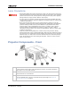
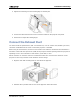
Installation and Setup D Air Filter Cover and Air Filter Located behind the air filter cover is a replaceable air filter. The air filter filters the intake air before it begins circulating in the front compartment to cool the main electronics. E Air Intake F Projector Lens See Optional Accessories on page 33 for a list of available lenses.
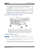
Installation and Setup Adjust Tilt and Level the Projector The front-to-back and side-to-side tilt of the projector must not exceed 15 degrees. 1. Loosen the lock nut with a 3/4 in. or 19mm wrench. 2. Turn the adjustable feet on the bottom of the projector clockwise or counter-clockwise 1/8th of a turn at a time to move the projector up or down. When adjusting two or more feet at once, always adjust them the same amount. This keeps equal weight distribution on all feet for stability. 3.
Installation and Setup 3. Tighten the mounting arm until it fits tightly on the ball joint. 4. Connect the cable from the TPC to the connector located on the projector rear panel. 5. Tilt the TPC to adjust the viewing angle. Connect the Exhaust Duct You must install the optional duct (P/N: 119-103105-xx) if an air volume of 9,000 BTU (per hour) cannot be ventilated from the room in which the projector is installed.
Installation and Setup Install the Lens The lens seals the projection head, preventing contaminants from entering the main electronics area. Do not operate the projector without a lens installed. Install a lens plug when you install or transport the projector. 1. Move the lens clamp on the front of the projector to the open position. 2. Position the lens so the lens retaining ring mounts align with the lens mount. 3. Remove the lens caps from the front and rear of the lens.
Installation and Setup 6. Move the lens clamp to the locked position. Install the Lamp This procedure should only be performed by a Christie accredited technician. High-pressure lamp may explode if improperly handled. Always wear approved protective safety clothing whenever the lamp door is open or when handling the lamp. Failure to comply results in death or serious injury. 1. If the projector is operating, turn it off and allow it to cool a minimum of 15 minutes. 2.
Installation and Setup 7. Loosen the cathode screw (D) with the 5 mm hex key attached to the lamp door. A Anode Terminal B Anode Wire C Reflector D Cathode Screw E Cathode Nut F Cathode Clamp 8. Install the lamp: Handle the lamp by the cathode/anode end shafts only, never the glass. DO NOT over-tighten. DO NOT stress the glass in any way. Check leads. Make sure the anode (+) lead between the lamp and igniter is well away from any projector metal, such as the reflector or fire wall.
Installation and Setup f. Hand-tighten the cathode nut (E). Make sure the smooth portion of the nut is against the cathode clamp. g. Tighten the cathode screw (D) with a hex key. h. Align the ring terminal on the anode wire (B) with the mounting position, ensuring the crimped side of the wire is facing out. i. Tighten the anode screw. j. Route the anode lead away from nearby metal surfaces. 9. Close the lamp access door and tighten the 2 thumbscrews. 10. Close and lock the rear access door.
Installation and Setup Item B Description • SOFTST - (Software State) Indicates the state of the software application running on the ICP. During normal operation, this LED blinks. During start up, the LED changes from off to blinking. • OSST - (Operating System State) Indicates the state of the ICP operating system. During normal operation, the LED is green. During start up, the LED changes from off to green. • FMTST - (FMT FPGA State) Indicates the state of the FMT FPGA.
Installation and Setup Item Description N Connects the projector to external input and output devices, such as the Christie ACT. O Connects the projector to non-cinema video and graphics sources. These are single-link ports for single-link cables and connectors. The connectors can be used together as a twin-link DVI port. P Connects the projector to high-definition cinema sources. The connectors can be used together to deliver Dual Link HD-SDI following the SMPTE 372M standard.
Installation and Setup PIN Positive Negative Description GPOUT #3 Pin 11 Pin 30 Reserved GPOUT #4 Pin 12 Pin 31 Output GPOUT #5 Pin 13 Pin 32 Output GPOUT #6 Pin 14 Pin 33 Output GPOUT #7 Pin 15 Pin 34 Output PROJ_GOOD Pin 16 Pin 35 Projector Good This diagram illustrates how to wire a GPIO cable to a server or a 3D device: The recommended operating point is 5mA, the maximum current is 50 mA, and the forward voltage drop is ~ 1 V (@ 5 mA).
Installation and Setup PIN 8 Signal Name Health output Direction Out Description Playback stops and the open collector registers low when one of these interlocks is activated: • Lamp Door • Lamp Blower • Extractor • Tamper • Marriage • Ballast Communication Playback functions normally when the open collector registers high and all CineLink and Lamp interlocks are not activated. 9 Ground Out Ground. All SCCI inputs require a pulse input of 50ms to several seconds to operate reliably.
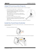
Installation and Setup 4. Insert a bare end of the protected earth wire into the hole on the top of the ground lug so it is beneath the threaded bolt. 5. Tighten the threaded bolt to 50 in-lb. 6. Connect the other bare end of the protected earth wire to the building ground. 7. Connect one end of the projector power cord to the AC receptacle on the lower-left rear corner of the projector and then connect the other end of the power cord to an AC receptacle. 8.
Installation and Setup Activate Marriage You must complete marriage to display encrypted content and to comply with the Digital Cinema Initiatives (DCI) specification. You cannot complete marriage remotely. In addition, an authorized employee must be physically present to verify that the anti-tamper seal on the firewall is unbroken, the projector is unaltered, and to press the marriage button on the card cage faceplate. 1. Log on to the projector with marriage permissions.
Installation and Setup Field Description Management IP The IP address where SNMP information and notifications are sent. Download MIB to USB Sends the SNMP Management Information Base (MIB) file to a USB flash drive. Apply Applies SNMP settings. Serial Access Grants access to serial connections. Ethernet Access Grants access to Ethernet connections. Add the Lamp Information to the Lamp History 1. If the lamp is on, tap the lamp off ( ) icon to turn it off. 2.
Installation and Setup 2. Tap Menu > Advanced Setup > LampLOC Setup. 3. Tap Display Full Screen White Test Pattern. 4. Tap Do Auto. Adjust the Image to Fit Your Screen This procedure must be completed before you complete a boresight adjustment. 1. Verify the projector is properly positioned relative to the screen. See Position the Projector on page 4. 2. Display a RGB-12bit-Full Screen White test pattern and center the image: a. Tap the Test Pattern icon ( ) in the task bar. b. Tap All Test Patterns. c.
Installation and Setup 8. Display a full white test pattern: a. On the TPC, tap the Test Pattern icon ( ) in the task bar. b. Tap All Test Patterns. c. Tap RGB-12bit-Full Screen White. 9. If the test pattern is focused and centered on the screen you do not need to complete further image adjustment. If the image is not focused and centered on the screen, complete one of these procedures: a. If the image appears distorted and resembles a trapezoid, see Correct Keytsone Effect in the CP2215 User Manual. b.
Maintenance This section provides information and procedures for performing projector maintenance. You should read through this section in its entirety before performing maintenance activities. When you perform projector maintenance, obey all warnings and precautions. Inspect Ventilation Vents and louvers in the projector covers provide ventilation, both for intake and exhaust. Never block or cover these openings. Do not install the projector near a radiator, heat register, or within an enclosure.
Maintenance Clean the Radiator Filter 1. Tap and hold the red power button on the TPC Main panel to turn the lamp and projector off. 2. Allow the lamp to cool for a minimum of 15 minutes. 3. Unplug the projector. 4. Remove the top lid. 5. Reach into the projector and then loosen the first service panel screw. 6. Open the integrator rod access door and loosen the second service panel screw. CP2215 Quick Start Guide 020-101295-01 Rev.
Maintenance 7. Push the clips on the top of the service panel down and out to remove the service panel. 8. Loosen the thumbscrew securing the radiator filter door. 9. Pull the filter up and out and then wash the radiator filter with water and a mild detergent or clean it with compressed air. 10. When the filter is completely dry, reinstall it and then install the service panel and top lid. Inspect the Lamp Always disconnect the projector from AC power and wear authorized protective safety gear.
Maintenance • For the lens only - lens cleaning solution such as Melles Griot Optics Cleaning Fluid 18LAB011 or equivalent • Cotton swabs with wooden stems. • Lens cleaning cloth or microfiber such as Melles Griot 18LAB024 or equivalent. Clean the Lens A small amount of dust or dirt on the lens has minimal effect on image quality-to avoid the risk of scratching the lens, clean the lens only if absolutely required. Remove Dust 1.
Maintenance Remove the Existing Lamp 1. Tap and hold the red power button on the TPC Main panel to turn the lamp and projector off. 2. Allow the lamp to cool for a minimum of 15 minutes. 3. Unplug the projector. 4. Put on your protective clothing and face shield. 5. Insert the key in the lock on the lamp door, turn the key, and then open the lamp door. Do not place heavy objects on the open lamp door. 6. Loosen the two thumbscrews (A and B) and open the lamp access door. 7.
Maintenance g. With the lamp removed, visually inspect the reflector and clean if necessary. A Anode Terminal B Anode Wire C Reflector D Cathode Screw E Cathode Nut F Cathode Clamp 8. Remove the new lamp from the protective case. 9. Loosen the cathode screw and remove the cathode nut from the lamp. Install the New Lamp Handle the lamp by the cathode/anode end shafts only, never the glass. DO NOT overtighten. DO NOT stress the glass in any way. Check leads.
Maintenance the reflector and guide the lamp onto the cathode clamp. Be careful not to hit the lamp against the reflector. 5. Thread on and hand-tighten the cathode nut. Make sure the smooth portion of the nut is against the cathode clamp. 6. Tighten the cathode clamp (F) with a hex key. 7. Align the ring terminal on the anode wire (B) with the mounting position ensuring the crimped side of the wire is facing out. Tighten the anode screw. Route anode lead away from nearby metal surfaces. 8.
Maintenance Inspect the Card Cage Filter Use only high efficiency Christie approved filters. Never operate the projector without the filter installed. You should check the condition of the card cage air filter monthly. Clean or replace the card cage air filter sooner if you are operating the projector in a dusty or dirty environment. The filter is located on the left side of the projector behind the air filter cover. 1. Loosen the 2 captive screws on the bottom of the filter cover. 2.
Maintenance 4. Rinse the filter thoroughly by holding it on an angle under cool running water. The air flow arrow on the side of the filter should face down. 5. Repeat steps 3 and 4 if the filter still appears dirty. 6. Shake the filter over a container until most of the water is removed. 7. Place the filter on its edge on a flat, stable surface and allow it to dry thoroughly. 8. To confirm that the filter is dry, place it over a dry paper towel and shake it.
Specifications This section provides detailed specifications for the Christie CP2215 projector. Due to continuing research, specifications are subject to change without notice. Power Requirements AC Input (A) Below 200VAC, when the lamp is ignited, a 25 A input surge current might occur for three seconds.
Specifications Lamp The ballast is power regulated and has a maximum current of 97A. Therefore the maximum power specification for a given lamp may not be achievable until the lamp has aged, since lamp voltage increases with hours of use. Projectors typically force a 10 minute cool down period. Make sure you do not re-strike the lamp any sooner than 2 minutes into this cool down period since hot re-strikes reduce lamp life. Item Type Description Xenon Short Arc Lamp CXL-14M (1.4kW) 1000W min.
Specifications Regulatory This product conforms to the following regulations related to product safety, environmental requirements and electromagnetic compatibility (EMC). Safety • CAN/CSA C22.2 No.
Specifications Environment Operating Environment Item Description Temperature 10°C to 35°C (50°F to 95°F) Humidity (non-condensing) 20% to 80% Altitude 0 - 3000 meters Maximum ambient temperature 35°C Non-Operating Environment Item Description Temperature -25°C to 65°C (-13°F to 149°F) Humidity (non-condensing) 0% to 95% CP2215 Quick Start Guide 020-101295-01 Rev.
Specifications Accessories Standard (sold with product) • Touch panel controller (TPC) with interface cable • Set up guide • Interconnect diagram • Power cord Optional Accessories Item Zoom Lenses Description/Part Number • 1.2-1.75” DLPCine Zoom (108-350109-01-XX) • 1.3-1.75” DLPCine Zoom (108-320106-XX) • 1.39-1.9” DLPCine Zoom (108-327103-XX) • 1.5-2.2” DLPCine Zoom (108-329105-XX) • 1.75-2.4” DLPCine Zoom (108-321107-XX) • 1.9-3.0” DLPCine Zoom (108-328104-XX) • 2.4-3.
*000-104025-01* ASSY TECH DOCS CP2215 Corporate offices Worldwide offices USA – Cypress ph: 714-236-8610 Australia ph: +61 (0) 7 3624 4888 Canada – Kitchener ph: 519-744-8005 Brazil ph: +55 (11) 2548 4753 Consultant offices China (Beijing) ph: +86 10 6561 0240 Italy ph: +39 (0) 2 9902 1161 China (Shanghai) ph: +86 21 6278 7708 Eastern Europe and Russian Federation ph: +36 (0) 1 47 48 100 France ph: +33 (0) 1 41 21 44 04 Germany ph: +49 2161 664540 India ph: +91 (080) 6708 9999 Singapore ph: +65