GS Series DWX555-GS/DHD555-GS/DWU555-GS USER MANUAL 020-000724-01
The CD included with this printed manual contains an electronic copy in English. Please read all instructions before using or servicing this product. Le DC fourni avec ce manuel imprimé contient une copie électronique en français. S'il vous plaît lire toutes les instructions avant d'utiliser ou de réparer ce produit. Die mit dieser gedruckten Anleitung gelieferte CD enthält eine elektronische Kopie in Deutsch. Bitte lesen Sie alle Anweisungen, bevor Sie dieses Produkt verwenden oder warten.
NOTICES COPYRIGHT AND TRADEMARKS Copyright ©2014 Christie Digital Systems USA, Inc. All rights reserved. All brand names and product names are trademarks, registered trademarks or trade names of their respective holders. REGULATORY The product has been tested and found to comply with the limits for a Class A digital device, pursuant to Part 15 of the FCC Rules. These limits are designed to provide reasonable protection against harmful interference when the product is operated in a commercial environment.
GENERAL Every effort has been made to ensure accuracy, however in some cases changes in the products or availability could occur which may not be reflected in this document. Christie reserves the right to make changes to specifications at any time without notice. Performance specifications are typical, but may vary depending on conditions beyond Christie's control such as maintenance of the product in proper working conditions.
Table of Contents 1. SAFETY 2. INTRODUCTION 2.1 2.2 2.3 2.4 2.5 Projector Components .................................................................................................. 2-1 Built-in Keypad .............................................................................................................. 2-4 Input/Output (I/O) Panel ................................................................................................ 2-5 Remote Control ...................................................
Table of Contents 5. TROUBLESHOOTING 6. SPECIFICATIONS 6.1 6.2 6.3 6.4 6.5 6.6 6.7 6.8 6.9 Inputs ............................................................................................................................ 6-1 PIP/PBP Compatibility .................................................................................................. 6-6 Key Features ................................................................................................................ 6-7 List of Components...........
Section 1: SAFETY 1. SAFETY Read through this document in its entirety and understand all warnings and precautions before attempting to operate the projector. WARNING . • • • • • • • • • • • • • • • 1-1 Do not look into the projector lens when the laser is on. The bright light may result in permanent eye damage. To reduce the risk of fire or electric shock, do not expose this projector to rain or moisture. Do not open or disassemble the projector as this may cause electric shock.
Section 1: SAFETY Warning This is a class A product. In a domestic environment this product may cause radio interference in which case the user may be required to take adequate measures. Important Laser Notice MAX OUTPUT:8.0mW WAVE LENGTH:440~455nm Complies with 21 CFR 1040.10 and 1040.11 except for deviations pursuant to Laser Notice No. 50, dated June 24, 2007. IEC 60825-1:2007 . • • • • • • • WARNING This projector is a Class 2 laser device that conforms with IEC 608251:2007 and CFR 1040.
Section 2: INTRODUCTION 2. INTRODUCTION The product specified in this document is a high brightness, high-resolution video/graphics 1-chip laser based projector. The projector is available in WXGA, HD and WUXGA resolutions. The projector utilizes Digital Light Processing (DLP®) technology from Texas Instruments. It is primarily designed for fixed installation markets. 2.1 Projector Components Front View 1 2 3 4 Ind.
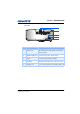
Section 2: INTRODUCTION Rear View 1 HDBaseT REMOTE IN REMOTE OUT HDMI VGA IN VGA OUT DISPLAY PORT 2 DVI MINI USB GREEN/Y BLUE/PB RED/PR RS232 USB ETHERNET CVBS S-VIDEO 3 4 5 K Ind. Part Name Description 1 Rear IR Sensor Receives signals from the IR remote. Keep the signal path unobstructed for uninterrupted communication with the projector. 2 Input/Output (I/O) Panel Connects the projector to external devices. 3 AC Input Connect to the supplied power adapter.
Section 2: INTRODUCTION Left View 1 Right View 2 3 4 Ind. 2-3 Part Name Description 1 Cooling Air Vents (Intake) Keep these vents unobstructed to prevent the projector from overheating. 2 LED Status Indicators Displays the status of the projector. They are (from left to right): LIGHT, STATUS, and PIC MUTE. 3 Built-in Keypad Controls the projector. 4 Cooling Air Vents (Exhaust) Keep these vents unobstructed to prevent the projector from overheating.
Section 2: INTRODUCTION 2.2 Built-in Keypad 1 7 2 8 3 4 9 5 10 6 11 Ind.
Section 2: INTRODUCTION 2.3 Input/Output (I/O) Panel 1 2 3 4 5 HDBaseT REMOTE IN REMOTE OUT HDMI VGA IN 6 VGA OUT 7 8 DISPLAY PORT DVI MINI USB GREEN/Y BLUE/PB RED/PR 9 Ind. 2-5 Connector Name RS232 10 USB 11 ETHERNET 12 13 Ind.
Section 2: INTRODUCTION 2.4 Remote Control 1 2 16 3 17 4 5 18 19 20 6 21 7 22 8 9 23 10 24 25 11 26 12 GS Series User Manual 020-000724-01 Rev.
Section 2: INTRODUCTION Ind. 2-7 Part Name Description 1 Picture Mute Display or blank the video image. 2 Power on Turn projector ON. 3 Gamma Adjust mid-range levels. 4 Bright Adjust amount of light in the image. 5 PIP/PBP Turn PIP/PBP ON/OFF. 6 Size Adjust the PIP/PBP size 7 Number Keys Enter a number, such as a channel, value, etc. 8 Help Display context-sensitive help. 9 Menu Display menus. 10 Arrow Keys • • 11 Test Display a test pattern.
Section 2: INTRODUCTION 2.5 LED Status Indicators The LED status indicators are located on the right side of the projector. Each LED is defined below.
Section 2: INTRODUCTION • PICTURE MUTE LED LED Status 2-9 Projector State Green (solid) Light is on - image is displayed Orange (solid) Light is on - image is blank GS Series User Manual 020-000724-01 Rev.
Section 2: INTRODUCTION GS Series User Manual 020-000724-01 Rev.
Section 3: INSTALLATION 3. INSTALLATION 3.1 Connect to Computer Laptop Desktop 9 1 2 HDBaseT REMOTE IN 3 REMOTE OUT HDMI 4 5 VGA IN 6 VGA OUT 7 DISPLAY PORT 8 DVI MINI USB GREEN/Y Ind. BLUE/PB Connector Name RED/PR RS232 Ind. USB ETHERNET CVBS Connector Name S-VIDEO Ind.
Section 3: INSTALLATION 3.2 Connect to Video Equipment Component video output equipment DVD player Video cassette recorder 3 5 1 2 7 8 4 6 HDBaseT REMOTE IN REMOTE OUT HDMI VGA IN VGA OUT DISPLAY PORT DVI MINI USB GREEN/Y Ind. Connector Name BLUE/PB RED/PR Ind. RS232 USB Connector Name 1 Component (YPbPr) Cable 4 VGA in Cable 2 HDMI Cable 5 3 RCA Component Cable 3 VGA to RBG SCART 6 15-pin to 3 RCA Component/HDTV Adapter ETHERNET CVBS Ind.
Section 3: INSTALLATION 3.3 Turn the Projector On 1. Ensure that the power cord and signal cable are securely connected. The Power button on the built in keypad is illuminated. 1 2. Turn on the projector by pressing " " on the remote control or press " " on the built-in keypad. The Status LED is Orange with a long blink. 12 3. Turn on the source. Select Input Key on the remote control to select an input source (VGA, BNC, HDMI, Component, S-Video or Composite Video). 13 4.
Section 3: INSTALLATION 3.5 Adjust the Projector Position When you select a position for the projector, consider the size and shape of your screen, the location of your power outlets, and the distance between the projector and the rest of your equipment. Follow these general guidelines: • Position the projector on a flat surface at a right angle to the screen. The projector (with the standard lens) must be at least 3 feet (0.9m) from the projection screen.
Section 3: INSTALLATION Table Top Mode - The projector is in table top mode when the viewing angle is from 0° to <60° and from >300° to 360° as illustrated below. 300~360 deg 0 deg 0~60 deg Portrait Mode - The projector is in portrait mode when the viewing angle is from 60° to 120° as illustrated below. Portrait mode 60~120 deg • Portrait mode 60~120 deg WARNING In portrait orientation, the Portrait Side Cover must be installed on the side of the projector which is now the lower side.
Section 3: INSTALLATION Non-Supported Modes - The projector is in non-portrait mode when the viewing angle is 240° to 300° as illustrated below. The "orange" status LED on projector lights on. 270~300 deg 240~270 deg 270 deg WARNING • The projector should not be operated in Non-Portrait Mode. GS Series User Manual 020-000724-01 Rev.
Section 3: INSTALLATION 3.6 Calculate Lens Offset • • The vertical image offset (shift) ranges for the projector are +/-100% (WXGA/WUXGA) and +/-120% (HD). The horizontal image offset (shift) range for the projector are +/-30% (WXGA/HD/WUXGA). The method for calculating lens offset complies with Industry standards. Example for Vertical lens offset: - At 0% offset (or on axis), the center of the image is on the lens center, so that half of the image appears above and half appears below the lens center.
Section 3: INSTALLATION Vertical Image Offset: 100% Offset (WUXGA) Image has been offset 600 pixels above lens center, so the center of the image is now 600 pixels above where the center of the image was at 0% offset (or lens center). The offset is +600/600 * 100% = +100%. 600 pixels of shift above lens center.
Section 3: INSTALLATION HD Projectors: Vertical Image Offset: 0% Offset (HD) No offset is applied - 0% offset. Half of the image appears above lens center and half of the image appears below lens center. 540 pixels above lens center. Lens center 540 pixels above lens center. Vertical Image Offset: 120% Offset (HD) Image has been offset 648 pixels above lens center, so the center of the image is now 648 pixels above where the center of the image was at 0% offset (or lens center).
Section 3: INSTALLATION Vertical Image Offset: -120% Offset (HD) Image has been offset 648 pixels below lens center, so the image has an offset of -648/ 540 * 100% = -120% Lens center 648 pixels of shift below lens center. Total of 1296 pixels (648+648) of display are below lens center. Horizontal Image Offset: +/-30% Offset 1920 pixels +192 pixels Lens center -192 pixels Image has been offset 192 pixels left or right of lens center.
Section 3: INSTALLATION WXGA Projectors: Vertical Image Offset: 0% Offset (WXGA) No offset is applied - 0% offset. Half of the image appears above lens center and half of the image appears below lens center. 400 pixels above lens center. Lens center 400 pixels above lens center. Vertical Image Offset: 100% Offset (WXGA) Image has been offset 400 pixels above lens center, so the center of the image is now 400 pixels above where the center of the image was at 0% offset (or lens center).
Section 3: INSTALLATION Vertical Image Offset: -100% Offset (WXGA) Image has been offset 400 pixels below lens center, so the image has an offset of -400/ 400 * 100% = -100% Lens center 400 pixels of shift below lens center. Total of 800 pixels (400+400) of display are below lens center. Horizontal Image Offset: +/-30% Offset 1280 pixels +128 pixels Lens center -128 pixels Image has been offset 128 pixels left or right of lens center.
Section 3: INSTALLATION 3.7 Removing and Installing the Lens When handling the projector after lens installation, make sure the front lens cap is placed on the lens to protect the lens surface from potential damage. When carrying or moving the projector, do not handle by the lens. This may damage the lens, the chassis or other mechanical parts within the projector. Installation Steps: 1. Center the lens: Ensure that the lens is at or near its center position.
Section 3: INSTALLATION 3.8 Cable Cover Installation 1. Rotate the cable cover and insert the two guide pins into the guide holes. 2. Press and hold both lower corners of the cable cover while inserting the sheet clips into the projector casing. Guide Pin Guide Hole Hold and Press Here GS Series User Manual 020-000724-01 Rev.
Section 3: INSTALLATION 3.9 Portrait Cover Installation 1. Attach the Portrait cover to the left side of the projector and secure with the 6 step screws. Tighten the six screws 2. Mount the projector in an appropriate mounting kit, using the 4 mounting points on the underside of the projector. • • 3-15 WARNING Mount with the portrait cover side facing downwards. The projector must not stand on a table top on the portrait cover GS Series User Manual 020-000724-01 Rev.
Section 3: INSTALLATION 3.10 Ceiling Mount Installation Mount the projector with an appropriate mounting kit, using the 4 mounting points on the underside of the projector. • • When not mounted properly, the projector may fall, causing hazards or injury. The warranty on this projector does not cover any damage caused by the use of any non-recommended ceiling mount kit or installation of the ceiling mount kit in an improper location.
Section 4: OPERATION 4. OPERATION The projector has multilingual On-Screen Display (OSD) menus that allow you to make image adjustments and change a variety of settings. • • • • • 4-1 Most of the projector controls are accessed from within the projector menu system. There are several groups of related functions, with each group selectable from the Main menu as shown below. Press the MENU button on the remote control or on the built-in keypad on the rear of the projector to display the main menu.
Section 4: OPERATION 4.1 Size and Position Menu Size Presets Display an image with the detected size, or resize the image by maximizing either the height, width or both, or resize to the maximum size possible while keeping the original aspect ratio. • Auto: Display with the detected size. • Native: Display in its native resolution. • 4:3: Retain 4:3 aspect ratio. • Letterbox: Display with the black borders on the top and bottom. • Full Size: Fill the screen (regardless of the source).
Section 4: OPERATION Pixel Phase Analog RGB Signals only. Adjust pixel phase when the image still shows shimmer or noise after pixel tracking is optimized. Pixel phase can adjust the phase of the pixel-sampling clock relative to the incoming signal. Horz Position Move the image right or left within the area of available pixels. Vert Position Move the image up or down within the area of available pixels. Digital Horz Zoom Change the size of projector's display area horizontally.
Section 4: OPERATION • • Off: No Geometric correction is applied to the image. Horz Keystone: Adjust the keystone horizontally and make a more square image. Horizontal keystone is used to correct a keystoned image shape in which the left and right borders of the image are unequal in length, and the top and bottom are slanted to one of the sides. This is intended for use with horizontally on-axis applications.
Section 4: OPERATION • Pincushion/Barrel: Allow for correction for slight curved distortion from the lens or projection surface. Ind. A B • C D WXGA 1080P WUXGA 8.38% 8.35% 8.37% 4.59% B 3.5% 3.98% C 6.4% 6.4% 6.5% D 6.4% 6.4% 6.5% 4-Corner: Allow the image to be squeezed to fit an area defined by moving each of the four corners' x and y position. A A B B Ind. WXGA 1080P WUXGA B A 10.0% 8.4% 8.3% B 9.5% 7.9% 7.
Section 4: OPERATION Auto Image Force the projector to reacquire and lock to the input signal. This is useful when signal quality is marginal. "Normal mode" can support all of the 4:3 input sources. "Wide mode" can support all of the 16:9 input source & most of the 4:3 input source. For those 4:3 input sources not recognized by "Wide mode" (example 1400 x 1050), perform Auto Image using "normal mode". GS Series User Manual 020-000724-01 Rev.
Section 4: OPERATION 4.2 Image Settings Menu Brightness Adjust the intensity of the image. Contrast Adjust the degree of difference between the lightest and darkest parts of the picture and change the amount of black and white in the image. Color Space Select a color space that has been specifically tuned for the input signal. Useful only for analog signals and certain digital sources. Detail Select the edge clarity of the image. Video Options This function is used with video sources only.
Section 4: OPERATION • • • • Video Black Level: Analyze the current input image and calculate an offset value which is then added to the analog to digital converter black level value. This ensures optimum black level for each analog source. Detect Film: Control film mode detection and determine whether the original source of the input video was film or video. Closed Captions: Control closed caption display while audio is not muted.
Section 4: OPERATION • • • 4-9 White Peaking: (video source only) Increase the brightness of whites that are near 100%. Color Temperature: Change the intensity of the colors. Select a listed relative warmth value. Edge Enhancement: Apply the edge enhancement process. GS Series User Manual 020-000724-01 Rev.
Section 4: OPERATION 4.3 Configuration Menu Language Allows you to select an available language for the OSD display, from English, French, German, Italian, Spanish, Chinese(simplified), Japanese, Korean, and Russian. Lens Settings • • • • Focus and Zoom: Adjust the focus and zoom the image in or out. Lens Shift: Shift the lens up and down or left and right. Lock Lens Motors: Select this function to prevent all lens motors from moving.
Section 4: OPERATION Menu Preferences • • • • Menu Horz Position: Change the horizontal position of the OSD. Menu Vert Position: Change the vertical position of the OSD. Show Messages: Display status messages on the screen. Menu Transparency: Change OSD menu background to be transparent. NOTE: • • • As the value increases, more of the image behind the menu is visible. Splash Screen: Choose which splash screen is to be used.
Section 4: OPERATION • • • Serial Port Echo: Control whether the serial port echoes characters. Serial Port Path: Select the serial port path from either RS232 or HDBaseT. Projector Address: Set the projector address (0-9). The projector will respond to IR remotes set either at the same address as the projector or to IR remotes set to address 0. Image Blending Adjust blend widths and settings to left, right, top and/or bottom sides to create a seamless multi-projector stitched image.
Section 4: OPERATION Color Matching You may require a unique color gamut (range) for a single projector or application, or you may need to precisely match colors across multiple adjacent displays. Use Color Matching by Meter Adjustment or by Manual Adjustment to define the precise hue of each primary color component (red, green, blue and white). The x/y coordinates for each color define its location on the standard CIE chromaticity graph.
Section 4: OPERATION • Manual Adjustment 1 Adjust color slide bars and judge image color by eye or meter. A userdefined color "adjustment" can be applied. 2 Use this submenu if you do not have specific color coordinates in mind and will judge color performance by eye or meter. As for Meter Adjustment, each color control actually defines new x/y coordinates for that color and changes its hue.
Section 4: OPERATION 4.4 Light Source Light Source Mode Select Constant Power, Constant Intensity or ECO mode. When in ECO mode, the projector will adjust to the lowest fan speed and switch the laser diode power to the minimum setting. Constant Power Set the value of the laser diode power (in Watts). Constant Intensity Set the value for the Constant Intensity to maintain constant brightness.
Section 4: OPERATION 4.5 Status Menu The read-only Status menu lists a variety of details about the standard and optional components currently detected in the projector. For DHD Models GS Series User Manual 020-000724-01 Rev.
Section 4: OPERATION For DWU Models 4-17 GS Series User Manual 020-000724-01 Rev.
Section 4: OPERATION For DWX Models GS Series User Manual 020-000724-01 Rev.
Section 4: OPERATION 4.6 Input Switching & PIP Menu Main Input From the list of active inputs, select one to be used as the main image. PIP/PBP Input From the list of active inputs, select one to be used as the PIP/PBP. PIP/PBP Enable Toggle between displaying two sources at once (Main and PIP/PBP images) or one source only. The check box turns the PIP/PBP source ON and OFF. Refer to Section 6.2 for the Main and PIP/PBP compatibility table.
Section 4: OPERATION NOTE: PIP/PBP layout and size table as described below. P : indicates primary source region (lighter color). * : Both source regions are the same size.
Section 4: OPERATION Input Key Use it to list all of the sources or change the sources. Blank on Signal Switch When the function is enabled, the projector will blank the screen before timing is stable when change source. 4.7 Language Menu Allows you to select an available language for the OSD display. 4.8 Test Pattern Menu Choose the desired internal test pattern to display, or select OFF to turn off a test pattern.
Section 4: OPERATION 4.9 Web User Interface 4.9.1 Logging On Open your web browser and type the IP address (in the address bar) assigned to your projector. 1 Select the log in level from the Access type drop-down list 2 Enter the Password in the Password field 3 Select the appropriate language from the Language drop-down list. 4 Click the Press login button. The Main window appears. 4.9.2 Main Tabbed Page - General GS Series User Manual 020-000724-01 Rev.
Section 4: OPERATION • • • Control Panel Select main source / PIP source, enable/disable PIP/PBP, change the layout / PIP size, swap, and change the test pattern. Projector Information Panel Check the projector information for power status, Pic mute status, OSD status, IP address and Mac address. Switch Panel Switch the on/off status of power, Pic mute, and OSD. 4.9.
Section 4: OPERATION 4.9.4 Main Tabbed Page - Lens Control the focus, lens shift and zoom adjustments for the lens. GS Series User Manual 020-000724-01 Rev.
Section 4: OPERATION 4.9.5 4-25 Network GS Series User Manual 020-000724-01 Rev.
Section 4: OPERATION • • • • Restart Network Execute a Network restart. This will not change any of the network settings. Network Factory Reset Execute a network factory reset. Network settings will be reset to the following default values: - Projector Name = Christie@ + Serial Number - Show Network Messages = ON - LAN Settings: - Manual - IP Address = 192.168.0.100 - Subnet Mask = 255.255.255.0 - Default Gateway = 192.168.0.100 - WLAN Settings: - Enabled - Start IP = 192.168.1.100 - End IP = 192.168.1.
Section 4: OPERATION - • • • 4-27 Enter the IP address range, netmask and default gateway for the wireless LAN. SNMP Panel - The SNMP (Simple Network Management Protocol) interface provides network administrators with a common way to manage their network devices from a single remote location. SNMP allows an administrator to query a number of devices to see their current status/ configuration.
Section 4: OPERATION 4.9.6 Tools To Use the Tools tabbed pages to control "Size & Position", "Image Settings", "Configuration", "Light Source", "Input Switching & PIP" and "Test Pattern. 4.9.7 Administrator Page Add or delete a user or change password GS Series User Manual 020-000724-01 Rev.
Section 4: OPERATION 4.9.8 • • 4-29 About Page Version Tab View the main firmware version, network firmware version, projector model name, and projector serial number. License Tab The license information of the computer program is displayed. GS Series User Manual 020-000724-01 Rev.
Section 4: OPERATION 4.10 Christie Presenter The Christie Presenter application allows a remote desktop from a host PC to be displayed on the network display through Ethernet, USB, or wireless transports. It can adapt to different network settings (DHCP, fixed IP, and direct link by USB/Ethernet cable). Christie Presenter can be downloaded from the Christie website or from the web page of the projector. 4.10.1 Connect to the Projector 1.
Section 4: OPERATION Power on the Projector. Obtain the WiFi SSID from the OSD menu Main Menu > Configuration > Communications > WLAN Connect your PC device to the wireless SSID for the selected projector . Example: "Christie@0111000123". 4.10.2 Install Christie Presenter software 1. Use a web browser to connect to the projector's network address (Default address 192.168.1.100) 2. Download and install the Christie Presenter Software 4-31 GS Series User Manual 020-000724-01 Rev.
Section 4: OPERATION 3. Configure the Christie Presenter Software. The name entered is used to identify all computers connected to the projector via the Christie Presenter software via either wired or wireless connections. The Network Display Management -> Device Management tab will show all current connections. 4.10.3 Use Christie Presenter 1. Press the autorun icon in the system tray to pause or play the USB display. GS Series User Manual 020-000724-01 Rev.
Section 4: OPERATION 2. After starting the Christie Presenter application, the main window can been seen (shown below). Icon Description Connect and search network display Stop/start displaying desktop contents to connected network display Select display region Configure Christie Presenter Manage all connected network displays Disconnect all connections Connect and search network display 1 4-33 Click the button to enter into the connection menu section. GS Series User Manual 020-000724-01 Rev.
Section 4: OPERATION 2 If the IP address of the projector is known, enter the IP address and click the "Connect" button. If the IP address is not known, click the "Search" button to search for the projector on the network and select the projector to which you want to connect. Select the option "Directly" in order to proceed to the log in interface. 3 Input "User type" and "Password" in the log-in interface. Select the display port (the default is full screen).
Section 4: OPERATION Select display region Once the connection is set up, click the button to select the size of the projection region: FullScreen, FixedSize, or Alterable. • • • 4-35 FullScreen: The default capture mode turns to Full screen when the program is launched. At that time, if screen capture starts, the image of the whole screen is transferred to a remote network display. FixedSize: FixedSize mode allows the users to place a frame on the desktop.
Section 4: OPERATION Configure Christie Presenter Click the button to configure Christie Presenter for Basic Setting and Advanced Setting. • • Basic Setting: Select language, change the region size of fixed size capture mode, and select if notification message popup is allowed. Advanced Setting: Select the quality of JPEG image, YUV sample format and network port setting. (The "Fixed" port is Port 5900) GS Series User Manual 020-000724-01 Rev.
Section 4: OPERATION Manage all connected network displays Click the button to control all the users and all the projectors connector to the same projector. con Icon Description Administrator log in. Normal user log in. Device is connected. Device is not connected. The icon shows the current status and display position of the local screen on the network display. Click on the icon to change the display position. A dialog box will appear. Click this unlock icon to change the password.
Section 4: OPERATION 4.11 Card Reader Operation There are four operation modes in the Card Reader application: - USB Flash Devices Detection Screen - Thumbnail Display Mode - Images Display Mode - Images Slide Show Mode 1. USB Flash Device Detection Screen: In this mode, the Card Reader application detects any USB flash devices hot-plug events and displays the flash device icon. When the flash device is removed from USB, the icon disappears.
Section 4: OPERATION • • • • • • • • • • • The user interface is designed to operate the card reader application with a few keys (Enter/Left/Right/Up/Down). The following buttons are supported in the user interface: Previous: Move the selected item left. (Go to previous page when this is the leftmost item) Next: Move the selected item right. (Go to next page when this is the rightmost item.) Display: Display the selected image or display the selected folder. Thumbnail: Enter the Thumbnail Display Mode.
Section 4: OPERATION • • • • • • • • The following operations are supported in the operation UI. Display: Enter the Image Display Mode. Thumbnail: Enter the Thumbnail Display Mode. SlideShow: Enter the Slide Show Mode. Actual Size: Display in actual size of the image. Best Fit: Display the image in best fit to the screen. EXIFDisp OFF/On: Enable/Disable EXIF information display. +90deg: Rotate 90 degree. -90deg: Rotate -90 degree. 4.
Section 4: OPERATION When the image can NOT be displayed due to memory limitation or can NOT support image format, the specific image is displayed on the center of the screen. 4-41 GS Series User Manual 020-000724-01 Rev.
Section 4: OPERATION GS Series User Manual 020-000724-01 Rev.
Section 5: TROUBLESHOOTING 5. TROUBLESHOOTING If you are unable to resolve an issue using the information provided in this section, contact your reseller or service center. Problem - • Solution No image appears on-screen Make sure all the cables and power connections are correctly and securely connected See "Installation". - Check if the Light Status LED is in Green. - Make sure you have removed the lens cap and the projector is switched ON.
Section 5: TROUBLESHOOTING Problem - Solution Partial, scrolling or incorrectly displayed image If you are using a Notebook: 1. Adjust resolution of the computer. 2. Press the keys listed below for your notebook manufacturer to send signal out from notebook to projector.
Section 5: TROUBLESHOOTING Problem • • • 5-3 Image is out of focus The image is stretched when displaying 16:9 DVD title Solution - Make sure both lens caps (front and back) are removed. - Adjust lens focus to fit. - Make sure the projection screen is between the required distance. - When you play anamorphic DVD or 16:9 DVD, the projector will show the best image when the projector display mode is set to 16:9 in the OSD.
Section 5: TROUBLESHOOTING GS Series User Manual 020-000724-01 Rev.
Section 6: SPECIFICATIONS 6. SPECIFICATIONS 6.
Section 6: SPECIFICATIONS Signal Type PC Resolution Frame Rate (Hz) HDMI 960x600 85 ● 1024x768 60 1024x768 VGA DisplayPort DVI ● ● ● ● 75 ● ● ● ● 1024x768 85 ● ● ● ● 1064x600 50 ● 1064x600 60 ● 1064x600 75 ● ● 1064x600 85 ● ● 1152x720 50 ● 1152x720 60 ● 1152x720 75 ● 1152x720 85 ● 1152x864 60 ● ● ● 1152x864 70 ● ● ● 1152x864 75 ● ● ● 1152x864 85 ● ● ● 1280x720 50 ● 1280x720 60 ● ● ● ● 1280x720 75 ● ● ● ● 1280x720 85
Section 6: SPECIFICATIONS Signal Type PC 6-3 Resolution Frame Rate (Hz) HDMI VGA 1280x960 60 ● ● ● 1280x960 75 ● ● ● 1280x960 85 ● ● ● 1280x1024 50 ● 1280x1024 60 ● ● ● ● 1280x1024 75 ● ● ● ● 1280x1024 85 ● ● ● ● 1360x768 50 ● 1360x768 60 ● 1360x768 75 ● 1360x768 85 ● 1366x768 60 ● ● ● ● 1400x900 60 ● ● ● ● 1400x1050 50 ● 1400x1050 60 ● ● 1400x1050 75 ● ● ● 1440x900 60 ● ● ● 1440x900 75 ● 1600x900 60 ● 1600x1200 50
Section 6: SPECIFICATIONS Signal Type PC NTSC PAL SECAM Resolution Frame Rate (Hz) HDMI 1728x1080 60 ● 1864x1050 50 ● 1864x1050 60 ● 1920X1080 50 ● 1920X1080 60 ● ● 1920X1200RB 60 ● ● ● ● 1920X1200RB 50 ● ● ● ● NTSC (M, 4.
Section 6: SPECIFICATIONS Signal Type Resolution Frame Rate (Hz) HDMI VGA 1080i 25 ● 1080i 29 1080i DisplayPort DVI Component ● ● ● ● ● ● ● 30 ● ● ● ● 720p 50 ● ● ● ● 720p 59 ● ● ● ● 720p 60 ● ● ● ● 1080s 23 ● ● 1080s 24 ● ● 1080p 23 ● ● ● ● 1080p 24 ● ● ● ● 1080p 25 ● ● ● ● 1080p 29 ● ● ● ● 1080p 30 ● ● ● ● 1080p 50 ● ● ● ● 1080p 59 ● ● ● ● 1080p 60 ● ● ● ● S- video CVBS HDTV 6-5 GS Series User Manual 0
Section 6: SPECIFICATIONS 6.
Section 6: SPECIFICATIONS 6.3 Key Features • • WXGA 0.65" 1280 x 800 or HD 0.65" 1920 × 1080 resolution or WUXGA 0.67" 1920 × 1200 resolution Projection lens compatibility: - Horizontal offset ranges: +/-30% - Vertical offset ranges: +/-100% (WUXGA/WXGA) and +/-120% (HD) NOTE: • • • • • • • • 6-7 Measurements are based on industry standards where offset is calculated as a ratio of the number of pixels shifted up/ down to half the image size.
Section 6: SPECIFICATIONS 6.4 List of Components This projector comes with all the items shown below. Check to make sure your package is complete. Contact your dealer if anything is missing. • • • • IR remote control 003-004468-01 Power cord x 4 - UK/Korea/Russia - North America - Europe - Japan DVI to HDMI dongle User manual (CD) NOTE: 6.5 Due to the difference in applications for each country, some regions may have different accessories.
Section 6: SPECIFICATIONS 6.6 REGULATORY • • Safety - CSA C22.2 No. 60950-1 - UL 60950-1 - IEC 60950-1 - EN 60950-1 Electro-Magnetic Compatibility Emissions - FCC CFR47, Part 15, Subpart B/ANSI C63.
Section 6: SPECIFICATIONS 6.7 Federal Communications Commission (FCC) Warning WARNING A shielded-type power cord is required in order to meet FCC emission limits and also to prevent interference to the nearby radio and television reception. It is essential that only the supplied power cord be used. • Use only shielded signal cables to connect I/O devices to this equipment. • GS Series User Manual 020-000724-01 Rev.
Section 6: SPECIFICATIONS 6.
Section 6: SPECIFICATIONS Level 1 Level 2 Level 3(Or List) Curve Level 4(Or List) 4-Corner Rotation Level 5(Or List) Level 6(Or List) Default Bottom Left Horz adjust. 0-140 0 Bottom Left Vert adjust. 0-80 0 Bottom Right Horz adjust. 0-140 0 Bottom Right Vert adjust. 0-80 0 0-16 Top Left Horz adjust. Size & Position Geometry Correction Rotate 4-Corner 8 0-140 0 Top Left Vert adjust. 0-80 0 Top Right Horz adjust. 0-140 0 Top Right Vert adjust.
Section 6: SPECIFICATIONS Level 1 Level 2 Level 3(Or List) Level 4(Or List) Level 5(Or List) Level 6(Or List) Default Presentation Video Picture Settings Bright By source set Real DICOM SIM User Save to User Image Freeze Off / On Off Video Film Gamma Bright By source set CRT Image settings DICOM White Peaking 0 - 100 By source set Warmest Advanced Image Settings Color Temperature Warm Cool By source set Bright Off Edge Enhancement Normal Off Maximum Off Color Enhancement CE 1
Section 6: SPECIFICATIONS Level 1 Level 2 Level 3(Or List) Level 4(Or List) 0.
Section 6: SPECIFICATIONS Level 1 Level 2 Level 3(Or List) Level 4(Or List) Level 5(Or List) TOP 0… ½ Output Height(Pixel) 0 Bottom 0… ½ Output Height 0 Left 0… ½ Output Width 0 Right 0… ½ Output Width 0 Blending Area offset 0-2000 1000 non-Blending Area Offset 0-2000 1000 Overlap Image Blending Bright Adj. Drop Off Curve 70-300 Image Gamma 1.8/2.0/2.2/2.4/2.6 2.
Section 6: SPECIFICATIONS Level 1 Level 2 Color Matching Level 3(Or List) Manual Adjustment Level 4(Or List) Level 5(Or List) Red Part of White 0 - 1000 Level 6(Or List) Default 1000 Green Part of White 0 - 1000 1000 Blue Part of White 0 - 1000 1000 Reset to Default Yes/No Blank Screen Aspect Ratio Hot-Key settings Freeze Screen Projector Info Overscan Closed Captions Model Name Serial Number Native Resolution Firmware Projector Info Configuration Boot Code Standby Mode Lens Lock Settin
Section 6: SPECIFICATIONS Level 1 Level 2 Level 3(Or List) Light Source Mode Constant Power/ Constant Intensity/Eco mode Level 4(Or List) Constant Power Constant Power 243 - 405 243, 259, 275, 292, 308, 324, 340, 356, 373, 389, 405 Constant Intensity 0 - 10 7 Light Source Level 5(Or List) Level 6(Or List) Default Total Projector Hours Light Sensor Light Sensor Calibration Calibrated? (display Yes/No) Model Name Serial Number Native Resolution Firmware Vxx, Ayy, Bzz Main Input Main Sign
Section 6: SPECIFICATIONS Level 1 Level 2 Level 3(Or List) Main Input SPEC define PIP/PBP Input SPEC define PIP/PBP Enable Level 4(Or List) OFF Level 5(Or List) Level 6(Or List) Default OFF ON Swap Size (Small/Medium/ Large) Main Layout (PBP, Main Left / PBP, Main Top / PBP, Main Right / PBP, Main Bottom / PIP-Bottom Right / PIP-Bottom Left / PIP-Top Left / PIP-Top Right) Timing Detection Mode Normal Wide Wide Active Source Signal Format Aspect Ratio Resolution Vert Refresh Horz Refres
Section 6: SPECIFICATIONS 6.9 Preset Mode tables Orion-Laser projector Descrption Bright Presentation Video Dicom PW 2X 2X 2X 2X Real 2X CW 2X 2X 2X 2X 2X Syt. mode number 0 6 6 6 6 color temperature Warm Bright Warm Warm Warm Bright Warm Please see below table for DWU/DHD & DWX Warmest Cool Gamma Video Video Video Dicom FILM White peaking 100 100 100 100 100 Mode NO.
Section 6: SPECIFICATIONS SIGNAL Composite S-video VGA/PC HDMI/DVI/ HDBaseT Default Mode Video Mode Video Mode IMAGE PAL PAL Presenta- PC Sigtion Mode nal Presenta- PC Sigtion Mode nal GS Series User Manual 020-000724-01 Rev.
Corporate offices Worldwide offices USA – Cypress ph: 714-236-8610 Australia ph: +61 (0) 7 3624 4888 Canada – Kitchener ph: 519-744-8005 Brazil ph: +55 (11) 2548 4753 Consultant offices China (Beijing) ph: +86 10 6561 0240 Italy ph: +39 (0) 2 9902 1161 China (Shanghai) ph: +86 21 6278 7708 Eastern Europe and Russian Federation ph: +36 (0) 1 47 48 100 France ph: +33 (0) 1 41 21 44 04 Germany ph: +49 2161 664540 India ph: +91 (080) 6708 9999 Singapore ph: +65 6877-8737 Japan (Tokyo) ph: 81 3 3599