J Series 2.0, 2.4, and 3.
J Series 2.0, 2.4, and 3.
NOTICES COPYRIGHT AND TRADEMARKS Copyright © 2014 Christie Digital Systems USA, Inc. All rights reserved. All brand names and product names are trademarks, registered trademarks or trade names of their respective holders. REGULATORY The product has been tested and found to comply with the limits for a Class A digital device, pursuant to Part 15 of the FCC Rules. These limits are designed to provide reasonable protection against harmful interference when the product is operated in a commercial environment.
Table of Contents 1: Introduction 1.1 Purchase Record and Service Contacts .......................................................................................1-1 1.1.1 List of Components..............................................................................................................1-1 1.2 Safety Warnings and Guidelines .................................................................................................1-2 1.2.1 General Precautions .............................................
Table of Contents 4.2.1 Lamp Does Not Ignite..........................................................................................................4-1 4.2.2 Lamp Suddenly Turns OFF..................................................................................................4-2 4.2.3 Flicker, Shadows Or Dimness..............................................................................................4-2 4.3 Blank LCD Screen, No Menu Display .........................................................
1 Introduction Every effort has been made to ensure the information in this document is accurate and reliable; however, due to constant research the information in this document is subject to change without notice. 1.1 Purchase Record and Service Contacts Whether the projector is under warranty or the warranty has expired, Christie highly trained and extensive factory and dealer service network is always available to quickly diagnose and correct projector malfunctions.
Section 1: Introduction 1.2 Safety Warnings and Guidelines 1.2.1 General Precautions HIGH BRIGHTNESS. Never look directly into the projector lens. The extreme high brightness can cause permanent eye damage. Always power down the projector and disconnect all power sources before servicing or cleaning. FIRE HAZARD. Keep hands, clothes and all combustible material away from the concentrated light beam of the projector.
Section 1: Introduction 1.2.2 AC/Power Precautions Use only the AC power cord supplied. Do not attempt operation if the AC supply and cord are not within the specified voltage and power range. See the license label on the back of the projector or Section 5 Specifications for rated voltage and power. The projector is equipped with a 3-wire plug with a grounding pin. This is a safety feature. If you are unable to insert the plug into the outlet, contact an electrician to have the outlet replaced.
2 Installation and Setup This section explains how to install, connect and optimize the projector for delivery of superior image quality. Illustrations are graphical representations only and are provided to enhance the understanding of the written material. 2.1 Projector Quick Setup and Installation The following instructions are for those preferring a quick setup. Refer to the remaining subsections for detailed setup instructions.
Section 2: Installation and Setup 2. Align the lens interface plate with the lens mount. Align the lens electrical connector with the mating connector on the lens mount. Fully insert the assembly straight into the lens mount opening without turning. Press using your hand as shown. NOTE: When installing the lens, ensure that the lens is not inserted at an angle, as this can cause damage. 3.
Section 2: Installation and Setup 2.1.2 Position the Projector 2 people are required to safely lift and install the projector. Place the projector on a sturdy, level surface and position it so that it is perpendicular to the screen at a suitable distance. The further back the projector is positioned for the screen, the larger the image will be. To level the projector adjust the 3 feet. With the projector positioned perpendicular to the screen the image will appear rectangular instead of keystoned. 2.1.
Section 2: Installation and Setup For 1900W and 2400W Models: 1. Connect the line cord of the projector to the AC receptacle at the AC inlet of the projector, then push the wire clip over the plug to retain it, as shown. For 3000W Model: 1. Remove the locking pin from the bracket surrounding the AC receptacle at the AC inlet of the projector by pressing down on the button on the end of the locking pin, and then pull upwards on the pin to remove it. 2.
Section 2: Installation and Setup 2.1.5 Power up After the AC Power has been switched on, the LCD display above the keypad indicates “Please wait” and the 4 LED status indicators at the rear of the projector will be solid amber.
Section 2: Installation and Setup There are several methods for mounting the projector. Depending on your chosen installation, one method may be more suitable than another. In typical front and rear screen installations the projector can be mounted to a secure and level surface, such as a table or cart. Carts are useful when the projector has to be moved during a presentation or from site to site.
Section 2: Installation and Setup Folded Optics In rear screen applications where space behind the projector is limited, a mirror may be used to fold the optical path. The position of the projector and mirror must be accurately set - if considering this type of installation call your dealer for assistance. 2.2.
Section 2: Installation and Setup 4. Loosen the 3 locking setscrews on the lens mount, see Figure 2-2 Screw Locations. NOTE: The setscrews must be backed out several turns to avoid contact with the inner lens mount plate. FIGURE 2-1 CROSS-HAIR PATTERN FIGURE 2-2 SCREW LOCATIONS 5. Fine tune the focus of cross-hair pattern I by adjusting the appropriate capscrew, see Figure 2-2 Screw Locations. Adjust until the cross-hair image is in focus with minimal flare. 6.
Section 2: Installation and Setup 2.2.4 Powering Down The projector can be powered down by using one of the following methods: Remote Keypad/Built-In Keypad • Press and hold POWER -OR• Press POWER twice -OR• Press POWER once, then press the DOWN key. NOTES: 1) For Step 2 and 3, if the second key is not pressed immediately, a confirmation window will appear. The second key press must be pressed within 1 second of the window appearing.
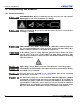
Section 2: Installation and Setup 2.3 Projector Communications 2.3.1 Status LEDs Looking from the back of the projector, the LEDs represent, from left to right; Lamp, Communications, Status, and Shutter.
3 Operation This section describes the controls and switches used for basic projector operation once it is properly installed, aligned and configured by a Christie accredited service technician. See the Safety Warnings and Guidelines in 1.2 Safety Warnings and Guidelines. 3.
Section 3: Operation 3.1.2 Remote Keypad FIGURE 3-1 REMOTE KEYPAD 3-2 J Series 2.0, 2.4, and 3.0 kW Setup Guide 020-100751-03 Rev.
Section 3: Operation 3.1.3 Wired Remote You can convert the remote keypad into a wired remote keypad using the cable provided with the projector. Connect one end into the remote and the other to the XLR connector on the input panel labeled as wired keypad. The wired remote is recommended when: • The built-in keypad is inaccessible • The lighting conditions are unsuitable for proper IR transmission NOTE: Leave the batteries in the wired remote for the laser pointer key to work. 3.1.
Section 3: Operation 3.1.
Section 3: Operation Auto Initiates an automated process in which the projector optimizes critical display parameters such as size, position, pixel tracking, etc., for the current source. These parameters are listed in the following table. An auto setup can save time in perfecting a display and you can modify the adjustments as desired. NOTE: You must have an unlocked channel present to use Auto Setup. Table 3.
Section 3: Operation Contrast Changes the level of peak white in your images. Use LEFT/RIGHT ARROW KEY until you reach the desired level of contrast—for best results, start low and increase so that whites remain bright but are not distorted or tinted and that light areas do not become fully white (i.e., “crushed”). Conversely, low contrast causes dim images. Bright Increases or decreases the black level in the image. Use LEFT/RIGHT ARROW KEY until you reach the desired level of brightness.
Section 3: Operation Shutter Press and hold SHUTTER for two seconds to toggle the internal mechanical shutter blade closed or open with a single keystroke. Or press and release SHUTTER followed immediately by UP ARROW KEY (closed) or DOWN ARROW KEY (open) to guarantee the correct state (useful if you are unsure of the present state). Alternatively, press SHUTTER, SHUTTER to toggle from the present on/off state. A closed shutter blanks the display (turns it to black).
Section 3: Operation Exit Press EXIT to return to the previous level, such as the previous menu. NOTE: EXIT does not save changes within text editing boxes (including number editing of a slide bar value) or within pull-down lists. In these cases, EXIT acts as a “cancel”. Arrow Keys Use the LEFT/RIGHT ARROW KEY to change a slide bar value or to select a different option within a pull-down list without having to first scroll through options or navigate within a menu, pull-down list or text box.
Section 3: Operation With a function menu displayed, enter a menu option number for any numbered option, or use the UP/DOWN ARROW KEY to highlight the desired option and then press ENTER. Long menus have a scroll bar on the right; use the arrow keys to access the remainder of the menu. Locked items or items that do not pertain to the current action or condition appear dimmed and cannot be selected. When finished with a function menu: • Press EXIT to return to the previous screen.
Section 3: Operation Slide Bars In Menus: The current value for a given parameter, White Uniformity such as size or vertical stretch, appears to the left of its slide bar 1. Left Side 35.6 icon (adjustment window). This number often expresses a percentage, or it may have units associated with it (such as pixels), depending on the specific option. Press LEFT/RIGHT ARROW KEY to gradually adjust the setting up or down; both the number and the length of the bar change accordingly.
Section 3: Operation 3.2.6 Edit Text Activate the Edit Window: To enter or edit text, highlight the desired parameter (such as a channel name) and press ENTER to activate its adjacent edit window. Any previously entered text is displayed with its first character highlighted in a square cursor, signifying that this character is ready for editing. Navigate Within the Edit Window: Press RIGHT ARROW KEY to move the cursor forward or LEFT ARROW KEY to move the cursor backwards as desired.
Section 3: Operation 3.3 Alarm Conditions An alarm condition consists of a message that is on the LCD display located beside the built-in keypad. There are two types of alarm conditions: • Warning Alarm • Critical Alarm A warning alarm is shown when an error or a non-optimal condition has occurred. That will generally not prevent the projector from operating. An example is when a temperature is slightly elevated.
4 Troubleshooting If the projector is not operating properly, note the symptoms and use this section as a guide to resolve the problem. If the problem cannot be resolved. contact your dealer for assistance. NOTE: A Christie accredited service technician is required when opening an enclosure to diagnose any “probable cause”. 4.1 Projector Does Not Power ON 1. Ensure projector is plugged in: Check power switch above power cord is in the ON position. 2.
Section 4: Troubleshooting 4.2.2 Lamp Suddenly Turns OFF 1. Check lamp power through the remote keypad checking the Lamp menu or from the web user interface Advanced: Lamp menu. Try increasing lamp power. 2. Check for an alarm condition on the LCD keypad display. 3. Replace the lamp. 4.2.3 Flicker, Shadows Or Dimness 1. Check lamp power through the remote keypad checking the Lamp menu or from the web user interface Advanced: Lamp menu. Try increasing lamp power. 2. Replace the lamp. 4.
Section 4: Troubleshooting 4.6 Can Not Establish Communication with Projector 1. Ensure any address changes have been saved, and reboot to implement. If you still have trouble establishing communications with a projector added to an existing Ethernet network, the projector IP address is likely in conflict with another address already in use. Contact your network administrator. 2. Ensure Ethernet settings are valid for the site. All devices should have the same subnet mask yet unique IP addresses. 4.
Section 4: Troubleshooting 4.7.5 The Display is Faint 1. Brightness and/or contrast and/or gamma may be set incorrectly. 2. The source may be double terminated. Ensure the source is terminated only once. 3. The source (if non-video) may need a different sync tip clamp location. 4.7.6 The Upper Portion of the Display is Waving, Tearing or Jittering This can occur with video or VCR sources. Check your source. 4.7.
Section 4: Troubleshooting 4.7.14Display is “Noisy” 1. Display adjustment at the input source may be required. Adjust pixel tracking, phase and filter. Noise is particularly common on YPbPr signals from a DVD player. 2. Ensure the video input is terminated (75 ohms). If it is the last connection in a loop-through chain, the video input should be terminated at the last source input only. 3. The input signal and/or signal cables carrying the input signal may be of poor quality. 4.
5 Specifications This section provides detailed J Series features; including inputs, lamp, and power requirements. NOTE: Due to continuing research, detailed features are subject to change without notice. 5.1 Feature Set 5.1.1 Air Filters (Optional) Filter media types Dust filter Fog filter Filter access Service-interchangeable via access panel 5.1.2 Lamp Ushio Xenon bubble lamp system Lamps are accessed from the rear of the projector 5.1.
Section 5: Specifications 5.2 Power Requirements High leakage current. Earth connection essential before connecting supply.
Section 5: Specifications 5.4 Accessories and Service Components PRODUCT NAME PART NUMBER SOLD WITH PRODUCT SOLD SEPARATELY Analog Input 108-309101-XX Dual Link DVI Input 108-312101-XX Video Decoder Input 108-310101-XX Dual 3G/HD/SD-SDI Input Card 108-313101-XX Twin HDMI Input 108-311101-XX DMX512 Interface 108-314101-XX TDPIC Card 108-451101-XX Dust Filter (5-pack) 132-116109-XX Fog Filter (5-pack) 132-117100-XX Lens ILS 0.
Corporate offices Worldwide offices USA – Cypress ph: 714-236-8610 Australia ph: +61 (0) 7 3624 4888 Canada – Kitchener ph: 519-744-8005 Brazil ph: +55 (11) 2548 4753 Consultant offices China (Beijing) ph: +86 10 6561 0240 Italy ph: +39 (0) 2 9902 1161 China (Shanghai) ph: +86 21 6278 7708 Eastern Europe and Russian Federation ph: +36 (0) 1 47 48 100 France ph: +33 (0) 1 41 21 44 04 Germany ph: +49 2161 664540 India ph: +91 (080) 6708 9999 Singapore ph: +65 6877-8737 Japan (Tokyo) ph: 81 3 3599