
User manual

6-12 TVC-500 Operation Manual
020-100539-01 Rev. 1 (08-2010)
Section 6: Chassis Component Replacement
6.10.2 Replacement
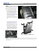
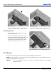
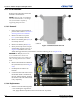
Figure 6-22 Memory Fan Assembly Replacement
1. Place the memory fan assembly in the chassis
slots (1 in Figure 6-22).
2. Press the release tabs at the green touch points
with the index fingers, while grasping the side of
the fan assembly with the remaining fingers.
Carefully lower the assembly into the chassis
until it clicks into place (2 in Figure 6-22).
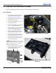
6.11 Memory
Removal and replacement of dual inline memory modules (DIMMs) is described here.
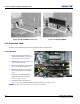
NOTE: The TVC-500 utilizes a single CPU. Ensure that any additional memory is only installed in the 6 slots
next to the installed CPU. (See Figure 6-24)
NOTICE:
Use only DDR3 DIMMs that are electrically and thermally compatible with the DIMMs
installed by Christie.
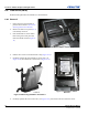
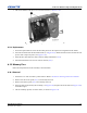
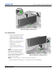
Figure 6-20 Memory Fan Assembly Release Figure 6-21 Memory Fan Assembly Removal