
User manual


Section 6: Chassis Component Replacement
TVC-500 Operation Manual 6-19
020-100539-01 Rev. 1 (08-2010)
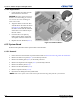
9. Prepare the chassis for system
board removal. Move the optical
drive out of the chassis far enough
to clear the system board (6.7.1).
Place the optical drive cables in the
bottom optical drive bay.
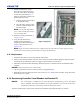
a. Place the expansion card cables
in the hard drive bays.
b. Place the CPU, memory power
and rear system fan cables over
the chassis edge.
NOTE: Use the CPU and memory
power cables to hold up the shorter
rear system fan cable.
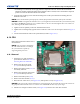
10. Slide the system board forward (1
in Figure 6-34).
11. Using the CPU heatsink as a
handle, lift the system board
straight up and then tilt the board to
remove it from the chassis (2 in
Figure 6-34).
NOTE: Figure 6-34 shows a dual processor configuration. The TVC-500 uses only a single processor
located closest to the memory fan assembly at the top of the illustration.
6.15.2 Replacement
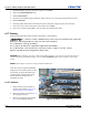
1. Ensure that the cables are clear of the bottom of the chassis.
2. Tilt the system board and lower it into the chassis, ensuring that all standoffs engage the chassis keyholes.
Ensure that the system board connectors engage correctly with the rear I/O panel.
3. Push back on the board while maintaining downward pressure on the board so that all standoffs remain
engaged.
NOTICE! Do not pinch any power or data cables.
4. Lift the system board corners to ensure the board is engaged properly.
5. Reinstall all removed components in the reverse order of 6.15.1 and reconnect all cables, using notes made
before removal as a guide.
6.16 Re-entering Controller Serial Number and Product ID
NOTICE: The serial number is loaded into the system during the manufacturing process and should
NOT be modified. This option should only be used by qualified service personnel. This value
should always match the serial number sticker located on the chassis.
After the system board is replaced, the controller serial number and product ID must be re-entered.
Figure 6-34 System