KICKER ROMA GB D Montage- und Bedienungsanleitung für Bestell-Nr. 92102 Assembly and exercise instructions for Order No.
D 1. 2. 4. 5. Inhaltsübersicht Wichtige Empfehlungen und Sicherheitshinweise Stückliste Montageanleitung Spielregeln GB Seite Seite Seite Seite 2 3 3 6 Contents - Page 7 6 Sehr geehrte Kundin, sehr geehrter Kunde Wir gratulieren Ihnen zum Kauf dieses Heimsport- und Spielgerätes und wünschen Ihnen viel Vergnügen damit. Bitte beachten und befolgen Sie die Hinweise und Anweisungen dieser Montage- und Bedienungsanleitung.
Technische Daten: Nach Öffnen der Verpackung bitte kontrollieren, ob alle Teile entsprechend der nachfolgenden Stückliste vorhanden sind. Ist dies der Fall, können Sie mit dem Zusammenbau beginnen. Wenn ein Bauteil nicht in Ordnung ist oder fehlt, oder wenn Sie in Zukunft ein Ersatzteil benötigen, wenden Sie sich bitte an: Stand: 01. 02.
Montageanleitung Bevor Sie mit der Montage beginnen unbedingt unsere Empfehlungen und Sicherheitshinweise beachten! Entnehmen Sie alle Einzelteile dem Karton und legen Sie diese auf eine saubere Unterlage, legen Sie ggf. die Transportpappe unter, damit die Oberflächen nicht zerkratzt werden. (Der Einsatz eines Akku-Schraubers mit Kreuzschlitz-Bit erleichtert und verkürzt die Montage erheblich.) Schritt 1: Montage des Grundrahmens.
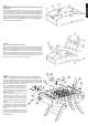
Deutsch Schritt 3: Montage der Ballauffangschalen, Ballrückgabeschalen und der Ballrücklaufrohre. Führen Sie die Ballauffangschalen für die Tore (7) an die entsprechende Position am Kopfseitenrahmen (3) und schrauben Sie diese mittels der Kreuzschlitzschrauben 4x12 (30) fest. Führen Sie die Ballrückgabeschalen (8) an die entsprechende Position am Längsseitenrahmen (2) und schrauben Sie diese mittels der Kreuzschlitzschrauben 4x12 mm (30) ebenso fest.
Schritt 6: Montage der Treffer-Zähleinheit, Ballwurfeinheit, Griffe und Stopfen. Schieben Sie die Griffe (16) mit Hilfe von etwas Seifenlauge wie in der Abb. gezeigt auf und versehen Sie alle übrigen Griffstangenenden mit einem Stopfen (17). Montieren Sie die Trefferzähl-Einheiten (11) an entsprechender Stelle mittels der Schrauben 4x45 mm (32) am Kopfseitenrahmen (3). Drehen Sie die Balleinwurfeinheit (9) in die Längsseitenrahmen (2) ein und sichern Sie die Position mittels der Schraube 4x16 mm (30).
GB Contents 1. Important Recommendations and Safety Instructions 2. Parts List 3. Assembly Instructions With Exploded Diagrams 4. Rules of the game: Page 7 Page 8 Page 9 - 11 Page 11 Dear customer, English We congratulate you on your purchase of this home training sports unit and hope that we will have a great deal of pleasure with it. Please take heed of the enclosed notes and instructions and follow them closely concerning assembly and use.
Parts List – Spare Parts List KICKER ROMA Order No. 92102 Technical data: Please check after opening the packing that all the parts shown in the following parts lists are there. Once you are sure that this is the case, you can start assembly. Please contact us if any components are defective or missing, or if you need any spare parts or replacements in future: Issue: 01. 02. 2012 Show Kicker with noticeable design.
Assembly Instructions English Before beginning with assembly, observe our recommendations and safety instructions! Remove all parts from the carton and assemble the kicker on a soft and clean surface – if necessary, place the transport carton underneath to avoid damaging/scratching the parts. You can shorten up the assembling time by using an electric. Screw driver with cross head bit if you have. Step 1: Assembly of main frame.
Step 3: Assembly of goal door, ball returns and ball return tubes. Put the goal doors (7) at the appropriate position at short side frame (3) and fix it with screws 4x12 (30). Put the ball returns (8) at the appropriate position at long side frame (2) and fix it with screws 4 x 12 (30) too. Connect the goal doors (7) and ball returns (8) with ball return tubes (12) through lengthen the tube. Step 4: Assembly of leg and leg-panel.
English Step 6: Assembly of counters, ball in cup, rubber handle and rod cap. Slide the rubber handle (16) as figure shows with help from a little bit soap water onto the grip rod and put on each end of grip rod a rod cap (17). Place the counters (11) in the right position of short side board (3) and fix it with screws 4x45 mm (32). Turn in the 2-piece ball in cup unit (9) at the hole at long side board (2) and secure with screw 4 x16 mm (30).
Bei Reklamationen, notwendigen Ersatzteilbestellungen oder Reparaturen wenden Sie sich bitte an unsere Service Abteilung. Service: Top-Sports Gilles GmbH Tel.: +49 (0)2051/6067-0 Friedrichstrasse 55 info@christopeit-sport.com Fax: +49 (0)2051/6067-44 D - 42551 Velbert http://www.christopeit-sport.