
Operation Manual


16
Assembly Instructions
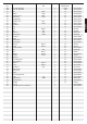
Remove all the separate parts from the packaging, lay them on the floor
and check roughly that all are there on the base of the assembly steps.
Please note that a number of parts have been connected directly to
the main frame and preassembled. In addition, there are several other
individual parts that have been attached to separate units. This will make
it easier and quicker for you to assemble the equipment.
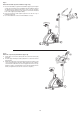
Step 1:
Attach the stabilizer (2+3) at main frame (1).
1. Attach the front foot (2) with the preassembled transport rollers (8) to the
main frame (1). Do this with the two screws M8x75 (7), curved washers
8//25 (6) and spring washers (22).
2. Attach the rear foot (3) with height adjustable foot caps (5) to the main
frame (1). Do this with the two screws M8x75 (7), curved washers 8//25
(6) and spring washers (22).
After assembly has been completed, you can compensate for minor
irregularities in the floor by turning the wheel at cap (5).
The equipment should be set up that the equipment does not move of
its own accord during a training session.
Step 2:
Attach the pedals (37L+37R) at pedal crank (25).
1. Screw the right pedal (37R) into the locator in the right-hand side (as
seen in operation) for the pedal crank (25) (Note! the screw direction is
clockwise).
2. Screw the left pedal (37L) into the locator in the left-hand side (as seen
in operation) for the pedal crank (25).
(Note! the screw direction is anti-clockwise).
3. Then mount the pedal straps left and right on the associated pedals
(37). (The pedals are signed with „L“ for Left and „R“ for Right.)