Heimsport-Trainingsgerät AP 1 GB D Montage- und Bedienungsanleitung für Bestell-Nr. 1100 Assembly and exercise instructions for Order No. 1100 F NL Notice de montage et d’utilisation du No.
D 1. 2. 3. 4. 5. 6. 7.
Deutsch
Stückliste - Ersatzteilliste Wenn ein Bauteil nicht in Ordnung ist oder fehlt, oder wenn Sie in Zukunft ein Ersatzteil benötigen, wenden Sie sich bitte an uns. AP 1 Best.-Nr. 1100 Technische Daten: Stand: 01. 04. 2011 • Magnet-Brems-System • ca.
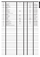
Bezeichnung Nr. Abmessung Menge Montiert an mm ET-Nummer Stück Abbildungs Nr.
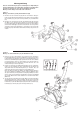
Montageanleitung Bevor Sie mit der Montage beginnen, unbedingt unsere Empfehlungen und Sicherheitshinweise beachten. Bitte entnehmen Sie alle Einzelteile dem Karton und prüfen Sie grob die Vollständigkeit anhand der Montageschritte. Einige Teile sind bereits vormontiert. Schritt 1: Montage der Fußrohre (54+58) am Grundrahmen (26). 1. Montieren Sie den vorderen Fuß (54) mit den vormontierten Transportrollen (53) am Grundgestell (26).
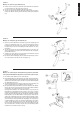
Schritt 3: Montage des Lenkers (2) am Stützrohr (13). Deutsch 1. Führen Sie den Lenker (2) zur geöffneten Lenkeraufnahme am Stützrohr (13) und schließen Sie diese über den Lenker (2). 2. Stecken Sie die Lenkerverkleidung (10) über den Lenker, 3. Stecken Sie das Distanzstück (9) auf die Sterngriffschraube (8) und befestigen Sie damit in gewünschter Position den Lenker (2) am Stützrohr (12). Schritt 4: Montage des Computers (1) am Stützrohr (13). 1.
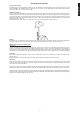
Schritt 6: Montage der Pedalen (45L+45R) an der Tretkurbel (48). 1. Schrauben Sie die rechte Pedale (45R) auf der in Fahrtrichtung rechten Seite befindlichen Pedalkurbel (48) ein (Achtung! Schraubrichtung: im Uhrzeigersinn). 2. Die linke Pedale (45L) schrauben Sie auf der in Fahrrichtung linken Seite in die Aufnahme der Pedalkurbel (48) ein. (Achtung! Schraubrichtung: entgegen dem Uhrzeigersinn).
Transport des Gerätes: Es befinden sich 2 Transportrollen im vorderen Fuß. Um das Gerät an einen anderen Ort zu stellen oder zu lagern, fassen sie den Lenker und kippen Sie das Gerät auf den vorderen Fuß so weit, sodass sich das Gerät leicht auf den Transportrollen bewegen lässt und schieben Sie es zum gewünschten Ort. Sitzhöhenverstellung: Um eine angenehme Sitzposition beim Training zu erhalten muss die Sitzhöhe richtig eingestellt werden.
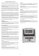
Computeranleitung für 1100 Achtung: Zur Pulsmessung müssen die beiden Kontaktflächen der PulsmessgriffEinheit (11) mit beiden Händen gleichzeitig gegriffen werden. Dabei sollten sich die Kontaktflächen mittig in der Handinnenfläche befinden. Der mitgelieferte Computer bietet den größten Trainingskomfort. Jeder trainingsrelevante Wert wird in einem entsprechenden Sichtfenster angezeigt.
Trainingsanleitung Deutsch Um spürbare körperliche und gesundheitliche Verbesserungen zu erreichen, müssen für die Bestimmung des erforderlichen Trainingsaufwandes die folgenden Faktoren beachtet werden: 1. Intensität: Die Stufe der körperlichen Belastung beim Training muß den Punkt der normalen Belastung überschreiten, ohne dabei den Punkt der Atemlosigkeit und /oder der Erschöpfung zu erreichen. Ein geeigneter Richtwert für ein effektives Training kann dabei der Puls sein.
GB 1. 2. 3. 4. 5. 6. 7. Contents Summary of Parts Important Recommendations and Safety Information Parts List Assembly Instructions With Exploded Diagrams Mount, Use & Dismount Computer instructions Training Instructions Page Page Page Page Page Page Page 3 12 13 - 14 15 - 17 18 19 20 Dear customer, We congratulate you on your purchase of this home training sports unit and hope that we will have a great deal of pleasure with it.
Parts List – Spare Parts List AP 1 Order No. 1100 Technical data: Please contact us if any components are defective or missing, or if you need any spare parts or replacements in future. Issue: 01. 04. 2011 Top-Sports Gilles GmbH Friedrichstr. 55 42551 Velbert Telefon: +49 (0) 20 51 - 6 06 70 Telefax: +49 (0) 20 51 - 6 06 74 4 e-mail: info@christopeit-sport.com www.christopeit-sport.com Illustration Designation No. English • Magnetic brake system • Aprox.
Illustration Designation No. 44 Dimensions Quantity mm Attached to ET number illustration No.
Assembly Instructions Remove all the separate parts from the packaging, lay them on the floor and check roughly that all are there on the basis of the following assembling steps. Please note that a number of parts have been connected directly to the main frame and preassembled. In addition, there are several other individual parts that have been attached to separate units. This will make it easier and quicker for you to assemble the equipment. Step 1: Attach the stabilizer (54 + 58) at main frame (26).
Step 3: Attach the handlebar (2) at handlebar support (13). 1. Guide the preassembled handlebar unit (2) through the upper part of the handlebar post (13) and close the bracket of handlebar holder. 2. Attach the handlebar cover (10) at the handlebar holder of handlebar support (13). 3. Screw the handlebar (2) in desired position at the handlebar post (13) with spacer (9) and handlebar screw (8). Step 4: Attach the computer (1) at handlebar support (13). 1.
Step 6: Attach the pedals (45L+45R) at pedal crank (48). English 1. Screw the right pedal (45R) into the locator in the right-hand side (as seen in operation) for the pedal crank (48) (warning! the screw direction is clockwise). 2. Screw the left pedal (45L) into the locator in the left-hand side (as seen in operation) for the pedal crank (48) (Warning! the screw direction is anti-clockwise). Step 7: Checks 1. Check the correct installation and function of all screwed and plug connections.
Mount, Use & Dismount Transportation of Equipment: There are two rollers equipped on the front foot. For moving, you can lift up the rear foot and drive it to where you would like to locate or store it. Adjustment – Seat Position For an effective workout, the seat must be adjusted properly. While your are pedaling, your Knees should be slightly bent when the pedals are in the farthest position. In order to adjust the seat, unscrew the knob few turns and draw it out slightly.
Computer instructions for 1100 Keys: The supplied computer allows the most convenient training. Every value relevant to training is displayed in a corresponding window. From the beginning of the training session, the required time, the current speed, the approximate calorie consumption, the travelled distance ad the current pulse rate are displayed. All values are counted from zero upwards. The speed is indicated on the upper display. All other values are indicated on the lower display.
Training instructions You must consider the following factors in determining the amount of training effort required in order to attain tangible physical and health benefits: 1. Intensity: The level of physical exertion in training must exceed the level of normal exertion without reaching the point of breathlessness and / or exhaustion. A suitable guideline for effective training can be taken from the pulse rate.
Sommaire F 1. Aperçu des pièces 2. Recommandations importantes et règles de sécurité 3. Nomenclature 4. Notice de montage avec écorchés 5. Monter, utiliser & descendre 6. Manuel d’utilisation du calculateur électronique 7. Recommandations pour l’entraînement Page Page Page Page Page Page Page 3 21 22 - 23 24 - 26 27 28 29 Chère cliente, cher client, Nous vous félicitons pour l’achat de ce cycle d’entraînement intérieur et nous vous souhaitons beaucoup de plaisir avec.
Liste des pièces- Liste des pièces de rechange AP 1 N° de commande 1100 Caractéristiques techniques : l l l l l l l l l Si une pièce n’est pas correcte, s’il manque une pièce ou si vous avez besoin d’une pièce de rechange à l’avenir, veuillez vous adresser à : Version du : 01/ 04/ 2011 Système de freinage magnétique Volant cinétique d’env.
Désignation n° 44 Dimensions Quantité Monté sur en mm Unités schéma n° Numéro ET Vis de câble plat 2 34 39-10172 45 L Pédale gauche 1 48 36-1100-05-BT 45 R Pédale droite 1 48 36-1100-06-BT 46 L Revêtement gauche 1 26+46R 36-1100-01-BT 46 R Revêtement droit 1 26+46L 36-1100-02-BT 47 Aimant 1 49 36-9613222-BT 48 Axe de pédalier 1 26 33-1100-06-SI 49 Roue à courroie 1 48 36-1100-12-BT 50 Câble plat 320J 1 32+49 36-1100-13-BT 51 Rondelle 22//35 1 48 36
Instructions de montage Sortez toutes les pièces de l’emballage, posez-les sur le sol et contrôlez si rien ne manque en vous basant sur la Etapes de cette Notice de montage et d’utilisation. Il faut tenir compte du fait que certaines pièces ont été reliées au cadre et prémontrées. Quelques autres pièces ont également déjà été jointes. Ceci afin de faciliter et d’accélérer le montage définitif. Etape n° 1: Montage du pied avant et arrière (54+58) 1.
Etape n° 3: Montage du guidon (2) Français 1. Dirigez le guidon (2) vers le logement ouvert du guidon, au niveau du tube support (13) et fermez-le au-dessus du guidon (13). 2. Attachez le revêtement pour de guidon (10) sur le guidon (2). 3. Placez une rondelle (9) sur la vis à oreilles (8) afin de pouvoir fixer le guidon (2) dans la position souhaitée, au niveau du tube support (13). Etape n° 4: Montage de l’ordinateur (1) 1.
Etape n° 6: Montage des pédales (45L+45R) 1. Vissez la pédale droite (45R) sur le support à droite (48), dans le sens de fonctionnement, de la manivelle de pédalier. (Attention! Serrage des vis: dans le sens d’horloge) 2. La pédale gauche (45L) doit ensuite être vissée dans le support de manivelle de pédalier (48), à gauche et dans le sens de fonctionnement. (Attention! Serrage des vis: dans le sens contraire d’horloge) Etape n°7: Contrôle 1.
Monter, utiliser & descendre Transport de la machine: La machine est équipée de 2 rouleaux sur le pied avant. Si vous voulez transporter la machine, soulevez le pied postérieur et roulez la machine vers la destination désirée. Attention: Veillez à ce que le bouton soit remis en position correcte et qu’il soit solidement vissé. Ne dépassez jamais la hauteur maximale de la selle. Descendez toujours de la machine avant de modifier un réglage. Monter, utiliser & descendre Monter : a.
Mode d’emploi de l’ordinateur 1100 Touches : 1. Touche „E“: Pour fixer préalablement et par étape des valeurs dans les fonctions individuelles, appuyer une fois sur cette touche. A cet effet, il faut d’abord sélectionner la fonction souhaitée à l’aide de la touche „F“. Si l’on appuie longuement, un déroulement rapide se produit lequel peut être ré interrompu en appuyant de nouveau. Dès le début de l’entraînement, le comptage s’effectue en arrière en partant de ces valeurs fixées. 2.
Recommandations pour l’entraînement Les facteurs ci-après doivent être pris en compte pour la détermination de l’entraînement indispensable afin d’améliorer concrètement son physique et sa santé: Français 1. Intensité: L’entraînement n’aura d’effets positifs que si les efforts déployés dépassent ceux de la vie quotidienne, mais sans être hors d’haleine et/ou se sentir épuisé. Le pouls peut constituer un repère valable pour un entraînement efficace.
Inhoudsopgave NL 1. 2. 3. 4. 5. 6. 7. Overzicht van de losse delen Belangrijke aanbevelingen en veiligheidsinstructies Stuklijst Montagehandleiding met explosietekeningen Opstappen, Gebruiken & Afstappen Handleiding bij de computer Trainingshandleiding pagina pagina pagina pagina pagina pagina pagina 3 30 31 - 32 33 - 35 36 37 38 Geachte klant Wij willen u van harte gelukwensen met de aanschaf van uw hometrainer en hopen dat u hier veel plezier aan zult beleven. Neem a.u.b.
Stuklijst - reserveonderdelenlijst AP 1 best.nr. 1100 Technische specificatie: Wanneer een bepaald onderdeel niet in orde is of ontbreekt, of wanneer u in de toekomst een reserveronderdeel nodig heeft, kunt u zich wenden tot: Stand: 01. 04. 2011 • • • • • • • • Magnetisch remsysteem met ca.
Afbeeldings- Beschrijving nr. 44 Afmetingen mm Aantal stuks Gemonteerd aan ET-nummer afbeeldingsnr.
Montagehandleiding Neem alle losse onderdelen uit de verpakking, leg deze op de grond en controleer aan de hand van de montage staps of alle onderdelen anwezig zijn. Hierbij moet er op worden gelet dat een aantal onderdelen rechtstreeks met het onderstel zijn verbonden en voorgemonteerd zijn. Bovendien zijn enkele andere losse delen ook al tot eenheden samengevoegd. Hierdoor kunt het apparaat gemakkelijker en sneller monteren.
Stap 3: Montage van de stuur (2) aan de stuurbuis (13). 1. Voer het stuur (2) door de geopende stuurhouder op de stuurframe (13) en sluit u deze over het stuur (6). 2. Plaatst de stuur bekleiding (10) aan de stuurhouder ob de stuurbuis (13). 3. Plaatst u een Afstandstuk (9) op de stergrep schroef (8) en hiermee bevestigd u het stuur (2) in de gewenste positie op stuurbuis (13). Stap 4: Montage van de computer (1) 1.
Stap 6: Montage van de pedalen (45L+45R) Nederlands 1. Schroef het rechter pedaal (45R) in de pedaalkruk (48) aan de zijde die tijdens de training rechts is. (Let op! De schroefrichting is in wijzerrichting). 2. Schroef het linker pedaal (45L) in de pedaalkruk (48) aan de zijde die tijdens de training links is. (Let op! De schroefrichting is in tegenwijzerrichting).
Opstappen, Gebruiken & Afstappen Transport van Apparaat: Aan de voorzijde bevinden zich twee rollers. Om het apparaat te verplaatsen kunt u de achterzijde van het apparaat optillen en sturen naar waar u wilt om het te plaatsen of te stallen. Aanpassen – Hoogte zadel Voor een effectieve workout, dient het zadel op de juiste hoogte te zijn afgesteld. Tijdens het trappen, dienen Uw knieën licht gebogen te zijn wanneer de pedalen in de verste positie staan.
Computerhandleiding voor 1100 Toetsen: 1. „E“-toets: Door telkens één keer kort op deze toets te drukken kunnen waarden in de afzonderlijke functies trapsgewijs worden ingesteld. Daarvoor moet eerst de gewenste functie met de ,,F‘‘-toets worden geselecteerd. Door deze toets langer ingedrukt te houden verspringen de waarden sneller, deze functie kan worden gestopt door de toets nogmaals in te drukken. Bij het begin van de work-out wordt dan vanaf de ingestelde waarde teruggeteld naar nul. 2.
Trainingshandleiding De onderstaande factoren moeten in acht worden genomen bij het bepalen van de benodigde training voor het bereiken van een merkbare verbetering van uw figuur en gezondheid: 1. Intensiteit: De mate van lichamelijke belasting bij de training moet de normale belasting overschrijden, zonder dat u daarbij buiten adem en/of uitgeput raakt. De hartslag kan een geschikte richtwaarde voor een effectieve training zijn.
Обзор содержания 1. 2. 3. 4. 5. 6. 7. Важные рекомендации и указания по безопасности Обзор отдельных деталей Спецификация Руководство по сборке с отдельными иллюстрациями Пользование тренажером Руководство по использованию компьютера Руководство по тренировкам ctp. стр. стр. 39 3 40 - 41 стр. стр. стр. стр. 42 - 44 45 46 47 Уважаемые покупательницы и покупатели! Поздравляем Вас с покупкой тренировочного снаряда для домашних занятий спортом и желаем Вам самых приятных впечатлений.
Спецификация - Список запасных частей AP 1 № заказа 1100 Технические характеристики Сняв упаковку, проверьте по списку, все ли детали на месте. Если все в порядке, то можно начинать сборку. Если какойнибудь агрегат не в порядке или отсутствует, обращайтесь к нам: По состоянию на 01.04.
№ Наименование Размеры в мм картинки Кол-во Монтируется на № ЕТ-№ штук 44 Натяжное устройство клинового ремня 2 34 39-10172 45 L Педаль слева 1 48 36-1100-05-BT 45 R Педаль справа 1 48 36-1100-06-BT 46 L Обшивка слева 1 26+46R 36-1100-01-BT 46 R Обшивка справа 1 26+46L 36-1100-02-BT 47 магнита 1 49 36-9613222-BT 48 шатуна 1 26 33-1100-06-SI 49 Приводной шкив 1 48 36-1100-12-BT 50 Плоский ремень 320J 1 32+49 36-1100-13-BT 51 Подкладная
Руководство по монтажу Прежде чем приступить к монтажу, внимательно прочитайте наши рекомендации и указания по безопасности! Выньте все части из упаковки, положите их на пол и проконтролируйте их на комплектность в соответствии с рисунками в инструкции по монтажу. Это поможет Вам при сборке тренажера. Шаг 1: Монтаж ножек (54+58) на основную раму (26). 1. Смонтируйте переднюю ножку (54) с транспортировочными роликами (53) на основную раму (26).
Шаг 3: Монтаж руля (2) на опорную трубу руля (13). 1. Подведите руль (2) к открытому креплению руля на опорной трубу руля (13) и закройте его над рулем (2). 2. Вставьте оболочки рукоятки (10) на руль (2). 3. Наденьте подкладную шайбу (9) на грибковый болт (8) и прикрути-те ими руль (2) к опорной трубе руля (13). Шаг 4: Монтаж компьютера (1) на опорную трубу руля (13). 1. Вставьте батарейки (2x Mignon AA 1,5V) в компьютер (1). (Батареи для компьютера не прилагаются в объеме поставок.
Шаг 6: Монтаж педалей (45L+45R) шатуны педалей (48). 1. Прикрутите правую педаль (45R) на шатун педали (48), находящийся с правой стороны в направлении движения. (Внимание! На-правление закручивания болта: по часовой стрелке). 2. Прикрутите левую педаль (45L) на шатун педали (48), находящий-ся с левой стороны в направлении движения. (Внимание! Направ-ление закручивания болта: против часовой стрелки). Шаг 7: Контроль 1. Проверьте все соединения на правильность сборки и проведите проверку функциональности.
Пользование тренажером Пользование тренажером На передней ножке находятся два транспортировочных ролика. Для того, чтобы передвинуть тренажер на другое место или поместить на место хранения, возьмитесь за руль и наклоните тренажер на переднюю ножку так, чтобы тренажер можно было легко передвинуть с помощью транспортировочных роликов на нужное место. Регулировка высоты седла: Для принятия удобного положения на седле во время тренировки, необходимо установить правильную высоту седла.
Руководство по использованию компьютера на тренажере серии 1100 для данной функции не производится. (Границы показаний 40- 240 ударов в минуту) Входящий в комплект оборудования тренажера компьютер обеспечит Вам максимальный комфорт во время тренировки. Любой важный для тренировочного процесса показатель отражается на дисплее. Внимание: Для измерения пульса необходимо одновременно взяться обеими руками за контактные поверхности ручек блока измерения пульса (11).
ИНСТРУКЦИЯ ПО ТРЕНИРОВКЕ Вы должны учитывать следующие факторы, чтобы определить верные параметры тренировок для достижения ощутимых физических результатов и пользы для здоровья. 1. Интенсивность Уровень физических нагрузок при тренировках должен превышать уровень нормальных физических нагрузок, но вы не должны задыхаться и сильно переутомляться. Удобной мерой эффективности тренировки может служить частота пульса.
Bei Reklamationen, notwendigen Ersatzteilbestellungen oder Reparaturen wenden Sie sich bitte an unsere Service Abteilung. Service: Top-Sports Gilles GmbH Tel.: +49 (0)2051/6067-0 Friedrichstrasse 55 info@christopeit-sport.com Fax: +49 (0)2051/6067-44 D - 42551 Velbert http://www.christopeit-sport.