
User's Manual

2
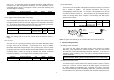
Function Description Indication
1. Have Z-Wave Controller entered
association mode.
2. When pressing link key 3 times within
1.5 seconds will enter association
mode.
Detector beeps when link
key is pressed.
Association
3. There are two groupings – 1 and 2.
Refer to Z-Wave’s Grouping as
described on page 4.
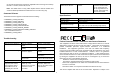
Including a node ID allocated by Z-Wave Controller means inclusion. Excluding a node
ID allocated by Z-Wave Controller means exclusion.
Failed or success in including/excluding the node ID can be viewed from the Z-Wave
Controller.
Choosing a Mounting Location
The Motion Detector can be mounted either on a wall. Before selecting a position
for Motion Detector, the following points should be noted:
1. Do not position the detector facing a window/fan/air-conditioner or direct
sunlight.
2. Do not position the detector directly above or facing any source of heat, e.g.
fires, radiators, boiler etc.
3. Ensure the detector is positioned in place where the light source detected by
the detector is consistent with actual ambient illumination. Do not locate the
detector in a shadowy place.
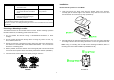
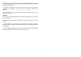
4. Where possible, mount the detector so that the logical path of an intruder would
cut across the fan pattern rather than directly towards the detector (FIGURE 1).
5. For best results, locate the detector directly facing an entrance.
Installation
Ensure that the system is in Test Mode.
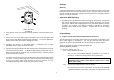
1. Undo and remove the fixing screw from the bottom edge of the detector.
Carefully pull the bottom edge of the detector away from the rear cover and
then slide down to release the top clips. (FIGURE 2)
FIGURE 2
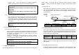
2. Carefully drill out the required mounting holes in the rear cover using 3mm drill
according to whether the unit is being mounted in a corner or against a flat wall.
Note: Using 1
st
mounting hole to fulfill corner mounting installation, while 2
nd
mounting hole for flat wall installation. (FIGURE 3a & 3b)
FIGURE 3a
FIGURE 1