
User's Manual

3
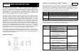
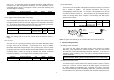
Corner mounting
FIGURE 3b
3. Using the rear cover as a template, mark the positions of the fixing holes on the
wall.
4. Fix the rear cover to the wall using the two 18mm No.4 screws and 25mm wall
plugs, (a 5mm hole will be required for the wall plugs). Do not over-tighten the
fixing screws as this may distort or damage the cover.
5. Configure the detector as described below. Remember that on initial
installation that the device needs to be tested.
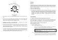
6. Check that the detector PCB is located and set in the correct position to provide
the required detection range. To adjust the PCB position, simply slide it up or
down ensuring that the location legs are aligned with the required position
number marked on the board.
7. To refit the detector to the rear cover and locate the clips in the top edge into the
rear cover. Push the lower edge of the detector into place and refit the fixing
screw in the bottom edge of the detector to secure in position. Do not
over-tighten the fixing screws as this may damage the casing.
Settings
Warm-Up
It will take approximately 2 minutes to warm up after battery has been connected.
During this period, the red LED will flash in every 3 seconds. When the red LED
turns on steadily for 5 seconds, it implies warm-up procedure is completed and the
detector is ready for detection.
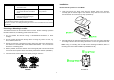
Operation Wall Mounting
1. By walking into a protected area within coverage of 110 degrees, the detector
will now be triggered each time the detector senses movement. The orange
LED on the detector will be illuminated and the associated appliances will be
activated. For example, siren will be sounded or indication of movement
detection will be shown on the controller. It implies that the unit is working
properly.
Programming
1. Z-Wave’s Group (Association Command Class Version 1)
The unit supports two association groups with one node support for Grouping 1 and
three nodes support for Grouping 2. This has the effect that when the unit is
triggered, all devices associated with the unit will receive the relevant reports.
There are two kinds of reports: ALARM_REPORT and
SENSOR_BINARY_REPORT.
1-1 Grouping 1 (Max. node = 1)
1-1-1 Power Applied Command
The unit will send ALARM_REPORT command to the nodes of
Grouping 1 to inform the device that the unit is powered up.
ALARM_REPORT Command:
[Command Class Alarm, Alarm Report, Alarm Level = 0x02,
Alarm Type = 0x01]
1-1-2 Intrusion Event Report (Binary Sensor Report)
Once the Detector detected a movement, the unit will send SENSOR
_ BINARY_REPORT to the nodes of Grouping 1 to inform there is an