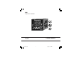
604 Temperature Controller Chromalox 1604 r USER'S MANUAL Issue date May 2000 1604-0-BC.
CONTENTS MOUNTING REQUIREMENTS ........................... 1 OUTLINE AND CUT OUT DIMENSIONS ........... 2 CONNECTION DIAGRAMS ................................ 3 PRELIMINARY HARDWARE SETTINGS ........... 9 CONFIGURATION PROCEDURE .................... 10 OPERATIVE MODE .......................................... 18 Display function .......................................... 18 Indicators ................................................... 18 Pushbutton function during operating mode ...........................
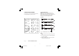
Model identification Model 1604 1/16 DIN Temperature Controller Code 1 6 Output 1 - Heat or Cool Relay, 3 Amps at 250 Vac (Resistive) SSR Drive, 14 Vdc at 20 mA Code 1 Output 2 - Alarm Relay, 2 Amp at 250 VAC (Resistive load) Code 0 None 1 Out #3, 2 Amps at 250 V AC (Resistive load) 2 Heater Break Down input, Out #3 3 RS 485 Digital communications, Out #3 4 RS 485 Digital comm.
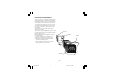
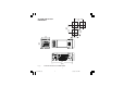
MOUNTING REQUIREMENTS Select a location, for instrument mounting, where minimum vibrations are present and the ambient temperature is within 0 and 50 °C (32 and 122°F). The instrument can be mounted on a panel up to 15 mm thick with a square cutout of 45 x 45 mm. For outline and cutout dimensions refer to Fig. 2. The surface texture of the panel must be better than 6,3 mm. The instrument is shipped with rubber panel gasket (50 to 60 Sh).
3.0 (75) OUTLINE AND CUT OUT DIMENSIONS 2.4 (60) 1.77 (45) 1.9 (48) 1.77 (45) 2.2 (56) 4.8 (122) Fig. 2 OUTLINE AND CUT-OUT DIMENSIONS 2 1604-1-BC.
A) MEASURING INPUTS NOTE: Any external component (like zener barriers etc.) connected between sensor and input terminals may cause errors in measurement due to excessive and/or not balanced line resistance or possible leakage currents. CONNECTION DIAGRAMS Connections are to be made with the instrument housing installed in its proper location.
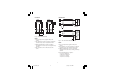
LINEAR INPUT RTD INPUT RTD 10 RTD + _ 9 mA, mV or V Shield + 10 8 9 10 8 9 10 _ 9 Fig. 5 RTD INPUT WIRING G NOTE: 1) Don’t run input wires together with power cables. 2) Pay attention to the line resistance; a high line resistance may cause measurement errors. 3) When shielded cable is used, it should be grounded at one side only to avoid ground loop currents. 4) The resistance of the 3 wires must be the same. Fig.
B.1) LOGIC INPUT B.2) CURRENT TRANSFORMER INPUT This instrument can use the input "IN CT/SPSP2" (connections 14 and 15) as current transformer input or logic input. This instrument can use the input "IN CT/SPSP2" (connections 14 and 15) as current transformer input or logic input. Safety note: 1) Do not run logic input wiring together with power cables. 2) Use an external dry contact capable of switching 0.5 mA, 5 V DC. 3) The instrument needs 100 ms to recognize a contact status variation.
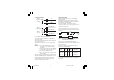
C) RELAY OUTPUTS OUT 1 (heating or cooling) 6 NO 7 OUT 2 (cooling /AL1) 1 2 OUT 3 (AL 2) 3 INDUCTIVE LOADS High voltage transients may occur switching inductive loads. Through the internal contacts these transients may introduce disturbances which can affect the performance of the instrument. For all the outputs, the internal protection (varistor) assures a correct protection up to 0.5 A of inductive component.
SERIAL INTERFACE RS-485 interface allows to connect up to 30 devices with one remote master unit. VOLTAGE OUTPUTS FOR SSR DRIVE I N S T R U M E N T + 6 OUT 1 _ + _ 7 SOLID STATE RELAY Fig. 11 SSR DRIVE OUTPUT WIRING It is a time proportioning output. Logic level 0: Vout < 0.5 V DC. Logic level 1: - 14 V + 20 % @ 20 mA - 24 V + 20 % @ 1 mA. Maximum current = 20 mA. 11 12 13 A/A' A'/A B/B' B'/B COMMON Fig. 12 - RS-485 WIRING The cable length must not exceed 1.5 km at 9600 BAUD.
D) POWER LINE WIRING POWER LINE 100 V to 240 V A.C (50/60Hz) or 24 V AC/DC P (L1) 5 N (L2) P (L1) N (L2) 4 and within easy reach of the operator; - it shall be marked as the disconnecting device for the equipment. NOTE: a single switch or circuit-breaker can drive more than one instrument. 9) When a neutral line is present, connect it to terminal 4 Fig.
OPEN INPUT CIRCUIT This instrument is able to identify the open circuit for TC and RTD inputs. The open input circuit condition for RTD input is shown by an "overrange" indication. For TC input, it is possible to select overrange indication (standard) or underrange indication setting the CH101 and SH101 according to the following table: Overrange (STD) CH101 = close SH101 = open Underrange CH101 = open SH101 = close PRELIMINARY HARDWARE SETTINGS 1) Remove the instrument from its case.
SELECTION OF THE "IN CT/SP-SP2" FUNCTION This instrument can use the input "IN CT/SP-SP2" (connections 14 and 15) as current transformer input or a logic input. The current transformer input allows to measure and display the current running in the load driven by the OUTPUT1 during the ON and OFF period of the OUT 1 cycle time. By this feature it is also available the "OUT 1 failure detection" function (see page 20).
23 = TC type R range 0 / +3200 °F 24 = TC type S range 0 / +3200 °F 25 = RTD type Pt 100 range -199.9 / +400.0 °F 26 = RTD type Pt 100 range -330 / +1470 °F 27 = TC type T range -199.9 / +400.0 °C 28 = TC type T range -330 / +750 °F NOTE: selecting P1 = 0, 2, 4, 9, 25 or 27, the instrument set automatically P36 = FLtr. For all the remaining ranges it will set P36 = nOFL. If a different selection is desired, P36 may be modified.
2 = it is used as alarm 1 output and the alarm 1 is programmed as band alarm. 3 = it is used as alarm 1 output and the alarm 1 is programmed as deviation alarm. 4 = it is used as second control output (Cooling output). NOTE: setting P7 = 4, the P6 parameter is forced to "rEV". The initial and full scale values determine the input span which is used by the PID algorithm, the SMART and the alarm functions.
NOTE:The "Out 1 failure detection" function assumes only the selected reset type (manual or automatic). energized during the ON status of the instrument output (relay energized or SSR output status 1). n.C. = Set P10 to n.C. when the load is energized during the OFF status of the instrument output (relay de-energized or SSR output status 0). P14 = Programmability of the alarm 2 threshold and hysteresis values Available only when P12 is different from 0.
P19 = Alarm 1 action Available only when P7 is different from 0 or 4. dir = direct action (relay energized in alarm condition) rEV = reverse action (relay deenergized in alarm condition) P18 = Safety lock 0 = No parameter protection. The device is always in unlock condition and all parameters can be modified. 1 = The device is always in lock condition and no parameter (exception made for the set points [SP/SP2] and alarm manual reset) can be modified (for SMART status see P27).
P28 = Relative cooling gain calculated by SMART function. This parameter is present only if P7 = 4 and P27 is different from 0. OFF = SMART algorithm does not calculate the rC parameter value On = SMART algorithm calculates the rC parameter value. P23 = OFFSET adjustment added to the measured value This parameter allows to set a constant OFFSET throughout the readout range. It is skipped for linear inputs - For readout ranges with decimal figure, P23 is programmable from -19.9 to 19.9.
P32 = Minimum value of the integral time calculated by the SMART algorithm. This parameter is present only if P27 is different from 0. It is programmable from 1 second (00.01) to 2 minutes (02.00). 2 = Safety value applied when overrange condition is detected. 3 = Safety value applied when underrange condition is detected.
P42 = Operative set point alignment at instrument start up 0 = At start up, the operative set point will be aligned to SP or SP2 according to the digital input status. 1 = At start up, the operative set point will be aligned to the measured value, the selected set point value will be reached by the programmed ramp (see Grd1 and Grd2 operative parameters). NOTE: if the instrument detects an out of range or an error condition on the measured value it will ever operate as described for P42 = 0.
OPERATIVE MODE When no pushbutton are pressed during the time out (see P35), the display will automatically return in "Normal Display Mode". In order to keep the desired information continuously on the lower display, depress s or t push-button to remove the timeout. When return in "Normal Display Mode" is desired, push FUNC push-button again. 1) Remove the instrument from its case. 2) Set the internal dip switch V101 in closed condition 3) Re-insert the instrument. 4) Switch on the instrument.
o During MANUAL mode, it allows to decrease the output value. s+FUNC = when device is in normal display mode, they allow to enable/disable the control output (see "Enable/ disable the control output" paragraph). s+MAN = During parameter modification they allow to jump to the maximum programmable value. t+MAN = During parameter modification they allow to jump to the minimum programmable value. SP2 = Flashing at slow rate when SP2 is used. Flashing at fast rate when a set point from serial link is used.
ENABLE/DISABLE THE CONTROL OUTPUT When the instrument is in "normal display mode", by keeping depressed for more than 5s s and FUNC pushbuttons, it is possible to disable the control outputs. In this open loop mode the device will function as an indicator, the lower display will show the word OFF and all control outputs will also be in the OFF state. When the control outputs are disabled the alarms are also in non alarm condition. The alarm outputs conditions depend on the alarm action type (see P19-P21).
MANUAL FUNCTION The MANUAL mode function can be accessed (only if enabled by P26=On) by depressing the MAN pushbutton for more than 1 sec. The command is accepted and executed only if the display is in "Normal Display Mode". When in MANUAL mode the LED's MAN annunciator will light up while the lower display shows the power output values. The value of OUT 1 is shown in the two most significant digit field while the value of OUT 2 (if present) is shown in the two less significant digit field.
LAMP TEST When it is desired to verify the display efficiency, push FUNC pushbutton for more than 10 s. The instrument will turn ON, with a 50 % duty cycle, all the LEDs of the display (we define this function "LAMP TEST"). No time out is applied to the LAMP TEST. When it is desired to come back to the normal display mode, push FUNC pushbutton again. During the LAMP TEST the instrument continues to control the process but no keyboard functions are available (exception made for the FUNC pushbutton).
OPERATIVE PARAMETERS Push the FUNC pushbutton, the lower display will show the code while the upper display will show the value or the status (ON or OFF) of the selected parameter. By s or t pushbutton it is possible to set the desired value or the desired status. Pushing the FUNC pushbutton, the instrument memorizes the new value (or the new status) and goes to the next parameter. Some of the following parameter may be skipped according to the instrument configuration. AL1 Param.
HyS ti td IP Cy1 Cy2 rC Note:When device is working with SMART algorithm the Pb value will be limited by P29, P30 and P31 parameters. Hysteresis for ON/OFF control action This parameter is available only when Pb=0. Range: from 0.1% to 10.0% of the input span. Integral time This parameter is skipped if Pb=0 (ON/ OFF action). Range: from 00.01 to 20.00 [mm.ss].
OLH tOL Hbd SCA Output high limit Range: - From 0 to 100 % when device is configured with one control output. - From -100 to 100% when device is configured with two control outputs. Time duration of the output power limiter (soft start) Range: from 1 to 540 min.Above this value the display shows “InF” meaning that the limiting action is always on Note: The tOL can be modified but the new value will become operative only at the next instrument start up.
When P37 is different from zero and an out of range condition is detected, the instrument operates in accordance with P37 and P38 parameters. ERROR MESSAGES OVERRANGE, UNDERRANGE AND SENSOR LEADS BREAK INDICATIONS The device is capable to detect a fault on the process variable (OVERRANGE or UNDERRANGE or SENSOR LEADS BREAK).
201 - 2xx 301 305 307 310 311 312 313 400 500 502 510 Configuration parameter error. The two less significant digits shown the number of the wrong parameter (ex.
EN 50081-2 and EN 50082-2) and to council directives 73/23/EEC and 93/68/EEC (reference harmonized standard EN 61010-1). Installation category: II Temperature drift: (CJ excluded) < 200 ppm/°C of span for mV and TC ranges 1, 3, 5, 6, 19, 20, 21, 22. < 300 ppm/°C of span for mA/V < 400 ppm/°C of span for RTD range 10, 26 and TC range 0, 2, 4, 27, 28. < 500 ppm/°C of span for RTD range 9 and TC ranges 7,8, 23, 24. < 800 ppm/°C of span for RTD range 25. Operative temperature: from 0 to 50 °C (+32 to 122 °F).
C) LINEAR INPUTS Read-out: keyboard programmable between -1999 and +4000. Decimal point: programmable in any position Burn out: the instrument shows the burn out condition as an underrange condition for 4-20 mA, 1-5 V and 2-10 V input types. It shows the burn out condition as an underrange or an overrange condition (selectable by soldering jumper) for 0-60 mV and 12-60 mV input types. No indication are available for 0-20 mA, 0-5 V and 0-10 V input types.
E) CURRENT TRANSFORMER INPUT FOR OUT1 FAILURE DETECTION The instruments equipped with this feature are capable, by means of a CT, to detect and signal a possible failure of the line driven by out 1 (see "OUT 1 failure detection"). Input range: 50 mA AC. Scaling: programmable from 10 A to 100 A (with 1 A step). Resolution: - for full scale up to 20 A: 0.1 A. - for full scale from 21 A to 100 A: 1 A Minimum duration of the period (ON or OFF) to perform the measurement: 400 ms.
Output status indication: Two indicators (OUT 1 and OUT 2) are lits when the respective output is in ON condition. Output level limiter: - For one control medium : from 0 to 100 % . - For two control mediums : from -100 to +100 % . This function may be operative at instrument start up for a programmable time (To avoid thermal shock and/or preheating the plant) otherwise it can be enabled by an external contact. Cycle times: - For out 1 it is programmable from 1 to 200 s.
MAINTENANCE 1) REMOVE POWER FROM THE POWER SUPPLY TERMINALS AND FROM RELAY OUTPUT TERMINALS 2) Remove the instrument from case. 3) Using a vacuum cleaner or a compressed air jet (max. 3 kg/cm2) remove all deposit of dust and dirt which may be present on the louvers and on the internal circuits trying to be careful for not damage the electronic components.
The following is a list of the default operative parameters loaded during the above procedure: DEFAULT PARAMETERS DEFAULT OPERATIVE PARAMETERS PARAMETER The control parameters can be loaded with predetermined default values. These data are the typical values loaded in the instrument prior to shipment from factory. To load the default values proceed as follows: SP SnRT n.RSt SP2 nnn AL1, AL2 a) The internal switch (V101, see fig. 14) should be closed. b) The SMART function should be disabled.
DEFAULT CONFIGURATION PARAMETERS tb 1 The configuration parameters can be loaded with predetermined default values. These data are the typical values loaded in the instrument prior to shipment from factory. To load the default values proceed as follows: dFLt f) Press FUNC pushbutton; the display will show: LOAd a) The internal switch should be open. b) The upper display will show: It means that the loading procedure has been initiated.
P17 P18 P19 P20 P21 P22 P23 P24 P25 P26 P27 P28 P29 P30 P31 P32 P33 P34 P35 P36 P37 P38 P39 P40 P41 P42 0 0 rEV OFF rEV OFF 0 Not available On On 2 OFF 30 1.5 1.0 00.50 0 Not available tn 10 nO.FL 0 0 10 PId Fn.Sp 0 0 0 rEV OFF rEV OFF 0 Not available On On 2 OFF 30 1.5 1.0 00.50 0 Not available tn 30 nO.FL 0 0 10 PId Fn.Sp 0 A. 3 1604-A-BC.
1604-A-BC.
170.IU0.160.400 Chromalox® INSTRUMENTS AND CONTROLS 1382 HEIL QUAKER BOULEVARD LAVERGNE, TN 37086-3536 PHONE (615) 793-3900 FAX (615) 793-3563 WIEGAND INDUSTRIAL DIVISION EMERSON ELECTRIC CO. 1604-A-BC.