
Installation guide

INSTALLATION GUIDE
BNC-2110
BNC Adapter for E/M/S Series and Analog Output Series Devices
This installation guide describes how to install and configure your BNC-2110 accessory with 68-pin or
100-pin E/M/S Series or 68-pin NI 671x/672x/673x Analog Output (AO) Series multifunction data
acquisition (DAQ) devices. This document also contains accessory specifications.
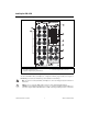
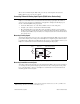
The BNC-2110 is ideal for simplifying connections between your measurement apparatus and your
DAQ device in laboratory, test, and production environments. The BNC-2110 has the following features:
• 15 BNC connectors for analog input, analog output, trigger/counter functions, and user-defined
signals
• A spring terminal block with 30 pins for digital and timing I/O signal connections
• A 68-pin I/O connector that connects to multifunction DAQ devices
• Can be used on a desktop or mounted on a DIN rail
Contents
Conventions ......................................................................................................................................... 1
What You Need to Get Started ............................................................................................................ 2
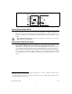
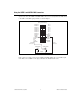
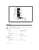
Installing the BNC-2110...................................................................................................................... 3
Connecting Differential Analog Input Signals (E/M/S Series Devices Only)..................................... 5
Measuring Floating Signals ......................................................................................................... 5
Measuring Ground-Referenced Signals....................................................................................... 5
Connecting Analog Output Signals ..................................................................................................... 6
Connecting APFI 0/AO EXT REF Signals.......................................................................................... 6
Connecting Trigger/Counter Signals ................................................................................................... 7
Connecting Digital and Timing I/O Signals ........................................................................................ 7
Using the USER 1 and USER 2 BNC Connectors .............................................................................. 9
Specifications....................................................................................................................................... 10
Conventions
The following conventions are used in this document:
<> Angle brackets that contain numbers separated by an ellipsis represent a range of values
associated with a bit or signal name—for example, AO <3..0>.
» The » symbol leads you through nested menu items and dialog box options to a final action.
The sequence File»Page Setup»Options directs you to pull down the File menu, select the
Page Setup item, and select Options from the last dialog box.
This icon denotes a note, which alerts you to important information.
This icon denotes a caution, which advises you of precautions to take to avoid injury, data loss,
or a system crash. When this symbol is marked on a product, refer to the Read Me First: Safety
and Radio-Frequency Interference document for information about precautions to take.