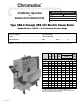
Chromalox ® Installation, Operation SERVICE REFERENCE DIVISION and RENEWAL PARTS IDENTIFICATION 4 SALES REFERENCE SECTION CES PQ444-1 (Supersedes PQ444) 161-562789-002 MAY, 1999 DATE Type CES-6 through CES-180 Electric Steam Boiler Standard Trim is 100 PSI — 0-90 Operating Pressure Range Boiler Serial Number . . . . . . . . . . . . . . . . . . . . . . . . . . . . . . . . Power Circuit Voltage . . . . . . . . . . . . . . . . . . . . . . . . . . . . . . . . . . Model . . . . . . . . . . . . . .
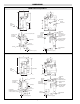
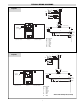
DIMENSIONS MODEL CES-6 through CES-18 B A L C Drain Blowdown Valve K Check Valve Optional Transformer H G E D F Steam Outlet I Pump/Solenoid Connection Conduit Box J Operating Pressure Control Control Circuit On-Off Switch with Pilot Light Safety Valve Outlet Manual Reset High Limit Control Optional Vacuum Breaker McDonnell & Miller Low Water Cutoff Pump Control Sight Glass Element Access Door Element Drain Blowdown Valve 1-1/4" 5/8" 7/16" Bolt Hole (typical) 7/16" Bolt Hole (typical) MOD
DIMENSIONS B* C CES — Dimensions (In.) D E F G H I Model A CES-6 37 22-1/2 30 15-1/4 20 30-1/2 9-1/2 16 1/2 CES — Dimensions (In.
WIRING your contractor or electrical dealer for recommended type for your system. 5. Be sure all electrical connections are sufficiently tightened. 6. WARNING: Substitution of components or modification of wiring system voids the warranty and may lead to dangerous operating conditions. 7. SPECIAL INSTRUCTIONS FOR CUSTOMERS SUPPLYING THEIR OWN CONDENSATE OR PUMP SYSTEMS. A. Check the voltage of the motor before making the wiring connection. Some Chromalox boilers are supplied with dual voltage systems.
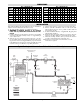
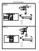
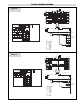
TYPICAL WIRING DIAGRAMS L1 L2 L3 Diagram 2 1 HTR C1 1L1 FU2 1L2 2 GND FU3 1L3 2 HTR C2 2L1 FU4 2L2 FU5 2L3 FU6 FU8 2 GND C1 FU 123 C2 FU 426 FU9 H1 H3 H2 H4 X2 X4 1PB Optional Transformer 1 GND 12 2TB Feed Water Electrical Connection 3 GND FU7 1TB 1 GND FU1 3 GND X1 1 X3 2 2 1 B FU9 B 1PB On W 1LT BR Off IFS Boiler On R Y Feed Water 1PS O 1 HTR Cabinet Exterior Left Side O 2PS O C1 2 HTR Heater Contactors C2 Wire Color Code B = Black BR = Brown R = R
TYPICAL WIRING DIAGRAMS Diagram 4 1 GND L1 L2 L3 1 HTR C1 2 GND 2 HTR FU7 FU2 FU8 3L2 1L3 FU3 FU9 1L3 C2 2L1 FU5 2L3 FU6 FU10 3 GND 12 2TB Feed Water Electrical Connection 3 GND C3 FU 123 FU 456 FU 789 X1 X3 1 2 2 B FU12 B 1PB On W 1LT BR Off IFS Boiler On R Y Feed Water 3 Htr O 1 HTR Cabinet Exterior Left Side X2 X4 1 1 GND C2 H4 Optional Transformer 1PB 2 GND C1 FU11 H3 H2 H1 FU12 3 HTR 3L1 FU4 2L2 2 GND 1TB C3 FU1 1L2 1L1 1PS 2PS O O Heate
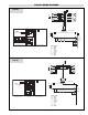
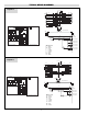
TYPICAL WIRING DIAGRAMS Diagram 6 1 GND L1 L2 L3 1 HTR C1 1L1 1L2 2 GND 1L3 2 HTR C2 FU1 FU7 FU2 FU8 FU3 FU9 C3 3L2 1L3 C4 FU4 FU10 2L2 FU5 FU11 4L2 2L3 FU6 FU12 4L3 2L1 3 HTR 3L1 4 HTR 4L1 FU14 FU13 H2 H2 Feed Water Electrical Connection 3 GND 12 2TB H1 1TB FU15 1PB C2 FU 1 2 3 FU 4 5 6 W IFS Boiler On R Y Feed Water 4 Htr 1 HTR 1LT BR Off 3 Htr FU 10 11 12 2 2 B FU15 B 1PB On C4 FU 7 8 9 X4 1 2 GND C3 X2 X3 1 1 GND C1 Optional Transformer
TYPICAL WIRING DIAGRAMS Diagram 8 L1 L2 L3 1 HTR 1L1 1L2 1L3 C1 2 HTR 2L1 2L2 2L3 C2 3 HTR 3L1 3L2 3L3 C3 FU7 FU8 FU9 4 HTR 4L1 4L2 4L3 C4 FU10 FU11 FU12 2 GND FU1 FU2 FU3 FU13 FU14 FU15 C5 5L1 5 HTR 5L2 5L3 FU4 FU16 C6 FU5 FU6 FU17 FU18 6L1 6 HTR 6L2 6L3 FU20 FU19 C1 FU 4 5 6 1TB 1PB 2TB 1 2 FU21 Optional Transformer 3 GND 3 GND C3 C2 FU 1 2 3 1 GND Feed Water Electrical Connection 2 GND FU 7 8 9 X1 1 C5 C6 FU 10 11 12 FU 13 14 15 FU 16 17 18 Cabinet Exteri
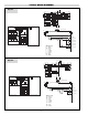
TYPICAL WIRING DIAGRAMS Diagram 10 L1 L2 L3 1 GND 1L1 1L2 1L3 C1 FU1 FU2 FU3 FU13 FU14 FU15 C5 5L1 5 HTR 5L2 5L3 2L1 2L2 2L3 C2 FU4 FU16 C6 FU5 FU6 FU17 FU18 6L1 6 HTR 6L2 6L3 3 HTR 3L1 3L2 3L3 C3 FU7 FU8 FU9 FU13 FU20 FU21 C7 7L1 7 HTR 7L2 5L3 4 HTR 4L1 4L2 4L3 C4 FU10 FU22 C8 FU11 FU12 FU23 FU24 8L1 6 HTR 8L2 8L3 1 HTR 2 HTR 2 GND FU25 C5 1 GND Feed Water Electrical Connection 16 17 18 2TB 1 2 FU27 19 20 21 C1 C2 C3 C4 1 2 3 4 5 6 7 8 9 10 11 12 5 HTR 6
TYPICAL WIRING DIAGRAMS Diagram 12 L1 L2 L3 1L1 1L2 1L3 C1 FU1 FU2 FU3 FU13 FU14 FU15 C5 5L1 5 HTR 5L2 5L3 2 HTR 2L1 2L2 2L3 C2 FU4 FU16 C6 FU5 FU6 FU17 FU18 6L1 6 HTR 6L2 6L3 3 HTR 3L1 3L2 3L3 C3 FU7 FU8 FU9 FU19 FU20 FU21 C7 7L1 7 HTR 7L2 5L3 4 HTR 4L1 4L2 4L3 C4 FU10 2 GND 1 GND Feed Water Electrical Connection 2TB 1 2 1TB C5 C6 C7 13 14 15 16 17 18 19 20 21 FU24 FU22 H1 3 GND 2 GND C2 C3 FU FU FU 1 2 3 4 5 6 7 8 9 C4 FU 10 11 12 X2 X4 Optional Transfor
TYPICAL WIRING DIAGRAMS Diagram 14 Typical Export Boiler 346V 3Ø 50 HZ L1 L2 L3 1L1 1L2 1L3 C1 FU1 FU2 FU3 FU7 FU8 FU9 C3 3L1 3 HTR 3L2 3L3 2 HTR 2L1 2L2 2L3 C2 FU4 FU5 FU6 FU10 FU11 FU12 C4 4L1 4 HTR 4L2 4L3 2 GND 1 2 2TB Feed Water Electrical Connection C1 C2 C3 C4 FU 1 2 3 FU 4 5 6 FU 7 8 9 FU 10 11 12 1TB 2 GND 3 GND FU13 1 GND 1 HTR 1PB 1CR 1 GND 220 VAC Single Phase Control Circuit 3 HTR 4 HTR 1 HTR 2 HTR 3 GND 1 2 B FU13 1PB On B Off Cabinet Exterior Left Side
OPERATION To check operation of the controls, close steam outlet valve and adjust operating pressure control to a low pressure setting. Also, set high limit control at 10 psig above operating pressure control. Turn on boiler, and allow pressure to build up. When pressure gauge reading approaches set point of pressure control, the switch will trip and shut off boiler. Turn off boiler.
OPERATION AUTOMATIC BLOWDOWN INSTRUCTIONS (IF FURNISHED) The Automatic Blowdown is a device which automatically starts up your boiler in the morning; shuts it down at night and blows down (partially drains) the main boiler drain and the low water cut-off column for a predetermined time interval each working day. The heart of the unit is an electrically operated straight through type ball valve.
OPTIONAL EQUIPMENT FOR STEAM BOILERS AUXILIARY LOW WATER CUTOFF Operation Operation of this control is accomplished by sensing a minute AC current flowing between submerged contact probe in the boiler shell. When this minute AC current is conducted through an external circuit resistance up to 40,000 ohms or less, a signal of sufficient magnitude is present to trigger the SCR and, in turn energize the control relay.
OPTIONAL EQUIPMENT FOR STEAM BOILERS IF A CONTROLLER SEEMS TO OPERATE IMPROPERLY If the controller is suspected of operating improperly, it may be further checked as follows: 1. Leave the controller installed where it is, but disconnect all power to the boiler. 2. Loosen the cover screw below the main scaleplate and remove the cover. 3. Disconnect the wires from the controller. 4. Connect an ohmmeter between controller terminals B and W to measure the resistance of the potentiometer in the controller.
WATER FEED SYSTEMS Installation 1. Locate feed on level floor or platform. 2. Connect water line to tagged fitting on feed. 3. Connect piping from discharge to water inlet check valve on boiler with minimum of 90˚ bends or other restrictions. 4. All electrical wiring should be done by licensed electricians in accordance with local and national electrical codes. Refer to boiler instruction for manual wiring diagram. 5. If pump is located less than 30 feet from boiler, a second check valve is required.
WATER FEED SYSTEMS Installation D. Be sure to use the proper wire. Electrical wiring to boiler should be in accordance with National Electrical Code or local wiring code following wiring diagram supplied. Wiring A. Check the voltage of the motor before making the wiring connection. Some Chromalox boilers are supplied with dual voltage systems. The motor should always match the voltage of the control circuit. B. The motor circuit should be wired into the pump control located on the boiler.
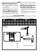
MAINTENANCE Boiler 1" Steam Equalizing Pipe 8 Pump and Low Water Control Normal Boiler Water Level 1-1/2" Cutoff Level is Arrow Mark Blowdown Valve 1" Water Equalizing Pipe 1 2 4 3 1 2 1 2 3 6 7 3 6 5 4 5-3/4 FIG. 1 REF. 5 4 4-1/2 FIG. REF.2 2-1/2 FIG. REF.3 IMMERSION HEATER FAILURE CAUSES HEATER ELEMENT CONDITION PROBABLE CAUSE 1. Water leakage at heater flange 1. Heater bolts improperly tightened. Refer to flange tightening instructions. 2.
RENEWAL PARTS IDENTIFICATION Part Description Part Number Part Description Check Valve 1/2” CES-6 through CES-18 . . . . . . . . . . . . . . . . . . Check Valve 3/4” CES-24 through CES-180 . . . . . . . . . . . . . . . . Gauge Glass Assembly Valves (O-ring gaskets included) . . . . . . . Protector Rods (2 required) CES-6 through CES-18 . . . . . . . . . Protector Rods (2 required) CES-24 through CES-72 . . . . . . . . Protector Rods (2 required) CES-100 through CES-180 . . . . . . . .
RENEWAL PARTS IDENTIFICATION Part Description Part Number VALVES & GAUGES 1/4” Ball Valve (Pressure Gauge) . . . . . . . . . . . . . . . . . . . . . . . . Blowdown Valve 1/2” CES-6 through CES-18 . . . . . . . . . . . . . . Blowdown Valve 1” CES-24 through CES-180 . . . . . . . . . . . . . . Pressure Gauge 2” 0-160 psi CES-6 through CES-72 (50 and 100 psi trim) . . . . . . . . . . . . . . . . . . . . . . . . Pressure Gauge 3 1/2” 0-160 psi CES-100 through CES-180 (50 and 100 psi trim) . . . . . . . . . .