
Owner's manual


BLOWDOWN INSTRUCTIONS
Blowdown is an essential part of generator operation. It is the
best preventive maintenance you can give your generator and
will add years of life to the unit. Make sure that a blowdown
schedule is established and followed regularly.
In extremely hard water areas, blowdown may be necessary
once a day. In other areas, once each week may be sufficient. If
there is a particular problem which applies to your local water
condition, other than mineral content, take this into consideration
in determining what schedule is to be followed.
1. At the end of the working day turn the control switch to the
OFF position and close the watter supply valve.
2. If blowing down into a receptacle, allow the pressure to
decrease to 15-20 psi before opening the blowdown valve.
3. It is preferable to connect the blowdown valve directly into a
drainage system, if local codes permit. If this is allowed, the
generator can be discharged at operating pressure.
4. When discharge is complete and the generator is drained, close
the blowdown valve and open the water supply valve, allowing
the generator to fill to normal level.
5. Close wall-mounted safety switch.
6. If you have been supplied with a manual reset control (as
required in some states), the reset button on the control must be
pushed before generator will begin developing pressure.
CAUTION: Do not push reset until boiler has filled with water.
7. WARNING: The use of chemical cleaning compounds in
these generators voids the warranty, unless approved by the
manufacturer.
OPERATION
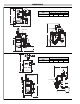
WIRING DIAGRAMS
Standard
1-3 kW, 120V
1 Ø
Diagram 1
1-3 kW, 208V-480V
1 Ø
1-3 kW, 208V-240V & 480V
3 Ø
Diagram 2 Diagram 3
Diagram 4
Diagram 6Diagram 5
Diagram 7 Diagram 8 Diagram 9
6 kW, 208V-480V, 1 Ø
9 kW, 480V, 1 Ø
9 kW, 230V-277V, 1 Ø
12-15 kW, 480V, 1 Ø
C
C
9 kW, 208V-220V, 1 Ø
12 kW, 277V, 1 Ø
40-47A
C
C
FU1
FU2
12 kW, 208V-240V, 1 Ø
15 kW, 208V-277V, 1 Ø
48A
C
C
FU1
FU2
C
C
FU3
FU4
6-15 kW, 208V-240V, 3 Ø
15 kW, 208V, 3 Ø
40A
C
FU1
C
C
FU2
FU3
From Power Circuit, Separate Source, or Transformer
C
W
B
R
Control Circuit Diagram
KEY
For All Units with Contactors
Contactor
Normally Open
Thermostat Switch
Black Lead
Red Lead
White Lead
C
B
R
W
120V 1Ph