User’s Guide 10 21 °F lox °C a rom rm Ala omega.com t oin tP Se www.omega.com e-mail: info@omega.com mp Te t Se t n i Po 0037-75429 ® ® Ch ad Lo Shop online at CN2110 Rev.
omega.com ® ® Omega OMEGAnet Online Service ® www.omega.com Internet e-mail info@omega.com Servicing North America: USA: ISO 9001 Certified Canada: One Omega Drive, P.O. Box 4047 Stamford CT 06907-0047 TEL: (203) 359-1660 e-mail: info@omega.com 976 Bergar Laval (Quebec) H7L 5A1 TEL: (514) 856-6928 e-mail: info@omega.
CN 2110 Temperature Controller Table of Contents Manual Sections Illustrations 1–Quick Setup ................................................................................................... 1 2–Introduction ................................................................................................... 2 3–Installation and Wiring .................................................................................. 4 4–Adjusting Setpoint and Configuration ................................................
Omega CN 2110
CN 2110 Temperature Controller Section 1—Quick Setup After the controller is properly wired into the system, the user only needs to verify the sensor input and control type and adjust the set point. Setting the Sensor and Control Mode Adjust the dip switches located on the bottom of the unit as shown in Figure 1.1. The factory settings are J, TC, °F, and PI. It is simpler to adjust the dip switch prior to mounting the CN 2110. K TC ˚F PI J RTD ˚C ONOF J RTD ˚C ONOF K TC ˚F PI Figure 1.
Omega Section 2—Introduction Description The CN 2110 Temperature controller offers simple setup, flexibility and control features in an attractive, compact design. The CN 2110 is housed in a rugged, plastic 1/4 DIN package that only requires four inches behind the mounting surface. Straightforward operation and easy-to-use control features are major strengths of the CN 2110 controller. Easy Three-Step Setup: The CN 2110 delivers exceptional process temperature control.
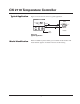
CN 2110 Temperature Controller Typical Application Figure 2.2 shows the CN 2110 in a typical application. Chromalox® 2110 Load °F Alarm °C Temp Set Point Heater Output Input Set Point Alarm Output Sensor Process Figure 2.2 Typical Application Model Identification Section 2–Introduction Before installation, please identify your controller model number. The model number appears on a label on the side of the housing.
Omega Section 3—Installation and Wiring Sensor and Control Type Selection Switches Set the CN 2110 controller’s configuration via mechanical dip switches, located on the bottom of the unit. Factory settings are J, TC, °F, and PI Control. Switches are easier to set before mounting. To change the switch settings, first disconnect all wiring and power from the unit.
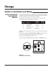
CN 2110 Temperature Controller Mounting Two mounting collars securely hold the CN 2110 controller in the mounting hole. Remove these mounting collars before installation. Removing Mounting Collars 1. To remove the rear collar, press the sides of the collar. This releases holding tabs on the top and bottom of the collar. 2. Slide the collar off the back of the unit. 3. Slide the front collar off the back of the unit Press In Front Collar Holding Tabs Rear Collar Press In Figure 3.
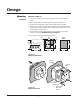
Omega Mounting continued Mount the CN 2110 1. Cut out a 1/4 DIN, 3.6-inch (92mm) square hole in the mounting panel. 2. Insert the unit into the mounting hole as shown in Figure 3.4. 3. Slide the front mounting collar onto the back of the controller. 4. Slide the rear mounting collar onto the back of the controller until the holding tabs securely engage with the holding tab slots in the controller housing (see Figure 3.4). 5.
CN 2110 Temperature Controller Good Wiring Practices Separate wire into bundles—When planning the system wiring, separate wiring into functionally similar bundles, e.g. • Power leads • Sensor leads (if power leads must cross sensor leads, they should cross at a 90° angle) • Output signal lines Separate sources of electrical noise—Locate all sources of electrical noise in your system, and separate these sources from the control system, e.g.
Omega Sensor Input Wiring Sensor Wiring Notes For safety and best controller performance, • Sensor leads (thermocouple and RTD) should not be run in the same conduit as power wiring. • Twisted pair, shielded wire is recommended for sensor connections. • False temperature readings can occur if the sensor wire is exposed to electrical noise. • Ungrounded thermocouples are recommended. • Thermocouple extension wire, if required, must be the same type as the thermocouple (i.e.
CN 2110 Temperature Controller Sensor Input Wiring continued Three-Wire RTD Inputs IMPORTANT: When making the three-wire RTD input connection, make the resistance of all three extension leadwires equal by using the same gauge and same length of wire for optimum accuracy. A three-wire RTD will generally have two wires of the same color. Connect the same colored wires to the RTDL connections. Connect the alternate colored wire to the RTDH connection.
Omega Control Output Wiring The following figures show the proper control output wiring for the various CN 2110 configurations. R1 (1 Amp Relay) and T1 (1 Amp, Solid State Relay) Output Wiring When driving a contactor coil or other inductive load, an appropriately rated AC snubber circuit is recommended (Omega Part. No. CNQUENCHARC), as shown in Figure 3.9. COM NO NC 120/240 Fuse VAC Load Neutral Snubber Figure 3.
CN 2110 Temperature Controller Control Output Wiring continued T5 (Solid State Relay, 5 Amps) and T10 (Solid State Relay, 10 Amps) Output Wiring Note: CN 2110 model T10 has a fan. CN 2110 model T5 does not have a fan. Fan COM Fuse Load NO NC 120/240 VAC Neutral Figure 3.12 Control Output Wiring–T5 and T10 Instrument Power Wiring Make 120 or 240 VAC instrument power connections to terminals as shown in Figure 3.13. 120/240VAC Neutral Ground NO COM NC Figure 3.
Omega Section 4—Adjusting Set Point and Configuration Adjusting the Set Point 1. Set selection switches (see Figure 3.1). 2. Apply power to the unit. 3. To adjust the set point on the CN 2110 Temperature Controller, press and hold the Set Point button (see Figure 4.1). The Set Point light is illuminated and the set point value is displayed. 4. While still pressing the Set Point button, press either the or button to adjust the set point to the desired value (see Figure 4.2). 5. Release the Set Point button.
CN 2110 Temperature Controller Configuration continued 4. Press the or buttons to adjust the value (only the value is displayed during adjustment). See Figure 4.7. The new value is set when the or button is released. ) button and press the button to 5. Press and hold the Set Point ( advance to the next menu. See Figure 4.8. (Holding the Set Point ( ) button and pressing the button moves through menus in the opposite direction.) Repeat steps 4 and 5 through the configuration menus.
Omega Security Codes and Levels Configuration Menus To limit access to the user configuration interface, security codes are assigned to different menu levels. Make security codes available to operators, maintenance crew, supervisors, etc. according to what function level you want for each group. Security Level C is not recommended for most users. Gain access to configuration menus using the following codes.
CN 2110 Temperature Controller Configuration Menus continued Menu Code Function Cycle Time Adjustable Range Factory Default Security Level .1 to 60.0 Sec. Output R1, R20 = 30 sec. T1, T5, T10 DC = 1 sec. B The time for the output to complete ON to OFF to ON cycle. Used only with proportional control. A fast cycle time provides better control, but can cause premature wear to contactor or other power switching devices. Magnetic contactors should not be switched at less than a 30 second cycle time.
Omega Section 5—Control and Alarm Operation Control Operation The CN 2110 is shipped from the factory with PI (proportional/integral) control. Proportional control actually determines the percent of heat needed to control the process. The factory setting for the Proportional Band is 25°F and the Automatic Reset (Integral) is set at 0.1 repeats/ minute. These settings will control many processes without any changes to the controller.
CN 2110 Temperature Controller Section 6—Replacing Output Modules The CN 2110 Temperature Controller was shipped with the output modules installed as ordered. The 10A Solid State Relay and 20A Mechanical Relay output cards control small cartridge heater or strip heater loads directly, eliminating the need for a remote contactor or solid state relay. If a larger load is required, the CN 2110 can be configured with a 1A Pilot Duty Relay or Solid State Relay Drive.
Omega Module Installation continued ! 3. Remove the back cover by lifting four housing clips on the controller. This releases the back cover. Then pull cover straight off the controller. 4. Gently pry around the sides to loosen and remove the module. Pull module straight out to avoid bending pin connections. WARNING: Do not remove module by the handling components on the module board. This could damage the module.
CN 2110 Temperature Controller Section 7—Calibration Calibration Offset Calibration offset offsets the displayed value. Usually, this option is used to match displays of two different instruments that are measuring the same temperature, but are displaying different temperatures due to different thermocouple accuracy or placement of the thermocouples. Caution is advised when adding an offset to the display, since the actual sensed temperature will not be displayed.
Omega Calibration continued Calibration Notes: When calibrating the CN 2110 1. You must have a sensor simulator to calibrate the CN 2110 controller. Substitute a precision sensor simulator (Thermocouple simulator or resistance simulator box) for sensor inputs. 2. Disconnect load power to prevent damage to the process or load. 3. Calibrate RTD inputs using copper (Cu) wire. Calibrate thermocouple inputs using thermocouple extension wire of the same type as the thermocouple you are calibrating. 4.
CN 2110 Temperature Controller Section 8—Specifications Control Modes ..................................... Control Adjustments Proportional Band .......................... Automatic Reset ............................ Cycle Time .................................... On/Off Deadband .......................... Set Point Upper Limit .................... Set Point Lower Limit ................... Output Limit .................................. Alarm Adjustments Type ...............................................
Omega Section 9—Troubleshooting The following Troubleshooting Guide offers simple solutions to common problems and explains the CN 2110’s Error Messages. Review this section for a possible solution to your problem before contacting Omega. Note: For each symptom, perform correction steps in the order listed. CN 2110 Symptom Probable Cause Correction Steps Power applied, display does not light, and controller does not function 1. No power applied 2. External fuse open 1.
CN 2110 Temperature Controller Troubleshooting continued Section 9–Troubleshooting Symptom Probable Cause Correction Steps Process not in control 1. Incorrect settings 2. Thermocouple Wiring 1. Check Proportional Band setting and Automatic Reset setting 2. Check thermocouple polarity Instrument continually goes through power-up reset 1. Severe electrical noise 1. Separate sensor wiring from other wiring 2. Apply power line filter 3.
Omega CN 2110
CN 2110 Temperature Controller CN 2110
MADE IN USA WARRANTY/DISCLAIMER OMEGA ENGINEERING, INC. warrants this unit to be free of defects in materials and workmanship for a period of 13 months from date of purchase. OMEGA’s WARRANTY adds an additional one (1) month grace period to the normal one (1) year product warranty to cover handling and shipping time. This ensures that OMEGA’s customers receive maximum coverage on each product. If the unit malfunctions, it must be returned to the factory for evaluation.
Omega Where Do I Find Everything I Need for Process Measurement and Control? OMEGA…Of Course! Shop online at www.omega.