
Air Conditioner User Manual
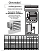

WARNING
Failure to understand and follow these installation instructions
and the WARNING notes contained therein may result in severe
personal injury, death or substantial property damage.
1. To reduce the risk of ignition of hazardous atmospheres:
In accordance with the National Electrical Code, do not install
where operating temperature code exceeds the ignition tempera-
ture of the hazardous atmosphere. Use only in atmospheres hav-
ing an ignition temperature higher than 165˚ C (329˚ F).
2. Disconnect from supply circuit before opening enclosures.
3. Hazard of Electric Shock. Heater must be effectively grounded in
accordance with N.E.C. to eliminate shock hazard.
4. Heat exchanger contains Propylene Glycol under pressure at oper-
ating temperature. A material safety data sheet (MSDS) is avail-
able from Chromalox upon request. Should leakage occur,
remove unit from service and investigate cause.
5. Keep all electrical enclosure covers tightly closed and secured
with all bolts and threads. Cover joints must be clean before
replacing covers.
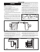
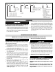
6. Install and operate in upright position only. Refer to Figure 3 for
level requirements. Failure to comply will cause overheating of
the element and shutting down the unit by tripping the high tem-
perature cutout.
7. All unused threaded openings not used for supply wiring must be
fitted with threaded plugs approved for use in hazardous loca-
tions.
8. All unit electrical installation fittings, conduit, wiring and seals
must meet NEC and local codes for hazardous locations.
9. External line fusing or circuit breaker protection is required.
10. Hi limit cutouts must never be bypassed in the control circuit.
11. Alarm pilot lamp, if supplied, will turn on if the high limit control
actuates. Steady on lamp indicates manual reset protector has
tripped. This could result if the heat exchanger is obstructed
(dirty), inlet air restricted or fan not turning. Shut off power to
unit and refer to repair procedures section of instruction sheet.
12. Mounting clearances on nameplate must be observed.
13. Use copper wire for supply connections according to size and rat-
ing on nameplate.
14. Do not install any type of gasket material on any of the electrical
junction box cover surfaces.
15. Do not attempt to override louver stops or operate unit with lou-
vers fully closed.
2
GENERAL
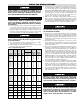
The CXH-A series units rated 3 through 35 kW are designed
for operation in Class I, Div. 1, Groups C & D and Class II, Div.
1, Groups E, F and G hazardous atmospheres having an ignition
temperature of 165˚C (329˚F) or higher. They are designed for
comfort heating and should not be operated in ambient tempera-
tures exceeding 40˚C (104˚F). All units in Table A are UL listed.
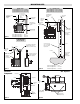
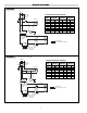
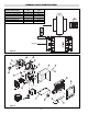
The units are easily adapted for wall, ceiling or pole mounting.
Refer to Figure 4 on Page 3 for mounting information. They are
supplied with either 24 or 120V internal control circuit voltage.
The heater is designed for use with an external hazardous location
thermostat or optional built-in thermostat.
The standard heater is designed to operate up to 7500
feet (2,286m) altitude. Consult factory for specific recommen-
dations when using the units at higher altitudes.
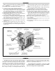
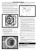
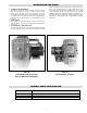
Heavy gauge adjustable
louver with minimum
opening stops - to direct air flow
Removable front cover
for ease of cleaning
High efficiency heat
exchanger with integral
aluminum-finned steel tubes
Optional service light to
indicate when unit
needs servicing
Built-in 120V control
circuit transformer
(Optional 24V available)
Heavy duty immersion heater assembly
with manual reset limit control and
NEMA 7 and 9 terminal enclosure
Protective housing
for immersion heater
terminal enclosure
Convenient terminal
block for room
thermostat connection
Motor connections
wiring access
Explosion-proof
(NEMA 7 and 9)
controls enclosure
Integral, heavy duty
magnetic contactor
Explosion
proof motor
Mounting bolt
hanger connections
Polyester powder-coated
heavy gauge steel corrosion
resistant cabinet
Overpressure
protection device