
Air Conditioner User Manual

5
WIRING AND WIRING DIAGRAMS
ELECTRIC SHOCK HAZARD. Disconnect all power
before installing or servicing heater. Failure to do so
could result in personal injury or property damage.
Heater must be installed by a qualified person in accor-
dance with the National Electrical Code, NFPA 70.
ELECTRIC SHOCK HAZARD. Any installation involving
electric heaters must be performed by a qualified
person and must be effectively grounded in accor-
dance with the National Electrical Code to eliminate
shock hazard.
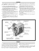
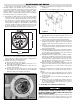
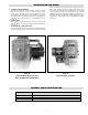
1. Loosen and remove bolts securing the main terminal enclosure
cover on side of unit. Connect heater to line supply wires at the
box lugs located on the contactor according the voltage and fre-
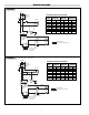
quency specified on the nameplate (see Figure 9). Refer to the
appropriate wiring diagram which also appears on the inside
cover of this enclosure (see Table B and diagrams on page 6).
EXPLOSION HAZARD. Cover joints must be clean
before replacing cover. Do not use any gasket materi-
al on joint surfaces.
2. Use copper conductors only for supply wires. Refer to name-
plate and Table B for size and rating required.
3. Connect supply line ground conductor to the box lug provided
on the base plate below contactor input lugs.
4. The fan motor is factory wired at the same voltage, and phase as
the heating elements. All motors are thermally protected and con-
nected to the main supply contactor. On three phase units, it is
necessary to verify that the fan rotation is correct. Air stream
discharge must be out front of unit. After connecting unit to line
and closing all covers tightly, energize unit momentarily. If air
does not exit front louvers, reverse any two supply leads at the
box lugs on the contactor or at the supply disconnect.
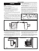
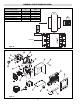
5. Either of two 1 NPT rigid conduit openings with integral stops
may be used for connection to supply line. (See Figure 9 and 10
for locations) Use only NEC approval hazardous locations means
of wiring such as mineral insulated cable and fittings or rigid con-
duit and seal fittings located as required by installation codes.
EXPLOSION HAZARD. All unused conduit openings
must be fitted with plugs that are U.L. recognized for
use in hazardous locations.
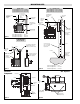
6. Heaters may be provided with a built-in control switch and/or
thermostat. If not, they should be controlled by an externally
mounted disconnect switch and/or separately mounted thermostat
as shown in the appropriate wiring diagram on page 6. In case of
malfunction, the personnel in the area should be aware of location
of heater disconnect.
7. Installation must include appropriate over current protection
devices (fusing or circuit breakers) as required by the National
Electric Code in the supply line to the unit. Refer to nameplate for
proper current ratings.
8. To operate heaters from an externally mounted hazardous location
thermostat, a terminal block is provided for connection (Figures 9
and 10). Remove the factory installed jumper across T2 and T3 on
the terminal strip. Wire the thermostat contact leads to these ter-
minals. The built in control transformer supplies the unit with
either 24V or 120V for internal unit operation. This voltage will
appear across the thermostat contacts when they are open. The
minimum thermostat contact rating should be 1 amp @ 120 VAC.
Refer to nameplate for control voltage of unit. The 1/2 NPT con-
duit wiring entry on top of the terminal enclosure should be used
to wire the thermostat to the heater (Figure 10).
9. Protection against overheating is provided by a manual reset limit
control located within the heat exchanger wiring compartment.
(Figure 9) Activation of the control will open the control circuit
and energize the pilot lamp (if supplied). If normal airflow is
restricted, or stopped, the unit will be cycled off by the manual
reset cutout. The manual reset limit control is also designed to
shut down the unit completely if the fluid level is low or other
heater malfunction occurs.
Manual reset limit control must never be bypassed in
the control circuit. If the limit actuates, shut down
unit and investigate cause of abnormal operation. Do
not reenergize until the problem has been corrected.
Users should install adequate back-up controls and
safety devices with their electric heating equipment.
If the back-up controls are to be located in the haz-
ardous area, they must be approved for use in the
class of location. Where the consequences of failure
may be severe, back-up controls are essential.
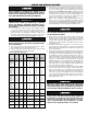
Supply Wire
90˚C Size Max Fuse Wiring
Model kW Phase Volts (ga) Amps Diagram #
CXH-A-03 3 1 208 10 25 I
CXH-A-03 3 3 208 12 15 II
CXH-A-03 3 1 240 10 20 I
CXH-A-03 3 3 240 12 15 II
CXH-A-03 3 3 480 12 15 II
CXH-A-03 3 3 575 12 15 II
CXH-A-05 5 1 208 8 35 I
CXH-A-05 5 3 208 10 20 II
CXH-A-05 5 1 240 8 30 I
CXH-A-05 5 3 240 10 20 II
CXH-A-05 5 3 480 12 15 II
CXH-A-05 5 3 575 12 15 II
CXH-A-07 7.5 1 208 6 50 I
CXH-A-07 7.5 3 208 8 30 II
CXH-A-07 7.5 1 240 6 45 I
CXH-A-07 7.5 3 240 8 25 II
CXH-A-07 7.5 3 480 12 15 II
CXH-A-07 7.5 3 575 12 15 II
CXH-A-10 10 3 208 8 40 II
CXH-A-10 10 1 240 4 60 I
CXH-A-10 10 3 240 8 35 II
CXH-A-10 10 3 480 10 20 II
CXH-A-10 10 3 575 12 15 II
CXH-A-15 15 3 208 4 60 II
CXH-A-15 15 3 240 6 50 II
CXH-A-15 15 3 480 8 25 II
CXH-A-15 15 3 575 10 20 II
CXH-A-18 18 3 240 4 60 II
CXH-A-20 20 3 480 8 35 II
CXH-A-20 20 3 575 8 30 II
CXH-A-25 25 3 480 8 40 II
CXH-A-25 25 3 575 8 35 II
CXH-A-30 30 3 480 6 50 II
CXH-A-30 30 3 575 8 40 II
CXH-A-35 35 3 480 4 60 II
CXH-A-35 35 3 575 6 50 II
Table B – Supply Wiring Requirements