
Air Conditioner User Manual

MAINTENANCE AND REPAIR
The occurrence of the manual reset limit control to trip is an
abnormal condition. Care should be taken to determine the exact
reason that the high limit control tripped. Possible problem areas
could be dirty heat exchanger, blocked air inlet or outlet,
fan/motor malfunction, too high operating ambient, incorrect
operating voltage, or leaking heat exchanger. In the event that the
heat exchanger is defective, it must be replaced.
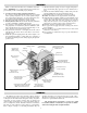
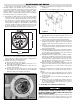
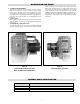
1. The manual reset limit control is located in the heating element
hazardous location enclosure on the heat exchanger which is
covered by the sheet metal housing attached to the side of the
unit. To gain access, remove the four sheet metal screws holding
the sheet metal cover in place and unthread the cast alu
minum
enclosure lid. (See Figure 11.) The manual reset limit control
device has a small reset button protruding from the center of its
back housing. Depress this button in to reset the control.
Replace the aluminum enclosure lid and sheet metal cover.
III. FAN MOTOR AND BLADE
1. The motor is a sealed unit that requires no lubrication. If the
motor is defective, it must be replaced with an original factory
supplied motor. (See renewal parts section.)
2. To replace the motor, proceed as follows:
A. Disconnect the unit from power supply.
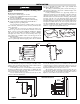
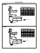
B. (Units with motor splice box) Remove 4 bolts and cover of
motor splice box (See Figure 12).
C. (Units without motor splice box) Remove 16 bolts and cover
of main control enclosure.
D. Note wire connections for future reference and disconnect all
wires leading to the motor. All motor wires are permanently
marked according to the nameplate on the motor.
E. Remove 4 bolts in motor base holding it to rear cabinet shelf.
See Figure 13.
F. Remove 4 screws holding fan guard to cabinet.
G. Unthread union at motor wiring outlet nipple connection.
Carefully lift the motor, fan blade, and guard off of the cabi-
net.
H. Note position of fan blade on motor shaft. Loosen the two set
screws to remove the fan blade and key from shaft motor.
I. Place guard and fan blade on replacement motor shaft in same
locations as original motor. Align key ways in hub and shaft.
Insert key flush with fan hub and tighten the two hub set
screws.
J. Feed motor wires back into conduit and reposition motor back
on unit. Center fan blade in opening and rotate to be sure that
it clears housing and guard.
K. Thread motor nipple connection into conduit union and tight-
en (5 threads minimum). Replace bolts in motor base and reat-
tach fan guard to back of housing in four places. Recheck
blade rotation and tighten all hardware.
L. Trim all motor leads extending out of the conduit to 6 lengths.
Strip off 3/8 of insulation at cut ends. Using the motor name-
plate, previous notes, and marked wires, reconnect the motor
for the unit voltage rating as indicated on the heater name-
plate. Re-attach the ground wire to the connection inside the
enclosure. Replace cover and tighten securely.
M. Check fan rotation by momentarily energizing the unit. Air
must exit at cabinet front. Reverse any 2 leads at contactor or
line supply disconnect to reverse rotation of three phase
motor.
3. Removal of fan blade does not require that the motor wiring be
disturbed. To clean, service or change the fan blade proceed as
follows:
A. Remove the four carriage bolts holding the motor base in
place on the cabinet platform. Mark the platform to reposition
at same location.
B. Loosen the four screws on the cabinet back holding the fan
guard in place.
C. Pull the motor to the rear extending the conduit connection at
the electrical enclosure. Fan blade and hub set screws can now
be accessed by tilting the guard rearward at top or bottom
back over the motor shell.
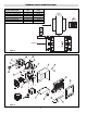
IV. ELECTRICAL COMPONENT SERVICING
EXPLOSION/ELECTRIC SHOCK HAZARD. Disconnect
all power before opening enclosure covers or servic-
ing heater. Failure to comply could result in personal
injury or property damage.
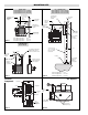
When provided, the following components are located in the cast
aluminum hazardous location enclosure. Remove cover and
retaining bolts to gain access the following items (See Figure 16):
8
Figure 12
Figure 13
5-3/4"
5-3/4"
Figure 11