
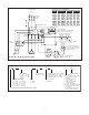
Specifications


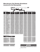

13
Maintenance and Repair
The occurrence of the manual reset limit control to trip is
an abnormal condition. Care should be taken to determine
the exact reason that the high limit control tripped. Possible
problem areas could be dirty heat exchanger, blocked air in-
let or outlet, fan/motor malfunction, too high operating ambi-
ent, incorrect operating voltage, or leaking heat exchanger.
In the event that the heat exchanger is defective, it must be
replaced.
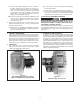
1. The manual reset limit control is located in the heating
element hazardous location enclosure on the heat ex-
changer which is covered by the sheet metal housing at-
tached to the side of the unit. To gain access, remove the
four sheet metal screws holding the sheet metal cover in
place and unthread the cast aluminum enclosure lid. (See
Figure 11.) The manual reset limit control device has a
small reset button protruding from the center of its back
housing. Depress this button in to reset the control. Re-
place the aluminum enclosure lid and sheet metal cover.
5-3/4"
5-3/4"
Figure 11
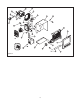
III. FAN MOTOR AND BLADE
1. The motor is a sealed unit that requires no lubrication. If
the motor is defective, it must be replaced with an origi-
nal factory supplied motor. (See renewal parts section.)
2. To replace the motor, proceed as follows:
A. Disconnect the unit from power supply.
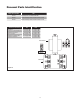
B. (Units with motor splice box) Remove 4 bolts and cov-
er of motor splice box (See Figure 12).
C. (Units without motor splice box) Remove 16 bolts and
cover of main control enclosure.
D. Note wire connections for future reference and dis-
connect all wires leading to the motor. All motor wires
are permanently marked according to the nameplate
on the motor.
E. Remove 4 bolts in motor base holding it to rear cabi-
net shelf. See Figure 13.
F. Remove 4 screws holding fan guard to cabinet.
Figure 12
Figure 13
G. Unthread union at motor wiring outlet nipple connec-
tion. Carefully lift the motor, fan blade, and guard off of
the cabinet.
H. Note position of fan blade on motor shaft. Loosen the
two set screws to remove the fan blade and key from
shaft motor.
I. Place guard and fan blade on replacement motor shaft
in same locations as original motor. Align key ways in
hub and shaft. Insert key flush with fan hub and tighten
the two hub set screws.
J. Feed motor wires back into conduit and reposition
motor back on unit. Center fan blade in opening and
rotate to be sure that it clears housing and guard.
K. Thread motor nipple connection into conduit union
and tighten (5 threads minimum). Replace bolts in mo-
tor base and reattach fan guard to back of housing
in four places. Recheck blade rotation and tighten all
hardware.