
Blower User Manual


5
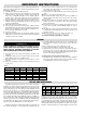
WIRING DIAGRAMS
SDRA 30kW, 480V, 3PH
SDRA 48kW, 480V, 3PH
SDRA 60kW, 480V, 3PH
Attach all Wires on this
Side of Contactor to
Auxillary Terminals
Blk/Red
or Grey
Blk
Transformer
Control Enclosure
Blk
Wht
Run these Wires
Through 1" Conduit
Contactor
Motor Relay
Toggle Switch
L1
L2
L3
Motor
P4
P5
P6
T3
T1
T2
T9
T8
T7
T4
T6
T5
Inlet
Thermostat
Outlet
Thermostat
Cutout
12
1
Front of
Heater
10
Heater Terminal Box
4
Motor
Relay
Control Enclosure
45 Amp
Fusing
30 Amp Fusing
L1
L3
L2
Wht
Transformer
Contactor
Contactor
Blk
Toggle
Switch
Amber Pilot Light
Green Pilot Light
Run these Wires
Through 1/2"
Conduit
Motor
P4
P5
P6
T3
T1
T2
T9
T8
T4
T6
T5
T7
Inlet Thermostat
Outlet Thermostat
Cutout
1
14
1
17
18
15
13
12
Front
of
Heate
r
Heater Terminal Box
4
10
Run these Wires
through 1/4" Conduit
One end attached
to screw in terminal box
and other end attached to
screw on sub panel.
Motor
Relay
Control Enclosure
50 Amp Fusing
50 Amp Fusing
L1
L3
L2
Wht
Transformer
Contactor
Contactor
Blk
Toggle
Switch
Amber Pilot Light
Green Pilot Light
Run these Wires
Through 1/2"
Conduit
Motor
P4
P5
P6
Inlet Thermostat
Outlet Thermostat
Cutout
14
1
17
15
13
12
Heater Terminal Box
4
10
Run these Wires
through 1/4" Conduit
One end attached
to screw in terminal box
and other end attached to
screw on sub panel.
T3
T1
T2
T9
T8
T4
T6
T5
T7
1
1
18
22
20
2
24
23
Front
of
Heate
r