
Warranty


CHRONOMITE INSTANT-FLOW WATER HEATER
INSTALLATION AND OPERATION INSTRUCTIONS - (LOW FLOW MODELS)
(Before installation, compare electrical needed for the model of heater selected)
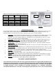
TABLE 1
Instant-Flow
Specifications:
• Dimensions: 6¼” x 9 5/8” x 2 ¾”
• Weight: 5 lbs.
• Materials: Rugged cast aluminum alloy casing, Celcon waterways, nichrome parts
• Color: White (unless stainless steel housing)
• Pipe Fittings: Female ¼” NPT standard pipe thread
• Pressure Requirements: 25 PSI Minimum, 150 PSI Maximum (300 PSI tested) No pressure relief valve needed
unless required by local codes.
• Maximum Operating Temp: 140°F
• Flow Switch Activation: .4 GPM
• Flow Switch De-Activation: .35 GPM
• Listings: UL, HUD, IAPMO
THE MANUFACTURER OF THIS WATER HEATER WILL NOT BE LIABLE FOR ANY DAMAGES
DUE TO THE FAILURE TO FOLLOW THESE INSTALLATION AND OPERATION INSTRUCTIONS.
CAUTION: BEFORE BEGINNING THE INSTALLATION:
A) Turn off the circuit breaker to avoid dangerous electrical shocks.
B) Turn off the water supply.
1. Remove electrical access cover. Attach conduit to the conduit access hole. Then feed wires. Do not attach wiring.
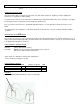
2. Mount unit horizontally against the wall so the silver label reads correctly (See Fig. 1). Mount with four screws
through the flanges located on each corner using molly anchors or fasteners.
CAUTION: Heating elements may burn out if unit is not mounted horizontally.
3. Connect plumbing. Use ¼” tapered national pipe thread at cold water inlet and hot water outlet (See Fig. 1). Use
compression fittings supplied for ease of installation. Do not apply heat to these fittings.
4. Run water through the unit to expel all air bubbles. Check for leaks at all fitting joints.
5. Connect wiring. Attach ground wire to center terminal and hot wires to outer terminals (See Fig. 3)
6. Replace electrical access cover. Turn on the circuit breaker. The unit is now ready for use.
7. Local plumbing and electrical codes must be followed in the installation of this water heater and it’s accessories.
8. Failure to comply with code requirements voids the warranty.
9. Failure to install faucet flow control as shown on Fig. 2 will cause unsatisfactory operation of the heater.
Model No. Wattage Voltage Breaker
Size
SR-15L 1800 110/120 15A
SR-15L 4150 277 15A
SR-20L 2400 110/120 20A
SR-20L 4160 208 20A
SR-20L 4800 220/240 20A
SR-20L 5540 277 20A
SR-30L 3600 110/120 30A