SECTION TABLE OF CONTENTS PAGE 1 INTRODUCTION . . . . . . . . . . . . . . . . . . . . . . . . . . . . . . . . . . . . . . . . . . . . . . . . . . . . . . . . . . . . . 3 1 2 THINGS TO KNOW BEFORE STARTING YOUR VEHICLE . . . . . . . . . . . . . . . . . . . . . . . . . . . 7 2 3 UNDERSTANDING THE FEATURES OF YOUR VEHICLE . . . . . . . . . . . . . . . . . . . . . . . . . . . . 47 3 4 UNDERSTANDING YOUR INSTRUMENT PANEL . . . . . . . . . . . . . . . . . . . . . . . . . . . . . . . . . .
INTRODUCTION CONTENTS 䡵 Introduction . . . . . . . . . . . . . . . . . . . . . . . . . . . 4 䡵 Vehicle Identification Number . . . . . . . . . . . . . . 6 䡵 How To Use This Manual . . . . . . . . . . . . . . . . . 4 䡵 Vehicle Modifications / Alterations . . . . . . . . . . 6 䡵 Warnings And Cautions . . . . . . . . . . . . . . . . . .
INTRODUCTION INTRODUCTION This manual has been prepared with the assistance of service and engineering specialists to acquaint you with the operation and maintenance of your new vehicle. It is supplemented by a Warranty Information Booklet and various customer oriented documents. You are urged to read these publications carefully. Following the instructions and recommendations in this manual will help assure safe and enjoyable operation of your vehicle.
INTRODUCTION 5 1
INTRODUCTION WARNINGS AND CAUTIONS This manual contains WARNINGS against operating procedures which could result in an accident or bodily injury. It also contains CAUTIONS against procedures which could result in damage to your vehicle. If you do not read this entire manual you may miss important information. Observe all Warnings and Cautions.
THINGS TO KNOW BEFORE STARTING YOUR VEHICLE 2 CONTENTS 䡵 A Word About Your Keys . . . . . . . . . . . . . . . . . 9 ▫ Central Locking—If Equipped . . . . . . . . . . . . .14 ▫ Ignition Key Removal . . . . . . . . . . . . . . . . . . . 9 ▫ Door Ajar Warning . . . . . . . . . . . . . . . . . . . . .14 ▫ Automatic Transaxle Ignition Interlock System . .10 ▫ Automatic (Rolling) Door Locks . . . . . . . . . . . .14 ▫ Key-In-Ignition Reminder . . . . . . . . . . . . . . . .
THINGS TO KNOW BEFORE STARTING YOUR VEHICLE ▫ General Information . . . . . . . . . . . . . . . . . . . .18 ▫ Transmitter Battery Service . . . . . . . . . . . . . . .19 䡵 Vehicle Theft Alarm . . . . . . . . . . . . . . . . . . . . .19 ▫ Tamper Alert . . . . . . . . . . . . . . . . . . . . . . . . .20 ▫ Security System Manual Override . . . . . . . . . . .20 䡵 Trunk Lock And Release . . . . . . . . . . . . . . . . . .21 䡵 Trunk Safety Warning . . . . . . . . . . . . . . . . . . . .
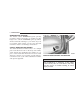
THINGS TO KNOW BEFORE STARTING YOUR VEHICLE A WORD ABOUT YOUR KEYS 9 Ignition Key Removal CAUTION! 2 An unlocked car is an invitation to thieves. Always remove the key from the ignition, lock the doors, and close the windows when leaving the vehicle unattended. Ignition Key Positions Place the shift lever in PARK and make sure that the gearshift knob push button has returned to the out position. Turn the key to the Lock position and remove the key.
THINGS TO KNOW BEFORE STARTING YOUR VEHICLE NOTE: If you try to remove the key before you place the lever in PARK, the key may become trapped temporarily in the key cylinder. If this occurs, rotate the key clockwise slightly, then remove the key as described. If a malfunction occurs, the system may trap the key in the ignition cylinder to warn you that this safety feature is inoperable. The engine can be started and stopped but the key cannot be removed until you obtain service.
THINGS TO KNOW BEFORE STARTING YOUR VEHICLE • Additional Sentry Keys or Mobil Speed Pass™ devices held too close to the ignition key when starting the vehicle may cause problems when attempting to start the vehicle. These devices cannot damage the Sentry Key System, but can cause a momentary problem when attempting to start the engine. If a problem occurs, remove the Sentry Key from the key ring and restart the vehicle. Pagers, cell phones, walkmans, etc., have no effect on this system.
THINGS TO KNOW BEFORE STARTING YOUR VEHICLE Turn the ignition Off and remove the first key. 2. Insert the second valid key and switch the ignition On within 15 seconds. After ten seconds a chime will sound and the Theft Alarm Light will begin to flash. Turn the ignition Off and remove the second key. 3. Insert a blank Sentry Key into the ignition and switch the ignition On within 60 seconds. After 10 seconds a single chime will sound.
THINGS TO KNOW BEFORE STARTING YOUR VEHICLE 13 WARNING! When leaving the vehicle always remove the key from the ignition lock, and lock your vehicle. Do not leave children unattended in the vehicle, or with access to an unlocked vehicle. Unsupervised use of vehicle equipment may cause severe personal injuries and death. Power Door Locks There is a door lock switch on each front door located to the front of each door handle. Press this switch to lock or unlock the doors.
THINGS TO KNOW BEFORE STARTING YOUR VEHICLE If you press the door lock switch while the keys are in the ignition switch, and the driver’s door is open, the doors will not lock. Central Locking—If Equipped Turning the driver’s door lock to the unlock position twice within five seconds will unlock both doors. Turning the key in the driver’s door to the unlock position once will unlock only the driver’s door. Locking the driver’s door with the key will lock both doors.
THINGS TO KNOW BEFORE STARTING YOUR VEHICLE 15 The Automatic Door Locks can be disabled or re-enabled by performing the following procedure: 1. Close all doors and place the key in the ignition. 2 2. Cycle the ignition switch between OFF and ON/RUN and back to OFF 4 times ending up in the OFF position. Power Door Lock Switch 4. A single chime will indicate the completion of the programming. Ignition Key Positions 3. Depress the power door lock switch to lock the doors.
THINGS TO KNOW BEFORE STARTING YOUR VEHICLE 1. Close all doors and place the key in the ignition. 2. Cycle the ignition switch between OFF and ON/RUN and back to OFF 4 times ending up in the OFF position. 3. Depress the power door lock switch to unlock the doors. 4. A single chime will indicate the completion of the programming. REMOTE KEYLESS ENTRY — IF EQUIPPED This system allows you to lock or unlock the doors or open the trunk from distances up to 23 feet (7 meters) using a transmitter.
THINGS TO KNOW BEFORE STARTING YOUR VEHICLE 1. Press and hold the Lock button on the transmitter. 2. Continue to hold the Lock button, wait at least 4 but no longer than 10 seconds, then press the Trunk button. 3. Release both buttons. To lock the doors: The horn will chirp and the headlamps will flash once to acknowledge the lock signal. NOTE: To enable or disable the Lamp Flash, see the Note just prior to the sub-section “To lock the doors”.
THINGS TO KNOW BEFORE STARTING YOUR VEHICLE To use the Panic Alarm: Press and hold the Panic Button for at least 1 second to activate the panic alarm. Press and hold the panic button a second time or unlock the door with the key (if equipped with central locking) to deactivate the alarm. The alarm will also shut itself off after 3 minutes, or when the vehicle speed reaches 15 MPH (24 km/h). To Program Additional Transmitters: Up to 4 transmitters can be programmed to your vehicle.
THINGS TO KNOW BEFORE STARTING YOUR VEHICLE 2. Closeness to a radio transmitter such as a radio station tower, airport transmitter, and some mobile or CB radios. Transmitter Battery Service The recommended replacement batteries are CR2016. 1. Pry the transmitter halves apart with a dime or similar object. Make sure not to damage the rubber gasket material during removal. 19 2. Remove and replace the batteries. Avoid touching the new batteries with your fingers. Skin oils may cause battery deterioration.
THINGS TO KNOW BEFORE STARTING YOUR VEHICLE To set the alarm: 1. Remove the keys from the ignition switch and get out of the vehicle. 2. Lock the door using either the power door lock switch, the key, or the Keyless Entry Transmitter and close all doors. 3. The light in the instrument cluster will flash rapidly for 15 seconds. This shows that the system is arming. If the light comes on but does not flash, the system is still armed, but there is a problem in the trunk circuit.
THINGS TO KNOW BEFORE STARTING YOUR VEHICLE TRUNK LOCK AND RELEASE 21 With the ignition ON, the word “deck” will be displayed in place of the odometer display indicating that the trunk is open. The odometer display will reappear once the trunk is closed or if the trip button is depressed. With the key in lock position or key out, the “deck” will be displayed until the trunk is closed.
THINGS TO KNOW BEFORE STARTING YOUR VEHICLE Trunk Internal Emergency Release WINDOWS Power Windows Emergency Release NOTE: As a security measure, a Trunk Internal Emergency Release lever is built into the trunk latching mechanism. In the event of an individual being locked inside the trunk, the trunk can be simply opened by pulling on the glow-in-the-dark handle attached to the trunk latching mechanism. See picture.
THINGS TO KNOW BEFORE STARTING YOUR VEHICLE The window controls on the driver’s door operate all windows. The driver’s window switch has an Auto Down feature. Press the window switch past the detent, release, and the window will go down automatically. To open the window part way, pull the window switch part way and release it when you want the window to stop. Wind Buffeting Wind buffeting can be described as the perception of pressure on the ears or a helicopter type sound in the ears.
THINGS TO KNOW BEFORE STARTING YOUR VEHICLE Buckle up even though you are an excellent driver, even on short trips. Someone on the road may be a poor driver and cause a collision which includes you. This can happen far away from home or on your own street. Research has shown that seat belts save lives, and they can reduce the seriousness of injuries in a collision. Some of the worst injuries happen when people are thrown from the vehicle.
THINGS TO KNOW BEFORE STARTING YOUR VEHICLE Lap/Shoulder Belt Operating Instructions 1. Enter the vehicle and close the door. Sit back and adjust the front seat. Latch Plate 25 2. The seat belt latch plate is on the back of your seat. Grasp the latch plate and pull out the belt. Slide the latch plate up the webbing as far as necessary to allow the belt go around your lap. Latch Plate To Buckle 3. When the belt is long enough to fit, insert the latch plate into the buckle until you hear a ”click.
THINGS TO KNOW BEFORE STARTING YOUR VEHICLE WARNING! • A belt that is buckled into the wrong buckle will not protect you properly. The lap portion could ride too high on your body, possibly causing internal injuries. Always buckle your belt into the buckle nearest you. • A belt that is too loose will not protect you as well. In a sudden stop you could move too far forward, increasing the possibility of injury. Wear your seat belt snugly. • A belt that is worn under your arm is very dangerous.
THINGS TO KNOW BEFORE STARTING YOUR VEHICLE 27 WARNING! WARNING! • A lap belt worn too high can increase the risk of internal injury in a collision. The belt forces won’t be at the strong hip and pelvic bones, but across your abdomen. Always wear the lap belt as low as possible and keep it snug. • A twisted belt can’t do its job as well. In a collision it could even cut into you. Be sure the belt is straight. If you can’t straighten a belt in your vehicle, take it to your dealer and have it fixed.
THINGS TO KNOW BEFORE STARTING YOUR VEHICLE The pretensioners are triggered by the front airbag control module (see Airbag Section). Like the front airbags, the pretensioners are single use items. After a collision that is severe enough to deploy the airbags and pretensioners, both must be replaced.
THINGS TO KNOW BEFORE STARTING YOUR VEHICLE 4. Turn off the engine. A single chime will sound to signify that you have successfully completed the programming. The Enhanced Warning System (BeltAlert) can be reactivated by repeating this procedure. NOTE: Although the Enhanced Warning System (BeltAlert) has been deactivated, the Seat Belt Warning Light will continue to illuminate while the driver’s seat belt remains unbuckled.
THINGS TO KNOW BEFORE STARTING YOUR VEHICLE Driver and Right Front Passenger Supplemental Restraint System (SRS) - Airbag NOTE: These airbags are certified to the new Federal regulations that allow less forceful airbags. WARNING! Front Airbag Components This vehicle has front airbags for both the driver and front passenger as a supplement to the seat belt restraint systems. The driver’s airbag is mounted in the center of the steering wheel.
THINGS TO KNOW BEFORE STARTING YOUR VEHICLE The seat belts are designed to protect you in many types of collisions. The front airbags deploy only in moderate to severe frontal collisions. But even in collisions where the airbags work, you need the seat belts to keep you in the right position for the airbags to protect you properly. Here are some simple steps you can take to minimize the risk of harm from a deploying airbag. 1. Children 12 years old and under should ride buckled up in the rear seat.
THINGS TO KNOW BEFORE STARTING YOUR VEHICLE WARNING! • Relying on the airbags alone could lead to more severe injuries in a collision. The airbags work with your seat belt to restrain you properly. In some collisions the airbags won’t deploy at all. Always wear your seat belts even though you have airbags. • Being too close to the steering wheel or instrument panel during airbag deployment could cause serious injury. Airbags need room to inflate.
THINGS TO KNOW BEFORE STARTING YOUR VEHICLE • The airbag control module also monitors the readiness of the electronic parts of the system whenever the ignition switch is in the START or RUN positions. These include all of the items listed above except the knee bolster, the instrument panel, and the steering wheel and column. If the key is in the “off” position, in the ACC position, or not in the ignition, the airbags are not on and will not inflate.
THINGS TO KNOW BEFORE STARTING YOUR VEHICLE If A Deployment Occurs The airbag system is designed to deploy when the airbag control module detects a moderate-to-severe frontal collision, to help restrain the driver and front passenger, and then to immediately deflate. NOTE: A frontal collision that is not severe enough to need airbag protection will not activate the system. This does not mean something is wrong with the airbag system.
THINGS TO KNOW BEFORE STARTING YOUR VEHICLE Maintaining Your Airbag System WARNING! • Modifications to any part of the airbag system could cause it to fail when you need it. You could be injured because the airbags are not there to protect you. Do not modify the components or wiring, including adding any kind of badges or stickers to the steering wheel hub trim cover or the upper right side of the instrument panel. Do not modify the front bumper, vehicle body structure, or frame.
THINGS TO KNOW BEFORE STARTING YOUR VEHICLE Children 12 years and under should ride properly buckled up in a rear seat. According to crash statistics, children are safer when properly restrained in the rear seat rather than in the front. WARNING! In a collision, an unrestrained child, even a tiny baby, can become a missile inside the vehicle. The force required to hold even an infant on your lap could become so great that you could not hold the child, no matter how strong you are.
THINGS TO KNOW BEFORE STARTING YOUR VEHICLE WARNING! • Improper installation can lead to failure of an infant or child restraint. It could come loose in a collision. The child could be badly injured or killed. Follow the manufacturer’s directions exactly when installing an infant or child restraint. • A rearward facing infant restraint should only be used in a rear seat.
THINGS TO KNOW BEFORE STARTING YOUR VEHICLE Older Children and Child Restraints Children who weigh more than 20 lbs (9 kg) and who are older than one year can ride forward-facing in the vehicle. Forward-facing child seats and convertible child seats used in the forward-facing direction are for children who weigh 20 to 40 lbs (9 to 18 kg) and who are older than one year. These child seats are also held in the vehicle by the lap/shoulder belt or the LATCH child restraint anchorage system.
THINGS TO KNOW BEFORE STARTING YOUR VEHICLE 39 LATCH-compatible child restraint systems are now available. However, because the lower anchorages are to be introduced over a period of years, child restraint systems having attachments for those anchorages will continue to also have features for installation using the vehicle’s seat belts. Child restraints having tether straps and hooks for connection to the top tether anchorages have been available for some time.
THINGS TO KNOW BEFORE STARTING YOUR VEHICLE WARNING! Do not install a LATCH-equipped child restraint in the center of the rear seat of the vehicle. This is not a seating position in the vehicle, and a child seat cannot be correctly installed in this position. Additionally, there is no tether anchorage provided for correctly installing a child seat in the center of the rear seat.
THINGS TO KNOW BEFORE STARTING YOUR VEHICLE You will first loosen the adjusters on the lower straps and on the tether strap so that you can more easily attach the hooks or connectors to the vehicle anchorages. Next attach the lower hooks or connectors over the top of the anchorage bars, pushing aside the seat cover material.
THINGS TO KNOW BEFORE STARTING YOUR VEHICLE plate into the buckle again. If you still can’t make the child restraint secure, try a different seating position. 2. Route the tether strap to provide the most direct path for the strap between the anchor and the child seat. To attach a child restraint tether strap: 3. Attach the tether strap hook (A) of the child restraint to the anchor and remove slack in the tether strap (B) according to the child restraint manufacturer’s instructions. 1.
THINGS TO KNOW BEFORE STARTING YOUR VEHICLE WARNING! An incorrectly anchored tether strap could lead to increased head motion and possible injury to the child. Use only the anchor positions directly behind the child seat to secure a child restraint top tether strap. Transporting Pets Airbags deploying in the front seat could harm your pet. An unrestrained pet will be thrown about and possibly injured, or injure a passenger during panic braking or in a collision.
THINGS TO KNOW BEFORE STARTING YOUR VEHICLE Do not use non-detergent or straight mineral oils. A new engine may consume some oil during its first few thousand miles of operation. This is a normal part of the break-in and not an indication of a problem. SAFETY TIPS Exhaust Gas WARNING! Exhaust gases can injure or kill. They contain carbon monoxide (CO) which is colorless and odorless. Breathing it can make you unconscious and can eventually poison you.
THINGS TO KNOW BEFORE STARTING YOUR VEHICLE Airbag Light The light should come on and remain on for 6 to 8 seconds as a bulb check when the ignition switch is first turned ON. If the bulb is not lit during starting, have it replaced. If the light stays on or comes on while driving, have the system checked by an authorized dealer. Defrosters Check operation by selecting the defrost mode and place the blower control on high speed. You should be able to feel the air directed against the windshield.
UNDERSTANDING THE FEATURES OF YOUR VEHICLE CONTENTS 3 䡵 Convertible Top Operation . . . . . . . . . . . . . . . .49 䡵 Seats . . . . . . . . . . . . . . . . . . . . . . . . . . . . . . . .61 ▫ To Lower The Top . . . . . . . . . . . . . . . . . . . . . .49 ▫ Manual Front Seat Adjustments . . . . . . . . . . . .61 ▫ To Raise The Top . . . . . . . . . . . . . . . . . . . . . .51 ▫ Power Driver’s Seat . . . . . . . . . . . . . . . . . . . . .63 ▫ Top Cover Installation . . . . . . . . . . . . . . . . . .
UNDERSTANDING THE FEATURES OF YOUR VEHICLE ▫ Multi-Function Control Lever . . . . . . . . . . . . . .69 䡵 Electronic Speed Control— If Equipped . . . . . .74 ▫ Headlights, Parking Lights, Instrument Panel Lights . . . . . . . . . . . . . . . . . . . . . . . . . . . . . .69 ▫ To Activate . . . . . . . . . . . . . . . . . . . . . . . . . . .74 ▫ Automatic Headlights—If Equipped . . . . . . . . .70 ▫ Daytime Running Lights (Canada Only) . . . . . .70 ▫ Lights-On Reminder . . . . . . . . . . . . . . .
UNDERSTANDING THE FEATURES OF YOUR VEHICLE CONVERTIBLE TOP OPERATION WARNING! The convertible top does not provide the structural protection that a reinforced metal roof does, and the fabric top cannot be expected to prevent the ejection of the occupants of a vehicle in a collision. Therefore it is important that all occupants wear their seat belts at all times when riding in a convertible.
UNDERSTANDING THE FEATURES OF YOUR VEHICLE 3. Release the top from the windshield header by pulling both latch handles rearward until the latch hooks are free. NOTE: The Power Top Switch has two detent positions for lowering the convertible top. Pressing and holding the Power Top Switch lightly in the first detent position will automatically lower the convertible top. Pressing and holding the switch in the second detent position will lower all four windows and the top to the full down position.
UNDERSTANDING THE FEATURES OF YOUR VEHICLE CAUTION! Damage to the top material could result if the latch handles are not completely closed when the top is lowered. The convertible top cover cannot be installed while the latch handles are open. 51 NOTE: If the power convertible top system fails, raise the top by manually pulling the top until it meets the windshield and open both front latch handles. Pull the top until the two pins are seated in the windshield header.
UNDERSTANDING THE FEATURES OF YOUR VEHICLE 4. Use the center pull cup to pull down on the header. Hook each latch hook to its striker. Latch both sides. CAUTION! Car top carriers, ski racks, etc., should not be attached to the convertible top mechanism as they will damage the top. Top Cover Installation With the top down and the convertible top latch handles in the closed position, there are two ways to install the convertible top cover.
UNDERSTANDING THE FEATURES OF YOUR VEHICLE Installation From Inside The Vehicle 1. Kneel on the rear seat and tuck the rear edge and side edges of the top cover under the black molding near the trunk. 53 2. Insert both tabs located on the front of the top cover in between the seatback and seatback bracket.
UNDERSTANDING THE FEATURES OF YOUR VEHICLE 3. Snap the top cover flaps to the inner trim panel snaps. The side of the seat back cushion hides the snap. 4. Press down on the forward portion of the top cover to engage the hook and loop fasteners.
UNDERSTANDING THE FEATURES OF YOUR VEHICLE Installation From Outside The Vehicle 1. Start on one side of the vehicle and tuck as much of the top cover as possible under the black molding. 55 2. Snap the top cover flap to the inner trim panel snap. (The side of the seat back cushion hides the snap.
UNDERSTANDING THE FEATURES OF YOUR VEHICLE 3. Tuck the top cover tab closest to you into the space between the seatback and the seatback bracket. 5. Snap the remaining top cover flap to the inner trim panel snap. 4. Walk to the other side of the vehicle and finish tucking the top cover under the black molding. Insert the remaining tab between the seatback and the seatback bracket.
UNDERSTANDING THE FEATURES OF YOUR VEHICLE 6. Press down on the forward portion of the top cover to engage the hook and loop fasteners. 57 CONSOLE FEATURES 3 Console Hook and Loop Fasteners Top Cover Removal Unsnap the snaps and disengage the hook and loop fasteners, slide the tabs from the rear seat and then from the rear of the top storage area. Remove the top cover, fold, and store in the trunk or a dry secure area. The front console hastwo cup holders.
UNDERSTANDING THE FEATURES OF YOUR VEHICLE The center console/armrest has a pencil /tire gage holder and a tissue holder mounted on the underside of the cover. The bottom of the console bin also has built in holders for compact discs or cassette tapes. The power outlet is also mounted inside the center console (if equipped). There are also two cup holders for rear seat passengers and a rear courtesy lamp located directly in back of the center console.
UNDERSTANDING THE FEATURES OF YOUR VEHICLE Annoying headlight glare can be reduced by moving the small control under the mirror to the night position (toward rear of vehicle). The mirror should be adjusted while set in the day position (toward windshield). Automatic Dimming Mirror — If Equipped This mirror will automatically adjust for annoying headlight glare from vehicles behind you. Push in the button on the face of the mirror to activate the dimming feature.
UNDERSTANDING THE FEATURES OF YOUR VEHICLE Electric Remote-Control Mirrors Both of the outside mirrors can be adjusted by using the remote controls mounted on the instrument panel located to the left of the steering wheel. Outside Mirror Adjustment — Driver’s Side Adjust the outside mirror to center on the adjacent lane of traffic, with a slight overlap of the view obtained on the inside mirror.
UNDERSTANDING THE FEATURES OF YOUR VEHICLE Illuminated Vanity Mirrors An illuminated vanity mirror is on each sun visor. To use the mirror, rotate the sun visor down and swing the mirror cover upward. The lights will turn on automatically. Closing the mirror cover turns off the lights. 61 SEATS Manual Front Seat Adjustments Forward/Rearward — If Equipped The adjusting bar is at the front of the seats, near the floor. Pull the bar up to move the seat to the desired position.
UNDERSTANDING THE FEATURES OF YOUR VEHICLE Reclining Bucket Seats The recliner control is on the side of the seat. To recline, lean forward slightly before lifting the lever, then lean back to the desired position and release the lever. To return the seat to the upright position, lean forward slightly before lifting the lever, then lean forward to the desired position and release the lever. Manual Reclining Seat Control WARNING! • Adjusting a seat while the vehicle is moving is dangerous.
UNDERSTANDING THE FEATURES OF YOUR VEHICLE Power Driver’s Seat The power seat switches are on the outboard side of the seat, near the floor. Use the forward switch to move the front of the seat cushion up and down. Use the rear switch to move the rear of the seat cushion up and down. The middle switch will move either the entire seat forward and rearward or the seat cushion up and down. 63 CAUTION! Do not place any article under a power seat as it may cause damage to the seat controls.
UNDERSTANDING THE FEATURES OF YOUR VEHICLE The left rotary switch controls the heat level for the driver’s seat, and the right rotary switch controls the heat level for the passenger’s seat. These switches feature several heat settings ranging from 0 to 6. To Fold The Front Seatback Forward: Turn the high mounted release lever rearward and fold the seatback forward. If you release the lever early, a safety feature locks the seat into that position.
UNDERSTANDING THE FEATURES OF YOUR VEHICLE Adjustable Head Restraints Head restraints can reduce the risk of whiplash injury in the event of impact from the rear. Adjust the restraints so that the upper edge is as high as practical. To raise, pull up on the head restraint. To lower, depress the button on the post guide and push down on the head restraint. TO OPEN AND CLOSE THE HOOD To open the hood, two latches must be released.
UNDERSTANDING THE FEATURES OF YOUR VEHICLE Then lift the secondary latch located under the front edge of the hood, near the center and raise the hood. To prevent possible damage, do not slam the hood to close it. Use a firm downward push at the center of the hood to ensure that both latches engage. WARNING! If the hood is not fully latched it could fly up when the vehicle is moving and block your forward vision. You could have a collision. Be sure all hood latches are fully latched before driving.
UNDERSTANDING THE FEATURES OF YOUR VEHICLE 67 LIGHTS Front Map/Reading Lights These lights, located under the rearview mirror, come on whenever a door is opened or the illuminated entry system is activated. The lights can also be turned on with the doors closed by means of switches located on the front of the rearview mirror. 3 NOTE: The map lights will remain on until the mirror switches have been turned to the OFF position, so be sure that they have been turned off before leaving the vehicle.
UNDERSTANDING THE FEATURES OF YOUR VEHICLE turn on the lights. Turn the panel dimmer switch fully clockwise to prevent the lights from coming on when a door is opened. NOTE: The interior lights have a “fade to off” feature. When the lights are turned off, they gradually “fade” off. Interior light Defeat (OFF) Rotate the dimmer control to the extreme bottom full-circle position. The interior lights will remain off when the doors are open.
UNDERSTANDING THE FEATURES OF YOUR VEHICLE 69 Multi-Function Control Lever 3 Multi-Function lever Multi-Function Lever The Multi-Function lever controls the operation of the headlights, turn signals, headlight beam select switch, instrument panel light dimming, passing light, dome light, and fog lights. Headlights, Parking Lights, Instrument Panel Lights Turn the end of the Multi-Function lever to the first detent for parking light operation. Turn to the second detent for headlight operation.
UNDERSTANDING THE FEATURES OF YOUR VEHICLE Automatic Headlights—If Equipped This system automatically turns your headlights on at a preset level of outdoor lighting. Turn the end of the control lever to the third detent to turn the system on. When the system is on, the headlight delay feature is also on. This means that your headlights will stay on for about 90 seconds after you turn the ignition switch off. To turn the Automatic system off, turn the control lever clockwise, to the off position.
UNDERSTANDING THE FEATURES OF YOUR VEHICLE Headlight Beam Select Switch Pull the turn signal lever towards you to switch the headlights to HIGH beam. Pull the turn signal lever a second time to switch the headlights to LOW beam. 71 WINDSHIELD WIPERS AND WASHERS The wipers and washers are operated by a switch in the right side control lever. Turn the end of the control lever to select the desired wiper speed.
UNDERSTANDING THE FEATURES OF YOUR VEHICLE To use the washer, pull the lever toward you and hold while spray is desired. If the lever is pulled while in the delay range, the wiper will operate for several cycles after the lever is released, and then resume the intermittent interval previously selected. If the lever is pulled while in the OFF position, the wipers will operate for several cycles, then turn OFF. WARNING! Sudden loss of visibility through the windshield could lead to an accident.
UNDERSTANDING THE FEATURES OF YOUR VEHICLE TILT STEERING COLUMN To tilt the column, push down on the lever below the turn signal control and move the wheel up or down, as desired. Push the lever back up to lock the column firmly in place. 73 WARNING! Tilting the steering column while the vehicle is moving is dangerous. Without a stable steering column, you could lose control of the vehicle and have an accident. Adjust the column only while the vehicle is stopped. Be sure it is locked before driving.
UNDERSTANDING THE FEATURES OF YOUR VEHICLE ELECTRONIC SPEED CONTROL— IF EQUIPPED When engaged, this device will control the throttle operation to maintain a constant vehicle speed between 30 mph (48 km/h) and 85 mph (137 km/h). The controls are on the steering wheel. Traction Control Switch To turn the Traction Control System On, press the switch until the Traction Control indicator in the instrument cluster turns off.
UNDERSTANDING THE FEATURES OF YOUR VEHICLE in use. The CRUISE Indicator in the instrument cluster will light up when the Speed Control is ON. NOTE: You must press the ON button to activate the system each time the engine is started. WARNING! Leaving the Electronic Speed Control system ON when not in use is dangerous. You could accidentally set the system or cause it to go faster than you want. You could lose control and have an accident. Always leave the system OFF when you aren’t using it.
UNDERSTANDING THE FEATURES OF YOUR VEHICLE To decrease speed while speed control is Engaged, press and hold the COAST button. Releasing the button when the desired speed is reached, will establish a new SET speed. Tapping the COAST button once will result in a 1 mph (1.6 km/h) decrease in the SET speed. Each time the button is tapped, the SET speed decreases. For example, tapping the button three times will decrease speed by 3 mph (5 km/h).
UNDERSTANDING THE FEATURES OF YOUR VEHICLE Rolling Hills The transaxle may downshift into third gear and remain there as the vehicle travels over rolling hills. The transaxle will upshift into fourth gear when the road flattens out. The transaxle will resume its normal shift schedule if you depress the accelerator pedal during any of the above conditions.
UNDERSTANDING THE FEATURES OF YOUR VEHICLE WARNING! WARNING! A moving garage door can cause injury to people and pets in the path of the door. People or pets could be seriously or fatally injured. Only use this transceiver with a garage door opener that has a “stop and reverse” feature as required by federal safety standards. This includes most garage door opener models manufactured after 1982. Do not use a garage door opener without these safety features it could cause injury or death.
UNDERSTANDING THE FEATURES OF YOUR VEHICLE 3. Choose one of the three Universal Transceiver buttons to program. Place the hand held controller one to three inches from the Universal Transceiver while keeping its indicator light in view. 79 5. The indicator light in the Universal Transceiver will begin to flash, first slowly and then rapidly. The rapid flashing indicates successful programming.
UNDERSTANDING THE FEATURES OF YOUR VEHICLE On garage door openers with the “Rolling Code” feature, the transmitter code changes after each use to prevent the copying of your code. difficulty in locating the training button, check your garage door opener manual, or call 1-800-355-3515 or, on the Internet, at www.homelink.com. To check if your device is protected by a “Rolling Code” system: 2.
UNDERSTANDING THE FEATURES OF YOUR VEHICLE Canadian Programming/Gate Programming Canadian frequency laws, and the technology of some entry gates, require you to press and release the hand held transmitter button every two seconds during programming Continue to press and hold the Universal Transceiver button while you press and release the hand held transmitter button until the frequency signal has been learned.
UNDERSTANDING THE FEATURES OF YOUR VEHICLE 1. This device may not cause harmful interference. 2. This device must accept any interference that may be received including interference that may cause undesired operation. NOTE: Changes or modifications not expressly approved by the party responsible for compliance could void the user’s authority to operate the equipment. HomeLink威 is a trademark owned by Johnson Controls, Inc.
UNDERSTANDING YOUR INSTRUMENT PANEL CONTENTS 䡵 Instruments And Controls . . . . . . . . . . . . . . . . .87 ▫ To Set The Clock . . . . . . . . . . . . . . . . . . . . . . 101 䡵 Instrument Cluster Standard . . . . . . . . . . . . . . .88 䡵 Radio General Information . . . . . . . . . . . . . . . 101 䡵 Instrument Cluster Premium . . . . . . . . . . . . . . .89 ▫ Radio Broadcast Signals . . . . . . . . . . . . . . . . . 101 䡵 Instrument Cluster – GTC Model . . . . . . . . . . .90 ▫ Two Types Of Signals .
UNDERSTANDING YOUR INSTRUMENT PANEL ▫ Seek Button (Radio Mode) . . . . . . . . . . . . . . . 102 ▫ Scan Button . . . . . . . . . . . . . . . . . . . . . . . . . 106 ▫ Tuning . . . . . . . . . . . . . . . . . . . . . . . . . . . . . 102 ▫ Changing Tape Direction . . . . . . . . . . . . . . . . 106 ▫ Radio Data System (RDS) . . . . . . . . . . . . . . . 102 ▫ Metal Tape Selection . . . . . . . . . . . . . . . . . . . 106 ▫ PTY (Program Type) Button . . . . . . . . . . . . . .
UNDERSTANDING YOUR INSTRUMENT PANEL 䡵 Sales Code RBB—AM/FM Stereo Radio With Cassette Tape Player And CD Changer Capability . . . . . . . . . . . . . . . . . . 110 ▫ Radio Operation . . . . . . . . . . . . . . . . . . . . . . 110 ▫ Mode Button . . . . . . . . . . . . . . . . . . . . . . . . 112 ▫ Scan Button (Radio Mode) . . . . . . . . . . . . . . . 112 ▫ Cassette Player Features . . . . . . . . . . . . . . . . 113 ▫ CD Changer Control Capability — If Equipped . . . . . . . . . . . . . . . . . . . . . . .
UNDERSTANDING YOUR INSTRUMENT PANEL 䡵 Remote Sound System Controls — If Equipped . . . . . . . . . . . . . . . . . . . . . . . . . . 124 ▫ Radio Operation . . . . . . . . . . . . . . . . . . . . . . 125 ▫ Tape Player . . . . . . . . . . . . . . . . . . . . . . . . . 125 ▫ CD Player — Single Disc In Radio . . . . . . . . . 125 ▫ CD Player — 6 Disc CD Changer . . . . . . . . . . 125 䡵 Cassette Tape And Player Maintenance . . . . . . 126 䡵 Compact Disc Maintenance . . . . . . . . . . . . . . .
UNDERSTANDING YOUR INSTRUMENT PANEL 87 INSTRUMENTS AND CONTROLS 4
UNDERSTANDING YOUR INSTRUMENT PANEL INSTRUMENT CLUSTER STANDARD
UNDERSTANDING YOUR INSTRUMENT PANEL 89 INSTRUMENT CLUSTER PREMIUM 4
UNDERSTANDING YOUR INSTRUMENT PANEL INSTRUMENT CLUSTER – GTC MODEL
UNDERSTANDING YOUR INSTRUMENT PANEL INSTRUMENT CLUSTER DESCRIPTION 1. Fuel Gauge When the ignition key is in the ON position, the pointer will show the level of fuel remaining in the fuel tank. 2. Traction Control — If Equipped This display indicator illuminates momentarily as a bulb check when the ignition switch is first turned ON. The indicator will blink during an active traction event, but will remain solid when the system is deactivated or if a system malfunction occurs.
UNDERSTANDING YOUR INSTRUMENT PANEL 5. Tachometer The red area of the scale shows the maximum permissible engine revolutions-per-minute (rpm x 1000) for each gear range. Before reaching the red area (over 6,500 rpm), ease up on the accelerator to prevent engine over speed. 6. Turn Signal Indicators The arrows will flash in unison with the exterior turn signal, when using the turn signal lever. 7. High Beam Indicator This light shows that the headlights are on high beam.
UNDERSTANDING YOUR INSTRUMENT PANEL through several of your typical driving cycles. In most situations the vehicle will drive normally and will not require towing. The Malfunction Indicator Light flashes to alert to serious conditions that could lead to immediate loss of power or severe catalytic converter damage. The vehicle should be serviced as soon as possible if this occurs. 11. Fog Light Indicator — If Equipped This light shows when the fog lights are ON. 12.
UNDERSTANDING YOUR INSTRUMENT PANEL U.S. federal regulations require that upon transfer of vehicle ownership, the seller certify to the purchaser the correct mileage that the vehicle has been driven. Therefore, if the odometer reading is changed, during repair or replacement, be sure to keep a record of the reading before and after the service so that the correct mileage can be determined. The trip odometer shows individual trip mileage.
UNDERSTANDING YOUR INSTRUMENT PANEL If the light comes on and remains on while driving, stop the vehicle and shut off the engine. Do not operate the vehicle until the cause is corrected. The light does not show the quantity of oil in the engine. This can be determined using the procedure shown in Section 7. 18. Brake System Warning Light This light monitors both the brake fluid level and the parking brake.
UNDERSTANDING YOUR INSTRUMENT PANEL In an ABS equipped vehicle, the Brake System Warning light will come on if the ABS light is not functioning or if the ABS system is not communicating. 19. Seat Belt Reminder Light When the ignition switch is first turned ON, this light will turn on for 5 to 8 seconds as a bulb check. During the bulb check, if the driver’s seat belt is unbuckled, a chime will sound.
UNDERSTANDING YOUR INSTRUMENT PANEL COMPASS, TEMPERATURE, AND TRIP COMPUTER DISPLAY — IF EQUIPPED 97 Reset The following trip conditions can be reset: • AVG ECO (changes to present fuel economy) • ODO • ET To reset only the trip condition currently displayed, press and release the STEP and US/M buttons simultaneously until a chime sounds. To reset all trip conditions, hold down the STEP and US/M buttons simultaneously (about 2 seconds) until a second chime sounds and then release the buttons.
UNDERSTANDING YOUR INSTRUMENT PANEL Trip Conditions Average Fuel Economy (AVG ECO) This display shows the average fuel economy since the last reset. Estimated Range (DTE) This display shows the estimated distance that can be traveled with the fuel remaining in the tank. This estimated distance is based on the most recent trip information: (Average Fuel Economy) x (Fuel Remaining) This display cannot be reset. Present Fuel Economy (ECO) This display shows fuel economy for the last few seconds.
UNDERSTANDING YOUR INSTRUMENT PANEL Automatic Compass Calibration The self-calibrating feature of the compass eliminates the need to calibrate the compass for normal conditions. During a short initial period, the compass may appear erratic and the CAL symbol will appear on the display. After the vehicle has completed at least one complete circle in an area free from large metal objects, calibration will be complete when the CAL symbol is extinguished.
UNDERSTANDING YOUR INSTRUMENT PANEL Outside Temperature If the outside temperature is more than 131°F (55°C), the display will show 131°F. When the outside temperature is less than ⫺40°F (⫺40°C), the display will show ⫺40°F/C. CIGAR LIGHTER/ASHTRAY For a nominal charge your dealer can provide a “smoker’s” package. This package consists of a cigar lighter and an ashtray that utilizes one of the cup holders. ELECTRONIC DIGITAL CLOCK The clock and radio each use the display panel built into the radio.
UNDERSTANDING YOUR INSTRUMENT PANEL To Set The Clock: 1. Use a ballpoint pen or similar object to press the hour (H) or minute (M) buttons on the radio, The time setting will increase each time you press the button. 2. Press any other button to exit from the clock setting mode. Or, it will exit the mode automatically if left alone for 5 or 6 seconds. RADIO GENERAL INFORMATION Radio Broadcast Signals Your new radio will provide excellent reception under most operating conditions.
UNDERSTANDING YOUR INSTRUMENT PANEL SALES CODE RAZ—AM/ FM STEREO RADIO WITH CASSETTE TAPE PLAYER, CD PLAYER AND CD CHANGER CONTROLS RAZ Radio Seek Button (Radio Mode) Press and release the Seek button to search for the next station in either the AM or FM mode. Press the top of the button to seek up and the bottom to seek down. Holding the button will by pass stations until you release the button. Tuning Press the TUNE control up or down to increase or decrease the frequency.
UNDERSTANDING YOUR INSTRUMENT PANEL which are broadcasting this information. PTY (Program Type) is used to characterize the station’s program material, for example ⬙Rock Music⬙. PTY (Program Type) Button Pressing this button once will turn on the PTY mode for 5 seconds. If no action is taken during the 5 second time out the PTY icon will turn off. Pressing the PTY button within 5 seconds will allow the program format type to be selected. Many radio stations do not currently broadcast PTY information.
UNDERSTANDING YOUR INSTRUMENT PANEL The radio display will flash “SEEK” and the selected PTY program type when searching for the next PTY station. If no station is found with the selected PTY program type, the radio will return to the last preset station. If a preset button is activated while in the PTY (Program Type) mode, the PTY mode will be exited and the radio will tune to the preset station. Pressing PTY, then SCAN will scan the FM Band and stop at all RDS stations.
UNDERSTANDING YOUR INSTRUMENT PANEL Pressing the AM/FM button continues the search in the alternate frequency band. To stop the search, press SCAN a second time. To Set The Radio Push-button Memory When you are receiving a station that you wish to commit to push-button memory, press the SET button. SET 1 will show in the display window. Select the push-button you wish to lock onto this station and press and release that button.
UNDERSTANDING YOUR INSTRUMENT PANEL Fast Forward (FF) Press the FF button up momentarily to advance the tape in the direction that it is playing. The tape will advance until the button is pressed again or the end of the tape is reached. At the end of the tape, the tape will play in the opposite direction. Rewind (RW) Press the RW button momentarily to reverse the tape direction. The tape will reverse until the button is pressed again or until the end of the tape is reached.
UNDERSTANDING YOUR INSTRUMENT PANEL To turn off the Dolby Noise reduction System: Press the Dolby button (button 2) after you insert the tape. The NR light in the display will go off when the Dolby System is off. The Dolby System is automatically reactivated each time a tape is inserted. * ”Dolby” noise reduction manufactured under license from Dolby Laboratories Licensing Corporation. Dolby and the double-D symbol are trademarks of Dolby Laboratories Licensing Corporation.
UNDERSTANDING YOUR INSTRUMENT PANEL Seek Button Press the top of the SEEK button for the next selection on the CD. Press the bottom of the button to return to the beginning of the current selection, or return to the beginning of the previous selection if the CD is within the first 10 seconds of the current selection. EJT CD (Eject) Button Press this button and the disc will unload and move to the entrance for easy removal. The unit will switch to the radio mode.
UNDERSTANDING YOUR INSTRUMENT PANEL 109 current channel name and number will then be displayed until an action occurs. A CD or tape may remain in the player while in the Satellite Radio mode. Disc Up/Program Button 1 Press the DISC up (button 1) button to play the next available disc. Tape CD Button Press this button to select between CD player and Tape player. Disc Down/Program Button 5 Press the DISC down (button 5) button to play the previous disc.
UNDERSTANDING YOUR INSTRUMENT PANEL CD Diagnostic Indicators When driving over a very rough road, the CD player may skip momentarily. Skipping will not damage the disc or the player, and play will resume automatically. SALES CODE RBB—AM/FM STEREO RADIO WITH CASSETTE TAPE PLAYER AND CD CHANGER CAPABILITY As a safeguard and to protect your CD player, one of the following warning symbols may appear on your display. A CD HOT symbol indicates the player is too hot. CD HOT will pause the operation.
UNDERSTANDING YOUR INSTRUMENT PANEL NOTE: Power to operate the radio is supplied through the ignition switch. It must be in the ON or ACC position to operate the radio. Electronic Volume Control The electronic volume control turns continuously (360 degrees) in either direction without stopping. Turning the volume control to the right increases the volume and to the left decreases it. When the audio system is turned on, the sound will be set at the same volume level as last played.
UNDERSTANDING YOUR INSTRUMENT PANEL stations to be locked into push-button memory. The stations stored in SET 2 memory can be selected by pressing the push-button twice. Every time a preset button is used a corresponding button number will be displayed. Audio The audio button controls the BASS, TREBLE, BALANCE, and FADE. Press the AUDIO button and BASS will be displayed. Press the SEEK + or SEEK – to increase or decrease the Bass tones. Press the AUDIO button a second time and TREB will be displayed.
UNDERSTANDING YOUR INSTRUMENT PANEL Cassette Player Features With ignition OFF and the sound system OFF, you can eject the tape cassette by pushing the EJECT button. You can turn the tape player ON by inserting a cassette or activating the MODE button (with a cassette in the radio), but only when the ignition and radio are on. Each time a cassette is inserted the tape player will begin playing on the side of the cassette that is facing up in the player.
UNDERSTANDING YOUR INSTRUMENT PANEL When Dolby is ON, the NR symbol appears on the display. Each time a tape is inserted the Dolby will turn ON. Seek Button Press the SEEK up or down to select another track on the same disc. A SEEK symbol will appear on the display. * “Dolby” noise reduction manufactured under license from Dolby Laboratories Licensing Corporation. Dolby and the double-D symbol are trademarks of Dolby Laboratories Licensing Corporation.
UNDERSTANDING YOUR INSTRUMENT PANEL Operating Instructions - Satellite Radio Mode (If Equipped) Refer to the Satellite Radio section of the Owner’s Manual. 115 SALES CODE RBK—AM/ FM STEREO RADIO WITH CD PLAYER AND CD CHANGER CONTROLS CD Diagnostic Indicators When driving over a very rough road, the CD player may skip momentarily. Skipping will not damage the disc or the player, and play will resume automatically.
UNDERSTANDING YOUR INSTRUMENT PANEL NOTE: Power to operate the radio is supplied through the ignition switch. It must be in the ON or ACC position to operate the radio. seconds after pressing the SET button, the station will continue to play but will not be locked into push-button memory. Seek Press and release the SEEK button to search for the next station in either the AM or FM mode. Press the top of the button to seek up and the bottom to seek down.
UNDERSTANDING YOUR INSTRUMENT PANEL Press the AUDIO button a second time and TREB will be displayed. Press the SEEK + or SEEK – to increase or decrease the Treble tones. Press the AUDIO button a third time and BAL will be displayed. Press the SEEK + or SEEK – to adjust the sound level from the right or left side speakers. Press the AUDIO button a fourth time and FADE will be displayed. Press the SEEK + or SEEK – to adjust the sound level between the front and rear speakers.
UNDERSTANDING YOUR INSTRUMENT PANEL Inserting The Compact Disc CAUTION! beginning of the current selection, or return to the beginning of the previous selection if the CD is within the first second of the current selection. This CD player will accept 4 3⁄4 inch (12 cm) discs only. The use of other sized discs may damage the CD player mechanism. EJT — Eject Press the EJT button and the disc will unload and move to the entrance for easy removal. The unit will switch to the radio mode.
UNDERSTANDING YOUR INSTRUMENT PANEL Press the SEEK button to move to the next randomly selected track. Press the RND (button 4) button a second time to stop Random Play. Mode Press the MODE button repeatedly to select between the CD player, the optional remote CD changer and the Satellite Radio (if equipped). When Satellite Radio (if equipped) is selected “SAT” will appear in your radio display. 119 Mode Button To activate the CD changer, press the MODE button until CD information appears on the display.
UNDERSTANDING YOUR INSTRUMENT PANEL Random Play (RND) Press the Random button to play the tracks on the selected disc in random order for an interesting change of pace. Random can be cancelled by pressing the button a second time or by ejecting the CD from the changer. Operating Instructions - Satellite Radio Mode (If Equipped) Refer to the Satellite Radio section of the Owner’s Manual. CD Diagnostic Indicators When driving over a very rough road, the CD player may skip momentarily.
UNDERSTANDING YOUR INSTRUMENT PANEL SALES CODE RB1—AM/FM STEREO RADIO WITH DVD/GPS NAVIGATION SYSTEM 121 NOTE: If your vehicle is not equipped with the CD Changer option, you will not be able to use the Navigation system and the CD Player simultaneously. Always remove the Navigation DVD before inserting another disc. 6 DISC CD CHANGER — IF EQUIPPED The CD changer is located below the radio in the instrument panel. The changer plays only 4 3⁄4 inch (12 cm) discs. The changer holds up to 6 discs.
UNDERSTANDING YOUR INSTRUMENT PANEL Loading the CD Changer When inserting the first CD into the changer if the radio is on, wait until the single slot is illuminated on both sides and simply insert the first disc. To insert additional CDs into the changer, the instructions follow: 1. Select and press any numbered button without an illuminated light above it. 2. Insert the CD while the light above the chosen button is flashing and the two lights on either side of the slot are illuminated. 3.
UNDERSTANDING YOUR INSTRUMENT PANEL Program Button 1 Press this button to play the next available disc. Program Button 4 (Random Play) Press this button while the CD is playing to activate Random Play. This feature plays the selections on the current compact disc in random order to provide an interesting change of pace. The CD changer stays in the random play mode when changing to the next disc. NOTE: The changer will not random play between discs.
UNDERSTANDING YOUR INSTRUMENT PANEL To eject additional CDs from the changer, first select the numbered button where the CD is located and then press the EJT button. CD Changer Operation with the Changer Off The CD changer is able to load and eject discs with the ignition power off. However, while the ignition is off, one of the six numbered buttons must be pressed first. REMOTE SOUND SYSTEM CONTROLS — IF EQUIPPED The remote sound system controls are located on the rear surface of the steering wheel.
UNDERSTANDING YOUR INSTRUMENT PANEL The left hand control is a rocker type switch with a push-button in the center. The function of the left hand control is different depending on which mode you are in. The following describes the left hand control operation in each mode. Radio Operation Pressing the top of the switch will “Seek” up for the next listenable station and pressing the bottom of the switch will “Seek” down for the next listenable station.
UNDERSTANDING YOUR INSTRUMENT PANEL The button in the center of the left hand switch will cause the CD changer to play the next available disc. CASSETTE TAPE AND PLAYER MAINTENANCE To keep the cassette tapes and player in good condition, take the following precautions: 1. Do not use cassette tapes longer than C-90; otherwise, sound quality and tape durability will be greatly diminished. 2. Keep the cassette tape in its case to protect from slackness and dust when it is not in use.
UNDERSTANDING YOUR INSTRUMENT PANEL 4. Do not use solvents such as benzine, thinner, cleaners, or antistatic sprays. 5. Store the disc in its case after playing. 6. Do not expose the disc to direct sunlight. 7. Do not store the disc where temperatures may become too high. NOTE: If you experience difficulty in playing a particular disc, it may be damaged, oversized, or have theft protection encoding. Try a known good disc before considering disc player service.
UNDERSTANDING YOUR INSTRUMENT PANEL CLIMATE CONTROLS Automatic Temperature Control (ATC) — If Equipped near the windshield glass. The In-Car Temperature Sensor is mounted behind the ATC control panel. These sensors transmit data on sun strength and vehicle interior temperatures to enhance system performance. CAUTION! Do not cover either sensor with any foreign material as improper operation of the system will result.
UNDERSTANDING YOUR INSTRUMENT PANEL Fan Control Use this control to regulate the amount of air forced through the system in any mode you select. Turn the control clockwise to increase fan speed. In ambient temperatures below 21°C (70°F), fan operation is delayed when the engine is first started. The fan will automatically start when the engine coolant is warm enough to heat the air. This feature can be defeated by turning the fan control. AUTO Control Press the top of the button to turn the ATC system On.
UNDERSTANDING YOUR INSTRUMENT PANEL engine speed or power may be noticed when the compressor is on. This is a normal occurrence since the compressor will cycle on and off to maintain comfort and improve fuel economy. Recirculate Button Press this button to recirculate the air inside the vehicle. Outside air is prevented from entering the vehicle. Recirculation is automatically controlled when the system is in Auto Mode. Use this mode to temporarily block out any outside odors, smoke, or dust.
UNDERSTANDING YOUR INSTRUMENT PANEL NOTE: There is a varying difference in temperature between the upper and lower outlets for added comfort. The warmer air goes to the floor outlets. This feature provides improved comfort during sunny but cool conditions. Windshield Defrost Air is directed through the defrost outlets and side window demist outlets. A small amount of air also is directed through the floor outlets.
UNDERSTANDING YOUR INSTRUMENT PANEL Hot Weather Automatic Recirculation The system will automatically recirculate the air inside the vehicle when the interior is very warm. This will provide maximum cooling. The system will also occasionally return to REC on hot, humid or very hot, dry days to maintain occupant comfort. Side Window Demisters Side window demisters are located on the instrument panel.
UNDERSTANDING YOUR INSTRUMENT PANEL 133 Operating Tips (ATC only) 4
UNDERSTANDING YOUR INSTRUMENT PANEL NOTE: If the system is in the AUTO mode and the fan control is already rotated fully clockwise or fully counterclockwise, the control may have to be rotated to the middle and then to the desired fan setting for manual adjustment of fan speed. Manual Air Conditioning/Heater Control — If Equipped The Air Conditioning System allows you to balance the temperature, amount, and direction of air circulating throughout the vehicle.
UNDERSTANDING YOUR INSTRUMENT PANEL Slight changes in engine speed or power may be noticed when the air conditioning compressor is on. This is a normal occurrence as the compressor will cycle on and off to maintain comfort and increase fuel economy. NOTE: If your air conditioning performance seems lower than expected, check the front of the air conditioning condenser for an accumulation of dirt or insects. The air conditioning condenser is located in front of the radiator.
UNDERSTANDING YOUR INSTRUMENT PANEL • Panel — Air Conditioning Outside air flows through the air conditioning system and then through the outlets located in the instrument panel. • Floor • Bi-Level — Air Conditioning Outside air flows through the air conditioning system and then through the outlets located in both the instrument panel and floor outlets. • Mix • Panel Air is directed through the outlets in the instrument panel. These outlets can be adjusted to direct air flow.
UNDERSTANDING YOUR INSTRUMENT PANEL Rear Seat Outlets These outlets are located under the front seats and direct warm air to the rear seat passengers. Air is directed through these outlets when you select either the Floor, Bi-Level, or Mix modes. Rear Window Defroster The Rear Window Defroster button is located to the right of the Mode Control. Press this button once to turn on the Rear Window Defrost and a second time to turn them off. A light above the button shows that the defroster is on.
UNDERSTANDING YOUR INSTRUMENT PANEL NOTE: Do not use the recirculation mode as it will not clear windows under these conditions. Summer Operation Air conditioned vehicles must be protected with a highquality antifreeze coolant to provide proper corrosion protection and to raise the boiling point of the coolant for protection against overheating. A 50 % concentration is recommended.
UNDERSTANDING YOUR INSTRUMENT PANEL 139 Operating Tips (Manual A/C Control Only) 4
UNDERSTANDING YOUR INSTRUMENT PANEL Outside Air Intake Make sure the air intake, directly in front of the windshield, is free of ice, slush, snow or other obstructions such as leaves. Leaves collected in the air-intake plenum may reduce air flow and plug the plenum water drains.
STARTING AND OPERATING CONTENTS 䡵 Starting Procedures . . . . . . . . . . . . . . . . . . . . 144 ▫ Automatic Transaxle . . . . . . . . . . . . . . . . . . . 144 ▫ Manual Transaxle . . . . . . . . . . . . . . . . . . . . . 144 ▫ Normal Starting . . . . . . . . . . . . . . . . . . . . . . 144 ▫ Extreme Cold Weather (Below -20°F Or -29°C) . . . . . . . . . . . . . . . . . 145 ▫ If Engine Fails To Start . . . . . . . . . . . . . . . . . 146 ▫ After Starting . . . . . . . . . . . . . . . . . . . . . . . .
STARTING AND OPERATING 䡵 Tire Safety Information . . . . . . . . . . . . . . . . . . 156 䡵 Tire Rotation Recommendations . . . . . . . . . . . 172 ▫ Tire Markings . . . . . . . . . . . . . . . . . . . . . . . . 156 䡵 AutoStick — If Equipped . . . . . . . . . . . . . . . . 173 ▫ Tire Identification Number (TIN) . . . . . . . . . . 159 ▫ AutoStick Operation . . . . . . . . . . . . . . . . . . . 173 ▫ Tire Loading And Tire Pressure . . . . . . . . . . . 160 ▫ AutoStick General Information . . . .
STARTING AND OPERATING 143 䡵 Trailer Towing . . . . . . . . . . . . . . . . . . . . . . . . 179 ▫ Selection Of Engine Oil . . . . . . . . . . . . . . . . . 182 ▫ Towing Requirements . . . . . . . . . . . . . . . . . . 179 ▫ Starting . . . . . . . . . . . . . . . . . . . . . . . . . . . . 183 䡵 Flexible Fuel – (2.7L Engines With Automatic Transmission Only) . . . . . . . . . . . . . . . . . . . . . 181 ▫ Cruising Range . . . . . . . . . . . . . . . . . . . . . . . 183 ▫ E-85 General Information . . .
STARTING AND OPERATING STARTING PROCEDURES Before starting your vehicle, adjust your seat, adjust both inside and outside mirrors, and fasten your seat belts. CAUTION! Long periods of engine idling, especially at high engine speeds can cause excessive exhaust temperatures which can damage your vehicle. Do not leave your vehicle unattended with the engine running. WARNING! Do not leave children or animals inside parked vehicles in hot weather. Interior heat build up may cause serious injury or death.
STARTING AND OPERATING 145 CAUTION! Ignition Key Positions WARNING! Never pour fuel or other flammable liquid into the throttle body air inlet opening in an attempt to start the vehicle. This could result in flash fire causing serious personal injury. Do not attempt to push or tow your vehicle to get it started. Vehicles equipped with an automatic transaxle cannot be started this way.
STARTING AND OPERATING If Engine Fails to Start If the engine fails to start after you have followed the “NORMAL STARTING” or “EXTREME COLD WEATHER” procedures, it may be flooded. Push the accelerator pedal all the way to the floor and hold it there while cranking the engine. This should clear any excess fuel in case the engine is flooded. CAUTION! To prevent damage to the starter, do not crank the engine for more than 15 seconds at a time. Wait 10 to 15 seconds before trying again.
STARTING AND OPERATING 147 WARNING! WARNING! Remember to disconnect the cord before driving. Damage to the 110-115 volt AC electrical cord could cause electrocution. Unintended movement of a vehicle could injure those in and near the vehicle. As with all vehicles, you should never exit a vehicle while the engine is running. Before exiting a vehicle you should shift the transmission into Park, remove the key from the ignition, and apply the park brake.
STARTING AND OPERATING CAUTION! WARNING! Damage to the transaxle may occur if the following precautions are not observed: • Shift into PARK only after the vehicle has come to a complete stop. • Shift into or out of REVERSE only after the vehicle has come to a complete stop and the engine is at idle speed. • Do not shift from REVERSE, PARK, or NEUTRAL into any forward gear when the engine is above idle speed. • Before shifting into any gear, make sure your foot is firmly on the brake pedal.
STARTING AND OPERATING Four Speed Automatic Transaxle The electronically controlled transaxle provides a precise shift schedule. The transaxle electronics are self calibrating; therefore, the first few shifts on a new vehicle may be somewhat abrupt. This is a normal condition, and precision shifts will develop within a few shift cycles. Reset Mode The transaxle is monitored electronically for abnormal conditions.
STARTING AND OPERATING WARNING! Your vehicle could move and injure you and others if it is not completely in P (Park). Check by trying to move the gearshift lever back and forth without depressing the shift button after you have set it in P. Make sure it is in Park before leaving the vehicle. WARNING! Never use the Park position as a substitute for the parking brake. Always apply the parking brake fully when parked to guard against vehicle movement and possible injury or damage.
STARTING AND OPERATING NOTE: Using the “3” range while operating the vehicle under heavy operating conditions will improve performance, fuel economy, and extend transaxle life by reducing excessive shifting and heat build up. Use the “3” range when descending steep grades to prevent brake system distress. 151 PARKING BRAKE When the parking brake is applied with the ignition on, the brake light in the instrument cluster will come on. NOTE: This light only shows that the parking brake is on.
STARTING AND OPERATING To release the parking brake, apply the brake pedal and pull up on the parking brake lever. Push the release button and lower the lever fully. When parking on a hill, it is important to set the parking brake before placing the gear selector in Park, otherwise the load on the transmission locking mechanism may make it difficult to move the selector out of Park.
STARTING AND OPERATING 153 BRAKE SYSTEM Your vehicle is equipped with power assisted brakes as standard equipment. In the event power assist is lost for any reason (for example, repeated brake applications with the engine off), the brakes will still function. The effort required to brake the vehicle will be much greater than that required with the power system operating.
STARTING AND OPERATING WARNING! WARNING! Pumping of the brake pedal will diminish the effectiveness of Anti-lock brakes and may lead to an accident. Pumping makes the stopping distance longer. Just press firmly on your brake pedal when you need to slow down or stop.
STARTING AND OPERATING 155 POWER STEERING The power assisted steering system of your vehicle provides mechanical steering capability in the event power assist is lost. If for some reason the hydraulic pressure is interrupted, it will still be possible to steer your vehicle. Under these conditions you will observe a substantial increase in steering effort. TRACTION CONTROL — IF EQUIPPED The Traction Control System will improve acceleration and steering on slippery surfaces by reducing tire spin.
STARTING AND OPERATING • The system has been automatically deactivated to prevent damage to the brake system due to overheated brake temperatures. TIRE SAFETY INFORMATION Tire Markings NOTE: Extended heavy use of Traction Control may cause the system to deactivate and turn on the traction control light located in the instrument cluster. This is to prevent overheating of the brake system and is a normal condition. The system will remain disabled for about 4 minutes until the brakes have cooled.
STARTING AND OPERATING 157 • European Metric tire sizing is based on European design standards. Tires designed to this standard have the tire size molded into the sidewall beginning with the section width. The letter ⬙P⬙ is absent from this tire size designation. Example: 215/65R15 96H • Temporary Spare tires are high pressure compact spares designed for temporary emergency use only. Tires designed to this standard have the letter “T” molded into the sidewall preceding the size designation.
STARTING AND OPERATING EXAMPLE: 65 = Aspect Ratio in Percent (%) —Ratio of section height to section width of tire. 10.5 = Section Width in Inches (in) R = Construction Code —⬙R⬙ means Radial Construction. —⬙D⬙ means Diagonal or Bias Construction. 15 = Rim Diameter in Inches (in) Service Description: 95 = Load Index —A numerical code associated with the maximum load a tire can carry.
STARTING AND OPERATING 159 EXAMPLE: Load Identification: ⴖ....blank....ⴖ = Absence of any text on sidewall of the tire indicates a Standard Load (SL) Tire Extra Load (XL) = Extra Load (or Reinforced) Tire Light Load = Light Load Tire C,D,E = Load range associated with the maximum load a tire can carry at a specified pressure Maximum Load — Maximum Load indicates the maximum load this tire is designed to carry.
STARTING AND OPERATING EXAMPLE: L9 = Code representing the tire size.(2 digits) ABCD = Code used by tire manufacturer.(1 to 4 digits) 03 = Number representing the week in which the tire was manufactured.(2 digits) —03 means the 3rd week. 01 = Number representing the year in which the tire was manufactured.(2 digits) —01 means the year 2001. —Prior to July 2000, tire manufacturers were only required to have 1 number to represent the year in which the tire was manufactured.
STARTING AND OPERATING Tire and Loading Information Placard Tire and Loading Information This placard tells you important information about the, 1) number of people that can be carried in the vehicle 2) the total weight your vehicle can carry 3) the tire size designed for your vehicle 4) the cold tire inflation pressures for the front, rear and spare tires. 161 Loading The vehicle maximum load on the tire must not exceed the load carrying capacity of the tire on your vehicle.
STARTING AND OPERATING Steps for Determining Correct Load Limit 1. Locate the statement “The combined weight of occupants and cargo should never exceed XXX pounds” on your vehicle’s placard. 2. Determine the combined weight of the driver and passengers that will be riding in your vehicle. 3. Subtract the combined weight of the driver and passengers from XXX kilograms or XXX pounds. 4. The resulting figure equals the available amount of cargo and luggage load capacity.
STARTING AND OPERATING 163 5
STARTING AND OPERATING WARNING! Overloading of your tires is dangerous. Overloading can cause tire failure, affect vehicle handling, and increase your stopping distance. Use tires of the recommended load capacity for your vehicle. Never overload them. TIRES—GENERAL INFORMATION Tire Pressure Proper tire inflation pressure is essential to the safe and satisfactory operation of your vehicle. Three primary areas are affected by improper tire pressure: 1.
STARTING AND OPERATING 165 2. Economy— Improper inflation pressures can cause uneven wear patterns to develop across the tire tread. These abnormal wear patterns will reduce tread life resulting in a need for earlier tire replacement. Underinflation also increases tire rolling resistance and results in higher fuel consumption. 3. Ride Comfort and Vehicle Stability— Proper tire inflation contributes to a comfortable ride. Overinflation produces a jarring and uncomfortable ride.
STARTING AND OPERATING CAUTION! After inspecting or adjusting the tire pressure always reinstall the valve stem cap–if equipped. This will prevent moisture and dirt from entering the valve stem, which could damage the valve stem. Inflation pressures specified on the placard are always “cold tire inflation pressure”. Cold tire inflation pressure is defined as the tire pressure after the vehicle has not been driven for at least 3 hours, or driven less than 1mile (1 km) after a 3 hour period.
STARTING AND OPERATING WARNING! High speed driving with your vehicle under maximum load is dangerous. The added strain on your tires could cause them to fail. You could have a serious accident. Don’t drive a vehicle loaded to the maximum capacity at continuous speeds above 75 mph (120 km/h). 167 Cuts and punctures in radial tires are repairable only in the tread area because of sidewall flexing. Consult your authorized tire dealer for radial tire repairs.
STARTING AND OPERATING Do not install a wheel cover or attempt to mount a conventional tire on the compact spare wheel, since the wheel is designed specifically for the compact spare. tire affects vehicle handling. Since it is not the same tire, replace (or repair) the original tire and reinstall on vehicle at the first opportunity. Do not install more than one compact spare tire/wheel on the vehicle at any given time.
STARTING AND OPERATING 169 WARNING! Fast spinning tires can be dangerous. Forces generated by excessive wheel speeds may cause tire damage or failure. A tire could explode and injure someone. Do not spin your vehicle’s wheels faster than 35 mph (55 km/h) when you are stuck. And don’t let anyone near a spinning wheel, no matter what the speed. Tread Wear Indicators Tread wear indicators are in the original equipment tires to help you in determining when your tires should be replaced.
STARTING AND OPERATING Replacement Tires The tires on your new vehicle provide a balance of many characteristics. They should be inspected regularly for wear and correct cold tire inflation pressure. The manufacturer strongly recommends that you use tires equivalent to the originals in size, quality and performance when replacement is needed (see the paragraph on tread wear indicators). Refer to the Tire and Loading Information placard for the size designation of your tire.
STARTING AND OPERATING CAUTION! Replacing original tires with tires of a different size may result in false speedometer and odometer readings. Alignment And Balance Poor suspension alignment may result in: 171 TIRE CHAINS Due to limited clearance, tire chains are not recommended. CAUTION! Damage to the vehicle may result if tire chains are used. 5 • Fast tire wear. • Uneven tire wear, such as feathering and one-sided wear. • Vehicle pull to right or left.
STARTING AND OPERATING Snow tires generally have lower speed ratings than what was originally equipped with your vehicle and should not be operated at sustained speeds over 75 mph (120 km/h). Tire Rotation Recommendations Tires on the front and rear axles of vehicles operate at different loads and perform different steering, driving and braking functions. For these reasons, they wear at unequal rates, and tend to develop irregular wear patterns.
STARTING AND OPERATING AUTOSTICK — IF EQUIPPED Autostick is a driver-interactive transaxle that offers manual gear shifting capability to provide you with more control. Autostick allows you to maximize engine braking, eliminate undesirable upshifts and downshifts, and improve overall vehicle performance. This system can also provide you with more control during passing, city driving, cold slippery conditions, mountain driving, trailer towing, and many other situations.
STARTING AND OPERATING • Downshifts from third to second gear above 66 mph (106 km/h) and from second to first gear above 37 mph (60 km/h) will be ignored. • You can start out in first, second, or third gear. Shifting into fourth gear can occur only after vehicle speed reaches 15 mph (24 km/h). • The transaxle will automatically downshift to first gear when coming to a stop. • Starting out in third gear is helpful in snowy or icy conditions.
STARTING AND OPERATING 175 Over 40 automobile manufacturers around the world have issued and endorsed consistent gasoline specifications (the World Wide Fuel Charter, WWFC) to define fuel properties necessary to deliver enhanced emissions, engine performance, and durability for your vehicle. The manufacturer recommends the use of gasolines that meet the WWFC specifications if they are available.
STARTING AND OPERATING MMT in Gasoline MMT is a manganese containing metallic additive that is blended into some gasoline to increase the octane number. Gasolines blended with MMT offer no performance advantage beyond gasolines of the same octane number without MMT. Gasolines blended with MMT have shown to reduce spark plug life and reduce emission system performance in some vehicles. The manufacturer recommends using gasolines without MMT.
STARTING AND OPERATING Fuel system damage or vehicle performance problems resulting from the use of such fuels or additives are not the responsibility of the manufacturer. NOTE: Intentional tampering with emissions control systems can result in civil penalties being assessed against you. Carbon Monoxide Warnings WARNING! Carbon monoxide (CO) in exhaust gases is deadly. Follow the precautions below to prevent carbon monoxide poisoning: • Do not inhale exhaust gases.
STARTING AND OPERATING CAUTION! CAUTION! To avoid fuel spillage and overfilling, do not “top off” the fuel tank after filling. A poorly fitting gas cap may cause the Malfunction Indicator Lamp to turn on. NOTE: Tighten the gas cap until you hear a “clicking” sound. This is an indication that the gas cap is properly tightened. WARNING! The Malfunction Indicator Light will come on if the gas cap is not properly secured. Make sure that the gas cap is tightened each time the vehicle is refueled.
STARTING AND OPERATING 179 VEHICLE LOADING • The weight of any other type of cargo or equipment put in or on your vehicle. Vehicle Loading Capacities Front Seat Occupants . . . . . . . . . . . . . . . . . . . . . . . 2 Rear Seat Occupants . . . . . . . . . . . . . . . . . . . . . . . . 2 Luggage . . . . . . . . . . . . . . . . . . . . . . 115 lbs. (52 kg) Rated Vehicle Capacity. . . . . . . . . . . . 715 lbs. (324 kg) • Remember that everything put in or on the trailer adds to the load on your vehicle.
STARTING AND OPERATING NOTE: Using the “3” range while operating the vehicle under heavy operating conditions will improve performance and extend tranaxle life by reducing excessive shifting and heat build up. WARNING! Connecting trailer brakes to your vehicle’s hydraulic brake lines can overload your brake system and cause it to fail. You might not have brakes when you need them and could have an accident. • Do not attempt to tow a trailer while using a compact spare tire.
STARTING AND OPERATING FLEXIBLE FUEL – (2.7L Engines with Automatic Transmission Only) E-85 General Information The information in this section is for Flexible Fuel vehicles only. These vehicles can be identified by the unique fuel filler door label that states Ethanol (E-85) or Unleaded Gasoline Only. This section only covers those subjects that are unique to these vehicles.
STARTING AND OPERATING • you operate the vehicle immediately after refueling for a period of at least 5 minutes Observing these precautions will avoid possible hard starting and/or significant deterioration in drivability during warm up. NOTE: When the ambient temperature is above 90°F (32°C), you may experience hard starting and rough idle following start up even if the above recommendations are followed.
STARTING AND OPERATING • Engine Oil Selection for Operating on E-85 If you operate the vehicle on E-85 fuel, either full or part-time, use only Mopar Flexible Fuel 5W-30 engine oil (P/N 4318086) or an equivalent that meets the Manufacturer’s Standard MS-9214. Equivalent commercial Flexible Fuel engine oils may be labeled as Flexible Fuel (FFV) or Alternate Fuel (AFV). These engine oils may be satisfactory if they meet the Manufacturer’s Standard.
STARTING AND OPERATING Replacement Parts Many components in your Flexible Fuel Vehicle (FFV) are designed to be compatible with ethanol. Always be sure that your vehicle is serviced with correct ethanol compatible parts. Maintenance If you operate the vehicle using E-85 fuel, follow Schedule B in the maintenance schedule section of this manual. CAUTION! Do not use ethanol mixture greater than 85% in your vehicle. It will cause difficulty in cold starting and may affect driveability.
WHAT TO DO IN EMERGENCIES CONTENTS 䡵 Hazard Warning Flasher . . . . . . . . . . . . . . . . . 186 ▫ Traction . . . . . . . . . . . . . . . . . . . . . . . . . . . . 196 䡵 If Your Engine Overheats . . . . . . . . . . . . . . . . 186 䡵 Freeing A Stuck Vehicle . . . . . . . . . . . . . . . . . 197 䡵 Jacking And Tire Changing . . . . . . . . . . . . . . . 188 䡵 Towing A Disabled Vehicle . . . . . . . . . . . . . . . 197 ▫ Preparations For Jacking . . . . . . . . . . . . . . . .
WHAT TO DO IN EMERGENCIES HAZARD WARNING FLASHER Do not use this emergency warning system when the vehicle is in motion. Use it when your vehicle is disabled and is creating a safety hazard for other motorists. If it is necessary to leave the vehicle to go for service, the flasher system will continue to operate with the ignition key removed and the vehicle locked. NOTE: With extended use, the flasher may wear down your battery.
WHAT TO DO IN EMERGENCIES NOTE: There are steps that you can take to slow down an impending overheat condition. If your air conditioner is on, turn it off. The air conditioning system adds heat to the engine cooling system and turning off the A/C removes this heat. You can also turn the Temperature control to maximum heat, the Mode control to floor, and the fan control to High. This allows the heater core to act as a supplement to the radiator and aids in removing heat from the engine cooling system.
WHAT TO DO IN EMERGENCIES JACKING AND TIRE CHANGING WARNING! • Getting under a jacked-up vehicle is dangerous. The vehicle could slip off the jack and fall on you. You could be crushed. Never get any part of your body under a vehicle that is on a jack. Never start or run the engine while the vehicle is on a jack. If you need to get under a raised vehicle, take it to a service center where it can be raised on a lift. • Do not attempt to change a tire on the side of the vehicle close to moving traffic.
WHAT TO DO IN EMERGENCIES Do not attempt to raise this vehicle using a bumper jack. 189 1. Block wheel diagonally opposite flat tire. 2. Remove the spare tire, scissors jack and lug wrench from stowage.
WHAT TO DO IN EMERGENCIES 3. Before raising the vehicle, use lug wrench to carefully pry off wheel cover (if equipped with steel wheels) or center cap (if equipped with aluminum wheels). Loosen, but do not remove, the wheel nuts by turning them counterclockwise one turn while the wheel is still on the ground. WARNING! To avoid possible personal injury, handle the wheel covers with care to avoid contact with the metal edges and retention teeth. 4.
WHAT TO DO IN EMERGENCIES 191 6 Jack Engagement Locations
WHAT TO DO IN EMERGENCIES WARNING! WARNING! Raising the vehicle higher than necessary can make the vehicle less stable. It could slip off the jack and hurt someone near it. Raise the vehicle only enough to remove the tire. A loose tire or jack thrown forward in a collision or hard stop could endanger the occupants of the vehicle. Always stow the jack parts and the spare tire in the places provided. 6. Remove lug nuts and tire. 7. Mount spare tire. 8. Tighten all lug nuts on mounting studs. 9.
WHAT TO DO IN EMERGENCIES JUMP-STARTING PROCEDURES IF BATTERY IS LOW WARNING! • Do not attempt to push or tow your vehicle to get it started. Vehicles equipped with an automatic transaxle cannot be started this way. Unburned fuel could enter the catalytic converter and once the engine has started, ignite and damage the converter and vehicle. If the vehicle has a discharged battery, booster cables may be used to obtain a start from another vehicle.
WHAT TO DO IN EMERGENCIES WARNING! Do not permit vehicles to touch each other as this could establish a ground connection and person injury could result. 5. Connect the other cable, first to the negative terminal of the booster battery and then to the jump start attachment of the vehicle with the discharged battery. Make sure you have a good contact on the engine. WARNING! Do not connect the cable to the negative post of the discharged battery.
WHAT TO DO IN EMERGENCIES 6. Start the engine in the vehicle that has the booster battery, let the engine idle a few minutes, then start the engine in the vehicle with the discharged battery. 7. When removing the jumper cables, reverse the above sequence exactly. Be careful of the moving belts and fan. WARNING! Any procedure other than above could result in: 1. Personal injury caused by electrolyte squirting out the battery vent; 2. Personal injury or property damage due to battery explosion; 3.
WHAT TO DO IN EMERGENCIES DRIVING ON SLIPPERY SURFACES Acceleration Rapid acceleration on snow covered, wet, or other slippery surfaces may cause the front wheels to pull erratically to the right or left. This phenomenon occurs when there is a difference in the surface traction under the front (driving) wheels, particularly with high output engines. WARNING! Rapid acceleration on slippery surfaces is dangerous. Unequal traction can cause sudden pulling of the front wheels.
WHAT TO DO IN EMERGENCIES FREEING A STUCK VEHICLE If your vehicle is equipped with Traction Control, turn the system off before attempting to “rock” the vehicle. If your vehicle becomes stuck in mud, sand or snow, it can often be moved by a rocking motion. Turn your steering wheel right and left to clear the area around the front wheels. Then shift back and forth between Reverse and First gear.
WHAT TO DO IN EMERGENCIES TOWING THIS VEHICLE BEHIND ANOTHER VEHICLE (Flat towing with all four wheels on the ground) Automatic Transaxle Your vehicle may be towed under the following conditions: The gear selector must be in NEUTRAL, the distance to be towed must not exceed 15 miles (25 km), and the towing speed must not exceed 25 mph (40 km/h).
MAINTAINING YOUR VEHICLE CONTENTS 䡵 2.4L Engine . . . . . . . . . . . . . . . . . . . . . . . . . . 201 ▫ Power Steering — Fluid Check . . . . . . . . . . . . 215 䡵 2.7L Engine . . . . . . . . . . . . . . . . . . . . . . . . . . 202 ▫ Suspension Ball Joints . . . . . . . . . . . . . . . . . . 216 䡵 Onboard Diagnostic System — OBD II . . . . . . 203 ▫ Body Mechanism Lubrication . . . . . . . . . . . . . 216 䡵 Emissions Inspection And Maintenance Programs . . . . . . . . . . . . . . . . . . . . . . . .
MAINTAINING YOUR VEHICLE ▫ Appearance Care And Protection From Corrosion . . . . . . . . . . . . . . . . . . . . . . 229 䡵 Convertible Top Care . . . . . . . . . . . . . . . . . . . 234 䡵 Bulb Replacement . . . . . . . . . . . . . . . . . . . . . . 240 ▫ Headlight Bulb Replacement . . . . . . . . . . . . . 240 ▫ Washing . . . . . . . . . . . . . . . . . . . . . . . . . . . . 234 ▫ Park, Turn Signal, Sidemarker Bulb Replacement . . . . . . . . . . . . . . . . . . . . . 242 ▫ General Cleaning . . .
MAINTAINING YOUR VEHICLE 201 2.4L ENGINE 7 2.
MAINTAINING YOUR VEHICLE 2.7L ENGINE 2.
MAINTAINING YOUR VEHICLE ONBOARD DIAGNOSTIC SYSTEM — OBD II Your vehicle is equipped with a sophisticated onboard diagnostic system called OBD II. This system monitors the performance of the emissions, engine, and automatic transmission control systems. When these systems are operating properly, your vehicle will provide excellent performance and fuel economy, as well as engine emissions well within current government regulations.
MAINTAINING YOUR VEHICLE EMISSIONS INSPECTION AND MAINTENANCE PROGRAMS In some localities, it may be a legal requirement to pass an inspection of your vehicle’s emissions control system. Failure to pass could prevent vehicle registration. For states which have an I/M (Inspection and Maintenance) requirement, this check verifies the following: the MIL (Malfunction Indicator Lamp) is functioning and is not on when the engine is running, and that the OBD (On Board Diagnostic) system is ready for testing.
MAINTAINING YOUR VEHICLE If your OBD system is not ready, you should see your authorized dealer or repair facility. If your vehicle was recently serviced or had a battery failure or replacement, you may need to do nothing more than drive your vehicle as you normally would in order for your OBD system to update. A recheck with the above test routine may then indicate that the system is now ready.
MAINTAINING YOUR VEHICLE WARNING! You can be badly injured working on or around a motor vehicle. Do only that service work for which you have the knowledge and the proper equipment. If you have any doubt about your ability to perform a service job, take your vehicle to a competent mechanic. MAINTENANCE PROCEDURES The pages that follow contain the required maintenance services determined by the engineers who designed your vehicle.
MAINTAINING YOUR VEHICLE 207 • Day and night temperatures are below 32° F (0° C) • Stop and Go driving • Extensive engine idling. • Driving in dusty conditions • Short trips of less than 10 miles (16.2 km) • More than 50% of your driving is at sustained high speeds during hot weather, above 90° F (32° C) • Trailer towing Engine Oil Dipstick CAUTION! Overfilling or underfilling will cause aeration or loss of oil pressure. This could damage your engine.
MAINTAINING YOUR VEHICLE If none of these apply to you, then change your engine oil at every interval shown on schedule ⬙A⬙ of the ⬙Maintenance Schedules⬙ section of this manual. NOTE: Under no circumstances should oil change intervals exceed 6,000 miles (10 000 km) or 6 months whichever comes first.
MAINTAINING YOUR VEHICLE Engine Oil Viscosity (SAE Grade) 209 Flexible Fuel Engine Oil If you operate the vehicle on E-85 fuel either full or part-time, use only Mopar Flexible Fuel 5W-30 engine oil or an equivalent that meets the manufacturers Standard MS-9214. Equivalent commercial Flexible Fuel engine oils may be labeled as Flexible Fuel (FFV) or Alternate Fuel (AFV). These engine oils may be satisfactory if they meet the manufacturer’s standard.
MAINTAINING YOUR VEHICLE Materials Added To Engine Oils The manufacturer strongly recommends against the addition of any additives (other than leak detection dyes) to engine oil. Engine oil is an engineered product and it’s performance may be impaired by supplemental additives. Disposing of Used Engine Oil and Oil Filters Care should be taken in disposing of used engine oil from your vehicle. Used oil, indiscriminately discarded, can present a problem to the environment.
MAINTAINING YOUR VEHICLE replaced if there is any malfunction due to a faulty spark plug. Check the specifications section for the proper type of spark plug for use in your vehicle. Engine Air Cleaner Filter Under normal driving conditions, replace the air filter at the intervals shown on Schedule “A”. If, however, you drive the vehicle frequently under dusty or severe conditions, the filter element should be inspected periodically and replaced if necessary at the intervals shown on Schedule “B”.
MAINTAINING YOUR VEHICLE CAUTION! Damage to the catalytic converter can result if your vehicle is not kept in proper operating condition. In the event of engine malfunction, particularly involving engine misfire or other apparent loss of performance, have your vehicle serviced promptly. Continued operation of your vehicle with a severe malfunction could cause the converter to overheat, resulting in possible damage to the converter and the vehicle.
MAINTAINING YOUR VEHICLE 213 Crankcase Emission Control System Proper operation of this system depends on freedom from sticking or plugging due to deposits. As vehicle mileage builds up, the Positive Crankshaft Ventilation (PCV) valve and passages may accumulate deposits. If a valve is not working properly, replace it with a new valve. DO NOT ATTEMPT TO CLEAN THE OLD PCV VALVE! Check ventilation hose for indication of damage or plugging deposits. Replace if necessary.
MAINTAINING YOUR VEHICLE WARNING! CAUTION! Battery posts, terminals and related accessories contain lead and lead compounds. Wash hands after handling. Battery fluid is a corrosive acid solution and can burn or even blind you. Don’t allow battery fluid to contact your eyes, skin or clothing. Don’t lean over a battery when attaching clamps. If acid splashes in eyes or on skin, flush the area immediately with large amounts of water. Battery gas is flammable and explosive.
MAINTAINING YOUR VEHICLE through the condenser as required. Fabric front fascia protectors may reduce air flow to the condenser, reducing air conditioning performance. WARNING! • Use only refrigerants and compressor lubricants approved by the manufacturer for your air conditioning system. Some unapproved refrigerants are flammable and can explode, injuring you. Other unapproved refrigerants or lubricants can cause the system to fail, requiring costly repairs.
MAINTAINING YOUR VEHICLE WARNING! Fluid level should be checked on a level surface with the engine off to prevent injury from moving parts, and to insure accurate fluid level reading. Do not overfill. Use only manufacturer’s recommended fluid. Power Steering Fluid Reservoir Fluid level should be maintained at the proper level indicated on the side of the reservoir. If necessary, add fluid to restore to the proper indicated level. With a clean cloth, wipe any spilled fluid from all surfaces.
MAINTAINING YOUR VEHICLE 217 Hood Latch When performing other under hood services, the hood latch release mechanism and safety catch should be inspected, cleaned, and lubricated. then proceed as described above, to distribute the lubricant within the lock cylinder. Pay attention to trunk hinges, especially during cold weather, to ensure ease of trunk operation. It is important to maintain proper lubrication to insure that the hood mechanisms work properly and safely.
MAINTAINING YOUR VEHICLE • Trunk latches • Ash tray Windshield Wiper Blades Clean the rubber edges of the wiper blades and the windshield periodically with a sponge or soft cloth and a mild non abrasive cleaner. This will remove accumulations of salt or road film. • Install the new blade assembly onto the wiper arm tip until it locks in place. Windshield Washers The fluid reservoir in the engine compartment should be checked for fluid level at regular intervals.
MAINTAINING YOUR VEHICLE 219 WARNING! WARNING! Commercially available windshield washer solvents are flammable. They could ignite and burn you. Care must be exercised when filling or working around the washer solution. Exhaust gases can injure or kill. They contain carbon monoxide (CO) which is colorless and odorless. Breathing it can make you unconscious and can eventually poison you. To avoid breathing CO, follow the preceding safety tips.
MAINTAINING YOUR VEHICLE applicable). If coolant is dirty or rusty in appearance, the system should be drained, flushed and refilled with fresh coolant. Cooling System Inspection WARNING! • When working near the radiator cooling fan, disconnect the fan motor lead or turn the ignition key to the OFF position. The fan is controlled by both the temperature of the engine cooling system and the pressure in the air conditioning system and can start at any time the ignition key is in the ON position.
MAINTAINING YOUR VEHICLE Do not remove the cap when the cooling system is hot. Cooling System — Drain, Flush and Refill At the intervals shown on the Maintenance Schedules, the system should be drained, flushed and refilled. The first change should not be required until 5 years or 100,000 miles (160,000 km), whichever comes first. The coolant should be flushed and changed every two years or 36,000 miles (57,600 km) thereafter.
MAINTAINING YOUR VEHICLE Adding Coolant When adding coolant, or refilling the system, a minimum solution of 50% recommended HOAT ethylene glycol engine coolant (antifreeze) and distilled water should be used. Use higher concentrations (not to exceed 70%) if temperatures below ⫺34°F (⫺37°C) are anticipated. Please note that it is the owner’s responsibility to maintain the proper level of protection against freezing according to the temperatures occurring in the area where the vehicle is operated.
MAINTAINING YOUR VEHICLE Disposal Of Used Engine Coolant Used ethylene glycol based engine coolant is a regulated substance requiring proper disposal. Check with your local authorities to determine the disposal rules for your community. Do not store ethylene glycol based engine coolant in open containers or allow it to remain in puddles on the ground. Prevent ingestion by animals or children. If ingested by a child, contact a physician immediately.
MAINTAINING YOUR VEHICLE • Check coolant freeze point in the system. • If frequent coolant additions are required, or if the level in the bottle does not drop when the engine cools, the cooling system should be pressure tested for leaks. • Maintain coolant concentration at 50% HOAT ethylene glycol engine coolant (minimum) and distilled water for proper corrosion protection of your engine which contains aluminum components.
MAINTAINING YOUR VEHICLE WARNING! Riding the brakes can lead to brake failure and possibly an accident. Driving with your foot resting or riding on the brake pedal can result in abnormally high brake temperatures, excessive lining wear, and possible brake damage. You may not have your full braking capacity in an emergency. Brake and Power Steering System Hoses When servicing the vehicle for scheduled maintenance, inspect surface of hoses and nylon tubing for evidence of heat and mechanical damage.
MAINTAINING YOUR VEHICLE Master Cylinder The fluid level in the master cylinder should be checked when performing under hood services, or immediately if the brake system warning lamp shows system failure. Use only manufacturer’s recommended brake fluid, refer to Recommended Fluids, Lubricants and Genuine Parts for correct fluid type.
MAINTAINING YOUR VEHICLE Do not allow petroleum base fluid to contaminate the brake fluid as seal damage will result! Fuel System Hoses Electronic Fuel Injection high pressure fuel systems are designed with hoses and clamps which have unique material characteristics to provide adequate sealing and resist attack by deteriorated gasoline. You are urged to use only manufacturer specified hoses and clamps, or their equivalent in material and specification, in any fuel system servicing.
MAINTAINING YOUR VEHICLE Procedure For Checking Fluid Level The fluid level in the automatic transaxle should be checked whenever the vehicle is serviced. Operation with an improper fluid level will greatly reduce the life of the transaxle and of the fluid. To properly check the automatic transaxle fluid level, the following procedure must be used: • The vehicle must be on level ground. • The engine should be running at curb idle speed for a minimum of 60 seconds. • Fully apply parking brake.
MAINTAINING YOUR VEHICLE Fluid and Filter Changes Automatic transmission fluid and filter should be changed as follows: Maintenance schedule “A” — No change necessary. Maintenance schedule “B” — Every 60,000 miles (96 000 km) change fluid and filter under the following conditions: • Police, taxi, limousine, commercial type operation, or trailer towing where the vehicle is driven regularly for more than 45 minutes of continuous operation. NOTE: Refer to Section 8 of this manual for maintenance schedules.
MAINTAINING YOUR VEHICLE hot or cold weather and other extreme conditions will have an adverse effect on paint, metal trim, and underbody protection. The following maintenance recommendations will enable you to obtain maximum benefit from the corrosion resistance built into your vehicle. Washing • Wash your vehicle regularly. Always wash your vehicle in the shade using a mild car wash soap, and rinse the panels completely with clear water.
MAINTAINING YOUR VEHICLE Special Care • If you drive on salted or dusty roads or if you drive near the ocean, hose off the undercarriage at least once a month. • It is important that the drain holes in the lower edges of the doors, rocker panels and rear deck lid be kept clear and open. • If you detect any stone chips or scratches in the paint, touch them up immediately. The cost of such repairs is considered the responsibility of the owner.
MAINTAINING YOUR VEHICLE Interior Care Use Mopar Fabric Cleaner to clean fabric upholstery and carpeting. Use Mopar Vinyl Cleaner to clean vinyl or leather upholstery. WARNING! Do not use volatile solvents for cleaning purposes. Many are potentially flammable, and if used in closed areas they may cause respiratory harm. Mopar Vinyl Cleaner is specifically recommended for vinyl trim. Leather Seat Care and Cleaning Use mild (Ivory Flake) solution to clean all surfaces.
MAINTAINING YOUR VEHICLE can be removed easily with a soft cloth and Mopar Total Clean. Care should be taken to avoid soaking the leather with any liquid. Cleaning Headlights Your vehicle has plastic headlights that are lighter and less susceptible to stone breakage than glass headlights. Plastic is not as scratch resistant as glass and therefore different lens cleaning procedures must be followed.
MAINTAINING YOUR VEHICLE • Clean with a wet soft rag. A mild soap solution may be used, but do not use high alcohol content or abrasive cleaners. If soap is used, wipe clean with a clean damp rag. • Dry with a soft tissue. Seat Belt Maintenance Do not bleach, dye or clean the belts with chemical solvents or abrasive cleaners. This will weaken the fabric. Sun damage will also weaken the fabric. If the belts need cleaning, use a mild soap solution or lukewarm water.
MAINTAINING YOUR VEHICLE 235 General Cleaning Careful vacuuming of the top before washing is helpful in removing dust and other foreign particles. Wash in partial shade instead of direct sun. Wet the entire vehicle before washing the top. The top should be washed with a soft, natural bristle scrub brush, and a mild soap solution such as liquid dish washing soap. Do not use detergent.
MAINTAINING YOUR VEHICLE Cloth Top Protection For appearance purposes, you may wish to protect your Twillfast™ (cloth) top periodically. A fabric protectant such as Scotchguard威 is suggested. The top should be clean and dry before application of the protectant. FUSES Underhood Fuses (Power Distribution Center) A Power Distribution Center is located in the engine CAUTION! Avoid getting Scotchguard威 on the surrounding weather strips, moldings, paint, or glass. Damage to these items might occur.
MAINTAINING YOUR VEHICLE compartment, near the air cleaner. This information applies to vehicles built without the fuse and relay numbering embossed on the Power Distribution Center Top Cover. Cavity 1 2 Interior Fuses 3 4 5 Fuse Panel Cover The fuse access panel is behind the end cover at the left side of the instrument panel. To remove the panel, pull it out, as shown.
MAINTAINING YOUR VEHICLE Cavity 6 Fuse 10 Amp Red 7 20 Amp Yellow 8 20 Amp Yellow 15 Amp Blue 9 10 11 12 13 14 20 Amp Yellow 10 Amp Red 10 Amp Red 20 Amp Yellow 10 Amp Red Circuit Heated Rear Window Indicator Instrument cluster illumination, Park and tail Lights Power Receptacle, Horns, Ignition, Fuel, Start Power Door Lock Motors (Body Control Module) Daytime Running Light Module (Canada) Instrument Cluster, Transmission Control, Park/ Neutral Switch, Body Control Module Left Low beam Headl
MAINTAINING YOUR VEHICLE VEHICLE STORAGE If you are leaving your vehicle dormant for more than 21 days you may want to take steps to protect your battery. You may: • Disconnect the negative cable from the battery. • Anytime you store your vehicle, or keep it out of service (i.e. vacation) for two weeks or more, run the air conditioning system at idle for about five minutes in the fresh air and high blower setting.
MAINTAINING YOUR VEHICLE BULB REPLACEMENT Headlight Bulb Replacement 1. Open the hood and remove the two headlight mounting screws. 2. Remove the push-in fasteners by prying under the head of the fasteners with a flat bladed tool.
MAINTAINING YOUR VEHICLE 241 3. Gently pry the headlight assembly away from the fender as shown in the picture. This will free the ball stud from its retainer in the fender. Pull the headlight assembly away from the vehicle. 5. Pull the bulb out of the socket and replace the bulb. CAUTION! 4. Turn the retaining ring counterclockwise and remove the bulb and socket assembly. Do not touch the new bulb with your fingers. Oil contamination will severely shorten bulb life. 6.
MAINTAINING YOUR VEHICLE 7. Reinsert the bulb and socket assembly and turn the retaining ring clockwise to secure the bulb. 8. Reinstall the headlight assembly. Park, Turn Signal, Sidemarker Bulb Replacement 1. Open the hood and remove the two headlight assembly mounting screws. Pull the headlight assembly away from the vehicle. 2. Gently pry the headlight assembly away from the fender as shown in the picture. This will free the ball stud from its retainer in the fender.
MAINTAINING YOUR VEHICLE 3. Turn the bulb socket counterclockwise and remove the bulb and socket assembly. 243 Fog Light Bulb Replacement 1. Remove the screw securing the light assembly to the front fascia. 7 4. Pull the bulb out of the socket, replace the bulb, and reinstall the bulb and socket to the headlight assembly. Reinstall the headlight assembly. 2. Pull the bulb and socket assembly away from the vehicle to expose the bulb and socket assembly. 3.
MAINTAINING YOUR VEHICLE 4. Turn the bulb and socket assembly counterclockwise to remove it from the housing. 5. Install the new bulb and socket assembly, reattach the wiring connector, and reinstall the fog light assembly. Center Stoplight Bulb Replacement You may wish to see your dealer for service of this light. A detailed service procedure is contained in the manufacturer’s Service Manual. Information on purchasing a Service Manual can be found at the back of this Owner’s Manual.
MAINTAINING YOUR VEHICLE 245 License Plate Bulb Replacement 1. Locate both small slots on the outboard side of the license lamp. Using a small screwdriver, remove the entire housing. 2. Turn the bulb socket counterclockwise to remove it from the housing. Pull the bulb out of the socket. Replace the bulb and snap it back into place on the housing of the chrome appliqué. 2. Disconnect the wiring connector as shown and remove the plastic retainers. Remove the light housing from the vehicle. 3.
MAINTAINING YOUR VEHICLE FLUIDS AND CAPACITIES Fuel (approximate) 2.4 and 2.7 Liter Engines (87 Octane) Engine Oil-With Filter 2.4 and 2.7 Liter Engines (Refer to the engine oil fill cap for the correct SAE grade) Cooling System * 2.4 Liter Engines* (Mopar威 Antifreeze/Coolant 5 Year/ 100,000 Mile Formula) 2.7 Liter Engines (Mopar威 Antifreeze/Coolant 5 Year/ 100,000 Mile Formula) * Includes 1 qt. for coolant tank. U.S. Metric 16 Gallons 61 Liters 5 qts. 4.7 Liters 8 qts. 7.5 Liters 9.5 qts.
MAINTAINING YOUR VEHICLE 247 RECOMMENDED FLUIDS, LUBRICANTS AND GENUINE PARTS Engine Component Engine Coolant Engine Oil Spark Plugs Oil Filter (2.4L Engine) Oil Filter (2.7L Engine) Fuel Selection Fluid, Lubricant, or Genuine Part Mopar威 Antifreeze/Coolant 5 Year/100,000 Mile Formula HOAT (Hybrid Organic Additive Technology) Use API Certified engine oil. SAE 5W-20 and SAE 5W-30 are recommended. Refer to the engine oil fill cap for the correct SAE grade meeting DaimlerChrysler Material Standard MS-6395.
MAINTAINING YOUR VEHICLE Chassis Component Automatic Transaxle Brake Master Cylinder Power Steering Reservoir Steering Gear & Linkage, Ball Joints, Prop Shafts & Yokes, Wheel Bearings Fluid, Lubricant, or Genuine Part Mopar威 ATF+4 Automatic Transmission Fluid. Mopar威 Brake Fluid DOT 3 Motor Vehicle. Mopar威 ATF+4 Automatic Transmission Fluid. Mopar威 Multi-Purpose Lubricant NLGI Grade 2.
MAINTENANCE SCHEDULES CONTENTS M A I N T E N A N C E 䡵 Emission Control System Maintenance . . . . . . 250 ▫ Schedule “B” . . . . . . . . . . . . . . . . . . . . . . . . 253 䡵 Maintenance Schedules . . . . . . . . . . . . . . . . . . 250 ▫ Schedule “A” . . . . . . . . . . . . . . . . . . . . . . . .
M A I N T E N A N C E 250 MAINTENANCE SCHEDULES EMISSION CONTROL SYSTEM MAINTENANCE The “Scheduled” maintenance services, listed in bold type must be done at the times or mileages specified to assure the continued proper functioning of the emission control system. These, and all other maintenance services included in this manual, should be done to provide best vehicle performance and reliability.
MAINTENANCE SCHEDULES • If equipped for and operating with E-85 (ethanol) fuel. NOTE: If ANY of these apply to you then change your engine oil every 3,000 miles (5,000 km) or 3 months, whichever comes first and follow schedule B of the “Maintenance Schedules” section of this manual. NOTE: If ANY of these apply to you then flush and replace the engine coolant every 100,000 miles (160,000 km) or 60 months, whichever comes first, and follow schedule B of the ⬙Maintenance Schedules⬙ section of this manual.
M A I N T E N A N C E 252 S C H E D U L E S • Check rubber seals on each side of the radiator for proper fit. 8 MAINTENANCE SCHEDULES • Inspect the battery and clean and tighten the terminals as required. • Check the fluid levels of coolant reservoir, brake master cylinder, and transaxle and add as needed. • Check all lights and all other electrical items for correct operation. At Each Oil Change • Change the engine oil filter. • Inspect the exhaust system.
SCHEDULE “B” 253 M A SCHEDULE “B” Follow schedule “B” if you usually operate your vehicle under one or more of the following conditions. Change the automatic transmission fluid and filter every 60,000 miles (96 000 km) if the vehicle is usually operated under one or more of the conditions marked with an 〫. • Taxi, police or delivery service (commercial ser- I N vices).〫 T • Day or night temperatures are below 32° F (0° C).
M 254 SCHEDULE “B” A I N Miles T (Kilometers) E N Change engine oil and engine oil filter, if not A replaced at 3 months. N C Inspect the air cleaner filter and replace if E necessary.* S C H E D U L E S 8 Inspect the front and rear brake pads, linings, rotors, rear drums and shoes. Rotate the tires.
SCHEDULE “B” Miles (Kilometers) Change engine oil and engine oil filter, if not replaced at 3 months. Inspect the air cleaner filter and replace if required.* Replace the air cleaner filter. Inspect and check tension for power steering belt (2.4 Liter Engine). Adjust or replace if required. Inspect the front and rear brake pads, linings, rotors, rear drums and shoes. Check and replace, if necessary, the PCV valve. * Replace the spark plugs on 2.4 liter engine. Rotate the tires.
M 256 SCHEDULE “B” A I N Miles T (Kilometers) E N Change engine oil and engine oil filter, if not A replaced at 3 months. N C Inspect the air cleaner filter and replace if E necessary.* S C H E D U L E S 8 Inspect the front and rear brake pads, linings, rotors, rear drums and shoes. Rotate the tires.
SCHEDULE “B” Miles (Kilometers) Change engine oil and engine oil filter, if not replaced at 3 months. Inspect the air cleaner filter and replace if 57,000 (91 000) 60,000 (96 000) X X X 63,000 66,000 69,000 (101 000) (106 000) (110 000) 72,000 (115 000) X X X X X X X X necessary.* Replace the air cleaner filter. Inspect and check tension for power steering belt (2.4 Liter Engine). Adjust or replace if required. Inspect the front and rear brake pads, linings, rotors, rear drums and shoes.
M 258 SCHEDULE “B” A I N Miles T (Kilometers) E N Change engine oil and engine oil filter, if not A replaced at 3 months. N C Inspect the air cleaner filter and replace if E necessary.* S C H E D U L E S 8 Replace the air cleaner filter. Inspect and check tension for power steering belt (2.4 Liter Engine). Adjust or replace if required. Replace the engine timing belt on 2.4 liter engine. Inspect the front and rear brake pads, linings, rotors, rear drums and shoes. Replace the spark plugs on 2.
SCHEDULE “B” Miles (Kilometers) Change engine oil and engine oil filter, if not replaced at 3 months. Inspect the air cleaner filter and replace if necessary.* Inspect the front and rear brake pads, linings, rotors, rear drums and shoes. Replace the spark plugs on the 2.7 liter engine. Check and retension accessory drive belts on 2.7 liter engine. Replace the accessory drive belts on 2.4 liter engine. Rotate the tires. Flush and replace the engine coolant, if not replaced at 60 months.
M 260 SCHEDULE “B” A I N Miles T (Kilometers) E N Change engine oil and engine oil filter, if not reA placed at 3 months. N C Inspect the air cleaner filter and replace if necesE sary.* S C H E D U L E S 8 108,000 (174 000) X 111,000 (179 000) X 114,000 (183 000) X 117,000 (188 000) X X X X X Replace the air cleaner filter. Replace the spark plugs on the 2.4 liter engine. Replace the ignition cables on the 2.4 liter engine.
SCHEDULE “A” 261 M SCHEDULE “A” Miles (Kilometers) [Months] Change engine oil and engine oil filter. Inspect the air cleaner filter and replace if necessary.* Replace the air cleaner filter. Replace the spark plugs on 2.4 liter engine. Inspect the front and rear brake pads, linings, rotors, rear drums and shoes. Rotate the tires.
M 262 SCHEDULE “A” A I N Miles T (Kilometers) E N [Months] A Change engine oil and engine oil filter. N C Inspect the air cleaner filter and replace if E required.* S C H E D U L E S 8 Replace the air cleaner filter. Inspect and check tension for power steering belt (2.4 Liter Engine). Adjust or replace if required. Inspect the front and rear brake pads, linings, rotors, rear drums and shoes. Replace the spark plugs on 2.4 liter engine.
SCHEDULE “A” Miles (Kilometers) [Months] Change engine oil and engine oil filter. Inspect the air cleaner filter and replace if required.* Replace the air cleaner filter. Inspect the front and rear brake pads, linings, rotors, rear drums and shoes. Replace the spark plugs on 2.4 liter engine. Replace the spark plugs on 2.7 liter engine. Check and replace, if necessary, the PCV valve. *‡ Check and retension alternator drive belts on 2.7 liter engine. Replace the accessory drive belts on 2.4L engine.
M 264 SCHEDULE “A” A I N Miles T (Kilometers) E N [Months] A Change engine oil and engine oil filter. N C Inspect the air cleaner filter and replace if required.* E Replace the air cleaner filter. S C H E D U L E S 8 108,000 (174 000) [108] X X ‡ This maintenance is not required if previously replaced. 120,000 (193 000) [120] X X Inspect the front and rear brake pads, linings, rotors, rear drums and shoes. Replace the spark plugs on 2.4 liter engine. Check and replace, if necessary, the PCV valve.
SCHEDULE “A” WARNING! You can be badly injured working on or around a motor vehicle. Do only that service work for which you have the knowledge and the right equipment. If you have any doubt about your ability to perform a service job, take your vehicle to a competent mechanic.
IF YOU NEED CONSUMER ASSISTANCE CONTENTS 䡵 Suggestions For Obtaining Service For Your Vehicle . . . . . . . . . . . . . . . . . . . . . . . . . . . . . . 268 ▫ Prepare For The Appointment . . . . . . . . . . . . 268 ▫ Prepare A List . . . . . . . . . . . . . . . . . . . . . . . . 268 䡵 Reporting Safety Defects . . . . . . . . . . . . . . . . . 272 ▫ In Canada . . . . . . . . . . . . . . . . . . . . . . . . . . 272 䡵 Publication Order Forms . . . . . . . . . . . . . . . . .
IF YOU NEED CONSUMER ASSISTANCE SUGGESTIONS FOR OBTAINING SERVICE FOR YOUR VEHICLE Prepare For The Appointment If you’re having warranty work done, be sure to have the right papers with you. Take your warranty folder. All work to be performed may not be covered by the warranty, discuss additional charges with the service manager. Keep a maintenance log of your vehicle’s service history. This can often provide a clue to the current problem.
IF YOU NEED CONSUMER ASSISTANCE • If for some reason you are still not satisfied, talk to the general manager or owner of the dealership. They want to know if you need assistance. • If your dealership is unable to resolve the concern, you may contact the Manufacturer’s Customer Center.
IF YOU NEED CONSUMER ASSISTANCE Service Contract You may have purchased a service contract for your vehicle to help protect you from the high cost of unexpected repairs after your manufacturer’s new vehicle limited warranty expires. The manufacturer stands behind only the manufacturer’s Service Contracts. If you purchased a manufacturer’s Service Contract, you will receive Plan Provisions and an Owner Identification Card in the mail within three weeks of your vehicle delivery date.
IF YOU NEED CONSUMER ASSISTANCE 271 9 U.S.
IF YOU NEED CONSUMER ASSISTANCE MOPAR姞 PARTS Mopar威 fluids, lubricants, parts, and accessories are available from your dealer. They will help you keep your vehicle operating at its best. REPORTING SAFETY DEFECTS In the 50 United States and Washington D.C.: If you believe that your vehicle has a defect which could cause a crash or cause injury or death, you should immediately inform the National Highway Traffic Safety Administration (NHTSA) in addition to notifying the manufacturer.
IF YOU NEED CONSUMER ASSISTANCE • Service Manuals. These comprehensive service manuals provide the information that students and professional technicians need in diagnosing/troubleshooting, problem solving, maintaining, servicing and repairing DaimlerChrysler Corporation vehicles. A complete working knowledge of the vehicle, system and/or components is written in straightforward language with illustrations, diagrams and charts. • Diagnostic Procedure Manuals.
IF YOU NEED CONSUMER ASSISTANCE DEPARTMENT OF TRANSPORTATION UNIFORM TIRE QUALITY GRADES The following describes the tire grading categories established by the National highway Traffic Safety Administration. The specific grade rating assigned by the tire’s manufacturer in each category is shown on the sidewall of the tires on your car.
IF YOU NEED CONSUMER ASSISTANCE Temperature Grades The temperature grades are A (highest), B, and C, representing the tire’s resistance to the generation of heat and its ability to dissipate heat when tested under controlled conditions on a specified indoor laboratory test wheel. Sustained high temperature can cause the material of the tire to degenerate and reduce tire life, and excessive temperature can lead to sudden tire failure.
INDEX 10
INDEX About Your Brakes . . . . . . . . . . . . . . . . . . . . . . 153 ABS (Anti-Lock Brake) System . . . . . . . . . . . . . 153 Adding Engine Coolant (Antifreeze) . . . . . . . . . 222 Adding Fuel . . . . . . . . . . . . . . . . . . . . . . . . . . 177 Adding Washer Fluid . . . . . . . . . . . . . . . . . . . . 218 Additives, Fuel . . . . . . . . . . . . . . . . . . . . . . . . 176 Aiming Headlights . . . . . . . . . . . . . . . . . . . . . . 245 Air Cleaner, Engine (Engine Air Cleaner Filter) .
INDEX Auxiliary Power Outlet . . . . . . . . . . . . . . . . . . . 82 Ball Joints . . . . . . . . . . . . . . . . . . . . . . . . . . . . 216 Battery . . . . . . . . . . . . . . . . . . . . . . . . . . . . . . . 213 Emergency Starting . . . . . . . . . . . . . . . . . . . . 193 Gas Caution . . . . . . . . . . . . . . . . . . . . . . 195,214 Heater . . . . . . . . . . . . . . . . . . . . . . . . . . . . . 146 Jump Starting . . . . . . . . . . . . . . . . . . . . . . . . 193 Keyless Transmitter Replacement .
INDEX Charging System Light . . . . . . . . . . . . . . . . . . . 92 Chart, Tire Sizing . . . . . . . . . . . . . . . . . . . . . . . 157 Check Engine Light (Malfunction Indicator Light) . . . . . . . . . . . . . . . . . . . . . . . . 204 Checking Your Vehicle For Safety . . . . . . . . . . . . 44 Child Restraint . . . . . . . . . . . . . . . . . . . 35,38,40,41 Child Restraint Tether Anchors . . . . . . . . . . . . . 40 Cigar Lighter . . . . . . . . . . . . . . . . . . . . . . . . . .
INDEX Cruise Control (Speed Control) . . . . . . . . . . . . . 74 Cruise Light . . . . . . . . . . . . . . . . . . . . . . . . . . . 91 Customer Assistance . . . . . . . . . . . . . . . . . . . . 268 Daytime Running Lights . . . . . . . . . . . . . . . . . . 70 Dealer Service . . . . . . . . . . . . . . . . . . . . . . . . . 205 Defroster, Rear Window . . . . . . . . . . . . . . . . . . 137 Defroster, Windshield . . . . . . . . . . . . . . . 45,131,136 Diagnostic System, Onboard . . . . . . . . . . . . . .
INDEX Oil . . . . . . . . . . . . . . . . . . . . . . . . . . 206,246,247 Oil Change Interval . . . . . . . . . . . . . . . . . . . 207 Oil Selection . . . . . . . . . . . . . . . . . . . . . . 208,246 Oil Synthetic . . . . . . . . . . . . . . . . . . . . . . . . . 209 Overheating . . . . . . . . . . . . . . . . . . . . . . . . . 186 Timing Belt . . . . . . . . . . . . . . . . . . . . . . . . . . 212 Engine Oil Viscosity . . . . . . . . . . . . . . . . . . . . . 246 Entry System, Illuminated . . . . .
INDEX Additives . . . . . . . . . . . . . . . . . . . . . . . . . . . 176 Clean Air . . . . . . . . . . . . . . . . . . . . . . . . . . . 175 Ethanol . . . . . . . . . . . . . . . . . . . . . . . . . . . . . 181 Filler Cap . . . . . . . . . . . . . . . . . . . . . . . . . . . 177 Filter . . . . . . . . . . . . . . . . . . . . . . . . . . . . . . 211 Gasoline . . . . . . . . . . . . . . . . . . . . . . . . . . . . 174 Gauge . . . . . . . . . . . . . . . . . . . . . . . . . . . . . . 91 Hoses . . . . . . . .
INDEX Heater, Engine Block . . . . . . . . . . . . . . . . . . . . 146 High Beam Indicator . . . . . . . . . . . . . . . . . . . . . 92 Homelink Transmitter . . . . . . . . . . . . . . . . . . . . 77 Hood Prop . . . . . . . . . . . . . . . . . . . . . . . . . . . . 66 Hood Release . . . . . . . . . . . . . . . . . . . . . . . . . . 65 Hoses . . . . . . . . . . . . . . . . . . . . . . . . . . . . 224,227 Ignition Key . . . . . . . . . . . . . . . . . . . . . . . . . . . . . . . . . 9 Lock . . . . . . .
INDEX Bulb Replacement . . . . . . . . . . . . . . . . . . . . . 239 Check Engine . . . . . . . . . . . . . . . . . . . . . . . . . 92 Daytime Running . . . . . . . . . . . . . . . . . . . . . . 70 Dimmer Switch, Headlight . . . . . . . . . . . . . 69,71 Engine Temperature Warning . . . . . . . . . . . . . 93 Exterior Check . . . . . . . . . . . . . . . . . . . . . . . . 45 Fog . . . . . . . . . . . . . . . . . . . . . . . . . . . 70,93,243 Front Replacement . . . . . . . . . . . . . . . . .
INDEX Maintenance Procedures . . . . . . . . . . . . . . . . . . 206 Maintenance Schedule . . . . . . . . . . . . . . . . . . . 250 Light Duty Schedule ⬙B⬙ . . . . . . . . . . . . . . . . 253 Schedule ⬙A⬙ . . . . . . . . . . . . . . . . . . . . . . . . . 261 Schedule ⬙B⬙ . . . . . . . . . . . . . . . . . . . . . . . . . 253 Malfunction Indicator Light . . . . . . . . . . . . . 92,204 Manual, Service . . . . . . . . . . . . . . . . . . . . . . . . 272 Mirrors . . . . . . . . . . . . . . . . . . . . . .
INDEX Parking Brake . . . . . . . . . . . . . . . . . . . . . . . . . 151 Parking On Hill . . . . . . . . . . . . . . . . . . . . . . . . 152 Passing Light . . . . . . . . . . . . . . . . . . . . . . . . . . . 71 Pets . . . . . . . . . . . . . . . . . . . . . . . . . . . . . . . . . . 43 Pets, Transporting . . . . . . . . . . . . . . . . . . . . . . . 43 Placard, Tire and Loading Information . . . . . . . 161 Power Brakes . . . . . . . . . . . . . . . . . . . . . . . . . . . . . 153 Distribution Center . .
INDEX Rotation, Tires . . . . . . . . . . . . . . . . . . . . . . . . . 172 Safety Checks Inside Vehicle . . . . . . . . . . . . . . . 44 Safety Checks Outside Vehicle . . . . . . . . . . . . . . 45 Safety Defects, Reporting . . . . . . . . . . . . . . . . . 272 Safety Information, Tire . . . . . . . . . . . . . . . . . . 156 Safety Tips . . . . . . . . . . . . . . . . . . . . . . . . . . . . . 44 Schedule, Maintenance . . . . . . . . . . . . . . . . . . . 250 Seat Belt Maintenance . . . . . . . . . .
INDEX Starting and Operating . . . . . . . . . . . . . . . . . . . 144 Steering Power . . . . . . . . . . . . . . . . . . . . . . . . . . . 155,215 Tilt Column . . . . . . . . . . . . . . . . . . . . . . . . . . 73 Steering Wheel Mounted Sound System Controls . . . . . . . . . . . . . . . . . . . . . . . . . . . . 124 Storage . . . . . . . . . . . . . . . . . . . . . . . . . . . . . . 239 Storage, Vehicle . . . . . . . . . . . . . . . . . . . . . . . . 239 Storing Your Vehicle . . . . . . . . . . . . . . .
INDEX Top Cover . . . . . . . . . . . . . . . . . . . . . . . . . . . . . 52 Towing . . . . . . . . . . . . . . . . . . . . . . . . . 179,197,198 Disabled Vehicle . . . . . . . . . . . . . . . . . . . . . . 197 Trailering . . . . . . . . . . . . . . . . . . . . . . . . . . . 179 Traction Control . . . . . . . . . . . . . . . . . . . . 73,91,155 Traction Control Switch . . . . . . . . . . . . . . . . 73,155 Trailer Towing . . . . . . . . . . . . . . . . . . . . . . . . . 179 Minimum Requirements . . .
INDEX Voltmeter . . . . . . . . . . . . . . . . . . . . . . . . . . . . . . 92 Warning, Door Ajar . . . . . . . . . . . . . . . . . . . . . . 14 Warning Flasher, Hazard . . . . . . . . . . . . . . . . . 186 Warnings and Cautions . . . . . . . . . . . . . . . . . . . . 6 Warranty Information . . . . . . . . . . . . . . . . . . . . 270 Washer, Adding Fluid . . . . . . . . . . . . . . . . . . . 218 Washers, Windshield . . . . . . . . . . . . . . . . . . 71,218 Washing Vehicle . . . . . . . . . . . . . . . . .
INDEX