SECTION TABLE OF CONTENTS PAGE 1 INTRODUCTION . . . . . . . . . . . . . . . . . . . . . . . . . . . . . . . . . . . . . . . . . . . . . . . . . . . . . . . . . . . . . 3 1 2 THINGS TO KNOW BEFORE STARTING YOUR VEHICLE . . . . . . . . . . . . . . . . . . . . . . . . . . . 7 2 3 UNDERSTANDING THE FEATURES OF YOUR VEHICLE . . . . . . . . . . . . . . . . . . . . . . . . . . . . 49 3 4 UNDERSTANDING YOUR INSTRUMENT PANEL . . . . . . . . . . . . . . . . . . . . . . . . . . . . . . . . . .
INTRODUCTION CONTENTS 䡵 Introduction . . . . . . . . . . . . . . . . . . . . . . . . . . . 4 䡵 Warnings And Cautions . . . . . . . . . . . . . . . . . . 6 䡵 How To Use This Manual . . . . . . . . . . . . . . . . . 4 䡵 Vehicle Identification Number . . . . . . . . . . . . . .
INTRODUCTION INTRODUCTION This manual has been prepared with the assistance of service and engineering specialists to acquaint you with the operation and maintenance of your Crossfire. It is supplemented by a Warranty Information Booklet and various customer-oriented documents. You are urged to read these publications carefully. Following the instructions and recommendations in this manual will help assure safe and enjoyable operation of your vehicle.
INTRODUCTION 5 1
INTRODUCTION WARNINGS AND CAUTIONS This manual contains WARNINGS against operating procedures which could result in an accident or bodily injury. It also contains CAUTIONS against procedures which could result in damage to your vehicle. If you do not read this entire manual you may miss important information. Observe all Warnings and Cautions.
THINGS TO KNOW BEFORE STARTING YOUR VEHICLE 2 CONTENTS 䡵 A Word About Your Keys . . . . . . . . . . . . . . . . . 9 ▫ Start Lockout . . . . . . . . . . . . . . . . . . . . . . . . .14 ▫ Keys . . . . . . . . . . . . . . . . . . . . . . . . . . . . . . . 9 䡵 Remote Keyless Entry . . . . . . . . . . . . . . . . . . . .14 ▫ Obtaining Replacement Keys . . . . . . . . . . . . . .10 ▫ To Unlock The Doors . . . . . . . . . . . . . . . . . . .14 ▫ Ignition Key Removal . . . . . . . . . . . . . . . . . . .
THINGS TO KNOW BEFORE STARTING YOUR VEHICLE 䡵 Power Windows . . . . . . . . . . . . . . . . . . . . . . . .20 ▫ Child Restraint . . . . . . . . . . . . . . . . . . . . . . . .39 ▫ Power Window Operation With The Convertible Top Switch (Roadster Only) . . . . . .21 䡵 Engine Break-In Recommendations . . . . . . . . . .46 䡵 Rear Liftgate/Decklid Release . . . . . . . . . . . . . .21 䡵 Occupant Restraints . . . . . . . . . . . . . . . . . . . . .21 ▫ Lap/Shoulder Belts . . . . . . . . . . . . . . . . .
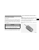
THINGS TO KNOW BEFORE STARTING YOUR VEHICLE A WORD ABOUT YOUR KEYS You can insert the double-sided keys into the locks with either side up. The dealer that sold you your new vehicle has the key code numbers for your vehicle locks. These numbers can be used to order duplicate keys only from an authorized dealer. Ask your dealer for these numbers and keep them in a safe place. CAUTION! An unlocked car is an invitation to thieves.
THINGS TO KNOW BEFORE STARTING YOUR VEHICLE Obtaining Replacement Keys Your vehicle is equipped with a theft deterrent locking system requiring a special key manufacturing process. For security reasons, replacement keys can only be obtained from your authorized dealer. Important! Removing the key from the steering lock activates the start lock-out. The engine cannot be started. Turning the key in the steering lock to the ON/RUN position deactivates the start lock-out.
THINGS TO KNOW BEFORE STARTING YOUR VEHICLE GLOVE COMPARTMENT LOCK The glove compartment can be locked by turning the key straight up to the vertical or right position, and then removing the key. To unlock the glove compartment, turn the key to the horizontal or left position, and then remove the key.
THINGS TO KNOW BEFORE STARTING YOUR VEHICLE The doors can be unlocked by pulling on the inside door handle, pressing and releasing the top portion of the central locking switch located in the console, or by pressing and releasing the Unlock transmit button on the key fob. Both doors can also be unlocked by turning the key counterclockwise in the driver’s door. NOTE: In case of a malfunction in the central locking system, the doors can be locked and unlocked individually.
THINGS TO KNOW BEFORE STARTING YOUR VEHICLE 13 NOTE: The fuel filler door and center console (roadster only) cannot be locked or unlocked with the central locking switch. NOTE: If you attempt to lock the doors with the key in the ignition and the driver’s door open, the doors will not lock. Automatic Central Locking The central locking switch also operates the automatic central locking feature.
THINGS TO KNOW BEFORE STARTING YOUR VEHICLE Perform the quick system check which follows: Use the remote transmitter to set the alarm. If the parking lamps flash three times, the system is operating properly. If not, there is a problem with a switch or the system. See your authorized dealer for service.
THINGS TO KNOW BEFORE STARTING YOUR VEHICLE 15 If the vehicle cannot be locked or unlocked by pressing the transmit button, then it may be necessary to change the batteries in the remote control. To Lock The Doors: Press the Lock button on the key fob once. All turn signal lights blink three times to indicate that the vehicle is locked. If the turn signal lights do not blink, a door or rear liftgate/decklid is not closed properly.
THINGS TO KNOW BEFORE STARTING YOUR VEHICLE To Use the Panic Alarm: Press and hold the Panic button to activate the alarm. Press and hold the Panic button or unlock the door with the key to deactivate the alarm. The alarm will also shut off after three minutes or when vehicle speed reaches 15 mph (24 km/h). 2. This device must accept any interference that may be received, including interference that may cause undesired operation.
THINGS TO KNOW BEFORE STARTING YOUR VEHICLE • Remove the old batteries. 17 approximately 30 seconds, insert the key in the ignition and turn it to the ON/RUN position. The remote control should once again be operational. SECURITY ALARM SYSTEM The system monitors the doors, rear liftgate/decklid, hood, and ignition for unauthorized operation. The security alarm system is automatically armed or disarmed with the remote control or any of your vehicle’s keys by locking or unlocking the vehicle.
THINGS TO KNOW BEFORE STARTING YOUR VEHICLE Tow-Away Alarm The tow-away alarm switch is located on the console. To deactivate for towing or jacking up the vehicle, press and release the upper portion of the switch. Press and release the upper portion to activate it again. After the alarm system has been armed, the exterior vehicle lights will flash and an alarm will sound when someone attempts to raise the vehicle.
THINGS TO KNOW BEFORE STARTING YOUR VEHICLE DECKLID INTERNAL EMERGENCY RELEASE ROADSTER WARNING! Do not allow children to have access to the trunk by climbing into the trunk from outside. Always close the decklid when your vehicle is unattended. Once in the trunk, young children may not be able to escape. If trapped in the trunk, children can die from suffocation or heat stroke.
THINGS TO KNOW BEFORE STARTING YOUR VEHICLE POWER WINDOWS The power window switches are located in the console. To operate, turn the key in the ignition switch to the ACC or ON/RUN position. Press the switch in to the resistance point to open; release the switch when the window is in the desired position. For express opening of windows, press the switch past the resistance point and release; the window lowers to the fully open position.
THINGS TO KNOW BEFORE STARTING YOUR VEHICLE Power Window Operation With The Convertible Top Switch (Roadster Only) The power windows can also be operated by using the convertible top switch. To operate, turn the key in the ignition switch to the ON/RUN position. Press down on the rear of the convertible top switch twice to open the windows. Press down on the front of the convertible top switch twice to close the windows.
THINGS TO KNOW BEFORE STARTING YOUR VEHICLE Please pay close attention to the information in this section. It tells you how to use your restraint system properly to keep you and your passengers as safe as possible. WARNING! In a collision, you and your passengers can suffer much greater injuries if you are not properly buckled up. You can strike the interior of your vehicle or other occupants, or you can be thrown out of the vehicle.
THINGS TO KNOW BEFORE STARTING YOUR VEHICLE The belt webbing retractor will lock only during very sudden stops or impacts. This feature allows the shoulder part of the belt to move freely with you under normal conditions. But, in a collision, the belt will lock and reduce the risk of your striking the inside of the vehicle or being thrown out. The seat belts are also equipped with emergency tensioning retractors.
THINGS TO KNOW BEFORE STARTING YOUR VEHICLE Lap/Shoulder Belt Operating Instructions 1. Enter the vehicle and close the door. Sit back and adjust the seat. 2. The seat belt latch plate is above the back of your seat. Grasp the latch plate and pull out the belt. Slide the latch plate up the webbing as far as necessary to make the belt go around your lap. 3. When the belt is long enough to fit, insert the latch plate into the buckle until you hear a “click.
THINGS TO KNOW BEFORE STARTING YOUR VEHICLE 4. Position the lap belt across your thighs, below your abdomen. To remove slack in the lap belt portion, pull up a little on the shoulder belt, as shown. 25 5. To loosen the lap belt if it is too tight, tilt the latch plate away from you and pull on the lap belt. Remember that a snug belt reduces the risk of sliding under the belt in a collision. 6. Position the shoulder belt on your chest so that it is comfortable and not resting on your neck.
THINGS TO KNOW BEFORE STARTING YOUR VEHICLE WARNING! WARNING! • A belt that is buckled into the wrong buckle will not protect you properly. The lap portion could ride too high on your body, possibly causing internal injuries. Always buckle your belt into the buckle nearest you. • A belt that is too loose will not protect you as well. In a sudden stop you could move too far forward, increasing the possibility of injury. Wear your seat belt snugly.
THINGS TO KNOW BEFORE STARTING YOUR VEHICLE WARNING! A frayed or torn belt could rip apart in a collision and leave you with no protection. Inspect the belt system periodically, checking for cuts, frays, or loose parts. Damaged parts must be replaced immediately. Do not disassemble or modify the system. Seat belt assemblies must be replaced after an accident if they have been damaged (bent retractor, torn webbing, etc.
THINGS TO KNOW BEFORE STARTING YOUR VEHICLE Supplemental Restraint System (SRS) - Airbag The vehicle is also equipped with side airbags, located in the driver and passenger doors. Side airbags also work with seat belts to improve occupant protection. WARNING! This vehicle has airbags for the driver and passenger as a supplement to the seat belt restraint systems. The driver’s airbag is mounted in the steering wheel.
THINGS TO KNOW BEFORE STARTING YOUR VEHICLE The seat belts are designed to protect you in many types of collisions. The front airbags deploy only in moderate to severe front collisions. In certain types of collisions, both the front and side airbags may be triggered. But even in collisions where the airbags work, you need the seat belts to keep you in the right position for the airbags to protect you properly. Here are some simple steps you can take to minimize the risk of harm from a deploying airbag. 1.
THINGS TO KNOW BEFORE STARTING YOUR VEHICLE WARNING! • Relying on the airbags alone could lead to more severe injuries in a collision. The airbags work with your seat belt to restrain you properly. In some collisions the airbags won’t deploy at all. Always wear your seat belts even though you have airbags. • Being too close to the steering wheel or instrument panel during airbag deployment could cause serious injury. • Airbags need room to inflate.
THINGS TO KNOW BEFORE STARTING YOUR VEHICLE How the Front Airbag System Works • A crash sensor in the occupant compartment determines if a frontal impact is severe enough to require the airbag. The sensor will not detect side, roll over, or rear impacts. The sensor is connected to the diagnostic unit and to the airbag/inflator unit. • The Occupant Restraint Controller monitors the readiness of the electronic parts of the system whenever the ignition switch is in the START or ON/RUN positions.
THINGS TO KNOW BEFORE STARTING YOUR VEHICLE • When the crash sensor detects an impact requiring the airbags, it signals the inflator units. A large quantity of nontoxic nitrogen gas is generated to inflate the airbags. The airbag covers separate and fold out of the way as the airbags inflate to their full size. The airbags then quickly deflate while helping to restrain the driver and passenger. The airbag gas is vented through the airbag material towards the instrument panel.
THINGS TO KNOW BEFORE STARTING YOUR VEHICLE The airbag system is designed to deploy when the impact sensors detect a moderate-to-severe frontal collision, to help restrain the driver and passenger, and then to immediately deflate. NOTE: A frontal collision that is not severe enough to need airbag protection will not activate the system. This does not mean something is wrong with the airbag system.
THINGS TO KNOW BEFORE STARTING YOUR VEHICLE • When a side impact above a predetermined threshold occurs, the sensors signal the inflator on the impacted side of the vehicle. A large quantity of nontoxic nitrogen gas is generated to inflate the airbag. The door panel opens to allow the airbag to inflate to its full size. WARNING! • Do not put anything on or around the airbag covers or attempt to manually open them.
THINGS TO KNOW BEFORE STARTING YOUR VEHICLE • The operational readiness of the side airbag system is verified by the airbag indicator light in the instrument cluster when turning the key in the ignition switch to the ON/RUN position. If no fault is detected, the light will go out after approximately four seconds. After the light goes out, the system continues to monitor the components and circuitry of the airbag system and will indicate a malfunction by coming on again.
THINGS TO KNOW BEFORE STARTING YOUR VEHICLE Passenger Front Airbag On/Off Switch The on/off switch is located at the right end of the instrument panel and is accessible by opening the passenger door.
THINGS TO KNOW BEFORE STARTING YOUR VEHICLE NOTE: When the passenger airbag is turned off, the yellow airbag off light will illuminate. • The air bag will remain off until the switch is turned back to the ON position. • The switch does NOT turn off the side airbag. To Shut Off the Passenger Airbag: • Place the ignition key in the on/off switch, turn the key clockwise, and remove the key from the switch. This will shut off the passenger front airbag.
THINGS TO KNOW BEFORE STARTING YOUR VEHICLE To Turn On the Passenger Airbag: • Place the ignition key in the on/off switch, turn the key counterclockwise, and remove the key from the switch. This will turn on the passenger airbag. The Passenger Airbag Off light on the console will turn off, or will not be illuminated when the ignition is turned to the ON position. WARNING! The airbag may malfunction and serious injury could result if key is left in the airbag shut off switch. Always remove the key.
THINGS TO KNOW BEFORE STARTING YOUR VEHICLE Airbag Light You will want to have the airbags ready for your protection in case of a collision. While the airbag Supplemental Restraint System (SRS) is designed to be maintenance free, if any of the following occurs, have an authorized dealer service the system immediately. • The AIRBAG light does not come on or flickers during the four seconds when the ignition switch is first turned on. • The light remains on or flickers after the four second interval.
THINGS TO KNOW BEFORE STARTING YOUR VEHICLE • Safety experts recommend that children ride rearward-facing in the vehicle until they are at least one year old and weigh at least 9 kg (20 lbs.). Two types of child restraints can be used rearward-facing: infant carriers and “convertible” child seats. • The infant carrier is only used rearward-facing in the vehicle. It is recommended for children who weigh up to about 20 lbs. (9 kg).
THINGS TO KNOW BEFORE STARTING YOUR VEHICLE • The restraint must be appropriate for your child’s weight and height. Check the label on the restraint for weight and height limits. • Carefully follow the instructions that come with the restraint. If you install the restraint improperly, it may not work when you need it. • Buckle the child into the seat according to the seat manufacturer’s directions.
THINGS TO KNOW BEFORE STARTING YOUR VEHICLE • Check belt fit periodically. A child’s squirming or slouching can move the belt out of position. • If the shoulder belt contacts the face or neck, move the child closer to the center of the vehicle. Never allow a child to put the shoulder belt under an arm or behind their back. LATCH - Child Seat Anchorage System (Lower Anchors and Tether for Children) Your vehicle’s passenger seat is equipped with the child restraint anchorage system called LATCH.
THINGS TO KNOW BEFORE STARTING YOUR VEHICLE The passenger seat tether anchorage is located on the back of the seat cushion frame. It is visible by moving the passenger seat forward in the vehicle. Many, but not all LATCH-Compatible child restraint systems will be equipped with separate straps on each side, with each having a hook or connector for attachment to the lower anchorage and a means of adjusting the tension in the strap.
THINGS TO KNOW BEFORE STARTING YOUR VEHICLE WARNING! Improper installation of a child restraint to the LATCH anchorages can lead to failure of an infant or child restraint. The child could be badly injured or killed. Follow the manufacturer’s directions exactly when installing an infant or child restraint. Installing Child Restraints Using the Vehicle Seat Belt Child restraints can be securely fastened in the passenger seat using the seat belts.
THINGS TO KNOW BEFORE STARTING YOUR VEHICLE To attach the tether strap to the anchor, move the seatback fully forward. Pass the child restraint tether hook over the top of the seat, through the strap near the top of the seat back, and attach it to the anchor bar behind the passenger seat, below the seatback. After securing the tether hook to the bar, recline the seatback fully rearward and move the seat to its most rearward position.
THINGS TO KNOW BEFORE STARTING YOUR VEHICLE ENGINE BREAK-IN RECOMMENDATIONS The engine in your new Crossfire does not require a long break-in period. Following these few simple guidelines is all that is necessary for a good break-in. • Drive your vehicle at moderate vehicle and engine speeds during the first 1,000 miles (1,600 km). • Do not make any full throttle starts and avoid full throttle acceleration. • Use the proper transmission gear for your speed range. • Avoid excessive idling.
THINGS TO KNOW BEFORE STARTING YOUR VEHICLE Safety Checks You Should Make Inside the Vehicle Seat Belts Inspect the belt system periodically, checking for cuts, frays and loose parts. Damaged parts must be replaced immediately. Do not disassemble or modify the system. Seat belt assemblies must be replaced after an accident if they have been damaged (bent retractor, torn webbing, etc.). If there is any question regarding belt or retractor condition, see your authorized dealer.
UNDERSTANDING THE FEATURES OF YOUR VEHICLE CONTENTS 3 䡵 Convertible Top Operation . . . . . . . . . . . . . . . .52 䡵 Mirrors . . . . . . . . . . . . . . . . . . . . . . . . . . . . . .66 ▫ To Lower The Top . . . . . . . . . . . . . . . . . . . . . .53 ▫ Inside Day/Night Mirror . . . . . . . . . . . . . . . . .66 ▫ To Raise The Top . . . . . . . . . . . . . . . . . . . . . .57 ▫ Exterior Mirrors Folding Feature . . . . . . . . . . .66 ▫ Convertible Top Lamp And Audible Signal Chart . . . . . . . . .
UNDERSTANDING THE FEATURES OF YOUR VEHICLE 䡵 To Open And Close The Hood . . . . . . . . . . . . .70 ▫ Mist Function . . . . . . . . . . . . . . . . . . . . . . . . .78 䡵 Interior Lights . . . . . . . . . . . . . . . . . . . . . . . . .71 䡵 Telescoping Steering Column . . . . . . . . . . . . . .79 ▫ Front Map/Reading Lights . . . . . . . . . . . . . . .72 䡵 Tire Pressure Monitor System . . . . . . . . . . . . . .80 ▫ Battery Saver Feature . . . . . . . . . . . . . . . . . . .72 䡵 Rear Spoiler . .
UNDERSTANDING THE FEATURES OF YOUR VEHICLE 51 ▫ Erasing Universal Transceiver Buttons . . . . . . . .95 ▫ Security . . . . . . . . . . . . . . . . . . . . . . . . . . . . .96 ▫ Reprogramming a Single Button . . . . . . . . . . . .96 䡵 Umbrella Hook . . . . . . . . . . . . . . . . . . . . . . . .
UNDERSTANDING THE FEATURES OF YOUR VEHICLE CONVERTIBLE TOP OPERATION WARNING! The convertible top does not provide the structural protection that a reinforced metal roof does and the fabric top cannot be expected to prevent the ejection of the occupants of a vehicle in a collision. Therefore, it is important that all occupants wear their seat belts at all times when riding in a convertible.
UNDERSTANDING THE FEATURES OF YOUR VEHICLE CAUTION! When opening and closing the convertible top, make sure that: • There is sufficient clearance of at least 6 ft. (1.8m) for the convertible top to move up. • Nothing is placed on the tonneau cover. • The outside temperature is above 32°F (0°C). Otherwise the convertible top and other parts of the vehicle could be damaged. 53 To Lower The Top: WARNING! Top operation can be suspended for a maximum of 10 minutes.
UNDERSTANDING THE FEATURES OF YOUR VEHICLE CAUTION! CAUTION! To avoid possible damage to the tonneau cover and convertible top, do not allow the convertible top to remain in the suspended position. After approximately 10 minutes in the suspended position, the hydraulic pressure will be released which will allow the top and the tonneau cover to lower. The convertible top switch can be pressed to cancel this operation.
UNDERSTANDING THE FEATURES OF YOUR VEHICLE 55 2. Make sure the decklid is closed. CAUTION! Be sure to turn the ignition to the “ON/RUN” position before releasing the top from the windshield header. The windows will not go down if the top is released from the header without the ignition turned “ON”. The side windows can be damaged if the doors are opened or closed with the windows up and the top released from the winshield header. 3. Turn the ignition key to the ON/RUN position. 4.
UNDERSTANDING THE FEATURES OF YOUR VEHICLE NOTE: Once the release handle is rotated, the windows will automatically go down. 5. Push up on the convertible top latch handle to create a gap between the header and top of approximately 8 inches (200 mm). As soon as the top is free, rotate the latch handle counterclockwise just over one quarter turn and push it up into the stored position.
UNDERSTANDING THE FEATURES OF YOUR VEHICLE NOTE: Once the top is lowered and the audible signal is heard, you can continue to push the convertible top switch down or push it within 2 seconds to raise the windows. The windows can also be closed/opened later using the power window switches. 57 CAUTION! To prevent mildew, the convertible top must be dry before lowering it into the storage compartment. Do not lower a frozen convertible top until thawed and dry.
UNDERSTANDING THE FEATURES OF YOUR VEHICLE 3. Turn the ignition key to the ON/RUN position and press down on the front of the convertible top switch. NOTE: If the top is latched to the windshield header before the rear of the top is properly latched, an udible warning will sound. 5. Push the latch handle release button, pull the latch handle down from the storage position and turn it clockwise just over one quarter turn. 6.
UNDERSTANDING THE FEATURES OF YOUR VEHICLE 7. When the top engages to the header, turn the latch handle counterclockwise just over one quarter turn to the lock position and push the latch handle up to the stored position. The top is now secured in the closed position. NOTE: The convertible top switch indicator will light up and an audible warning will be heard if you start driving the vehicle without the top fully locked in the closed position.
UNDERSTANDING THE FEATURES OF YOUR VEHICLE Convertible Top Lamp and Audible Signal Chart Below is a table containing all of the visual and audible signals that can be seen or heard during the tops operation or if a fault is present.
UNDERSTANDING THE FEATURES OF YOUR VEHICLE Convertible top switch lamp flashes quickly and a quick audible beep is heard Convertible top switch lamp flashes rapidly Maximum hydraulic pump run-time reached Power window motor(s) or rear spoiler inoperative Vehicle speed greater than 9 mph (15 km/h) during top operation Top operation suspended longer than 10 minutes General top control module fault CONSOLE FEATURES The console has a power outlet/cigar lighter, an ash tray with a coin holder, a cupholder, a
UNDERSTANDING THE FEATURES OF YOUR VEHICLE Storage Compartments There is a storage compartment in the console. To open the storage compartment, lift the lid with the finger depressions on either side. To close, lower the lid until the lock engages. Additionally, storage pockets are located on the wall behind each seat and on each door panel. A storage pouch is located on the rear wall between the seats, and the driver’s sunvisor has a document strap.
UNDERSTANDING THE FEATURES OF YOUR VEHICLE 63 WARNING! WARNING! Keep compartment lids closed. This will help to prevent stored objects from being thrown about and injuring vehicle occupants during an accident. Remove the ashtray only with the vehicle stopped and the ignition off. Otherwise, the vehicle might move unexpectedly as a result of unintended contact with the gear selector lever. Ashtray Lightly touch the bottom of the ashtray cover. The ashtray will open automatically.
UNDERSTANDING THE FEATURES OF YOUR VEHICLE Coin Holder With the ashtray open, folding down the cover plate reveals the coin holder, which can accommodate nine coins in various sizes up to a U.S. quarter. The coin slots are shaped to retain the coins, and the cover plate ensures that the coins remain in the coin holder. Power Outlet/Cigar Lighter The dual-purpose power outlet is located in the console, next to the passenger airbag off warning light.
UNDERSTANDING THE FEATURES OF YOUR VEHICLE 65 Glove Compartment To lock the glove compartment, turn the key to the right and remove. To unlock, turn the key to the left and remove. Pull on the handle to open the glove compartment. 3 CUPHOLDER The cupholder is located in the console. To open the cupholder, gently press downward on the front edge of the top panel, and then release. The cupholder will open automatically.
UNDERSTANDING THE FEATURES OF YOUR VEHICLE MIRRORS Inside Day/Night Mirror Adjust the mirror to center on the view through the rear window. A two point pivot system allows for horizontal and vertical mirror adjustment. Exterior Mirrors Folding Feature All exterior mirrors are hinged to move forward or rearward to resist damage. The hinges have three detent positions: full forward, full rearward, and normal.
UNDERSTANDING THE FEATURES OF YOUR VEHICLE Power Remote Control Outside Mirrors The mirrors can be adjusted by using the remote control located in the console. Rotate the switch to the right to select the right mirror, rotate to the left to select the left mirror. Then use the switch to adjust the selected mirror to the desired direction.
UNDERSTANDING THE FEATURES OF YOUR VEHICLE Vanity Mirrors SEATS Driver Eight-Way Power Seat The switches to adjust the power seats are located on the outboard side of each seat. The driver’s seat features eight-way power adjustment - horizontal, vertical, cushion tilt and back angle. A vanity mirror is on each sun visor. To use the mirror, rotate the sun visor down and slide open the mirror cover.
UNDERSTANDING THE FEATURES OF YOUR VEHICLE 69 Passenger Four-Way Power Seat The switches to adjust the passenger seat are also on the outboard side of the seat. The passenger seat provides four-way adjustment - horizontal and back angle.
UNDERSTANDING THE FEATURES OF YOUR VEHICLE Heated Seats This feature heats the driver and passenger seats. The controls for the heated seats are located on the instrument panel, below the radio. After turning the ignition switch ON, you can choose the HI, LO, or OFF setting. Indicators on the switches show which setting has been selected. The heated seats setting will automatically switch from HI to LO after approximately 5 minutes.
UNDERSTANDING THE FEATURES OF YOUR VEHICLE To prevent possible damage, close the hood by dropping it from approximately 12 inches (30 cm). 71 INTERIOR LIGHTS A two-position mode selector switch controls the interior lights located in the overhead console. 3 WARNING! If the hood is not fully latched, it could fly up when the vehicle is moving, and block your forward vision. You could have a collision. Be sure all hood latches are fully latched before driving.
UNDERSTANDING THE FEATURES OF YOUR VEHICLE Front Map/Reading Lights These lights are located between the sun visors. A single centrally located switch operates both lights. Battery Saver Feature To prevent battery drain if a door is left open or ajar, the interior lights will turn off automatically after 15 minutes. After the door is closed, the interior lights will return to their normal function.
UNDERSTANDING THE FEATURES OF YOUR VEHICLE EXTERIOR LIGHTS Headlights and Parking Lights When the headlight switch is turned clockwise from OFF to the first position, the parking lights, taillights, side marker lights, license plate lights and instrument panel lights are all illuminated. 73 Lights-On Reminder If the headlights or parking lights are left on after the ignition is turned off, a warning will sound if the driver’s door is opened.
UNDERSTANDING THE FEATURES OF YOUR VEHICLE Fog Lights To operate the fog lights, pull the headlight switch out one stop, with the parking lights and/or low beam headlights on. A light to the lower left of the headlight switch will illuminate when the fog lights are on. To turn off the fog lights, push the headlight switch in fully. Selecting high beam headlights will also turn off the fog lights.
UNDERSTANDING THE FEATURES OF YOUR VEHICLE MULTIFUNCTION CONTROL LEVER 75 To operate the turn signals continuously, move the control lever up or down past the point of resistance. The operation is automatically canceled when the steering wheel is turned to a large enough degree. If one of the turn signal lights fail, the turn signal indicator system flashes and sounds at a faster than normal rate.
UNDERSTANDING THE FEATURES OF YOUR VEHICLE Headlight Dimmer Switch Push the multifunction control lever toward the instrument panel to turn the headlights to high beam. Pull the lever toward you to switch to low beam. Passing Light You can signal another vehicle with your headlights by lightly pulling the multifunction control lever toward the steering wheel. This will cause the headlights to turn on at high beam and remain on until the control lever is released.
UNDERSTANDING THE FEATURES OF YOUR VEHICLE Windshield Wipers And Washer The wipers and washer are operated by a switch in the multifunction control lever. Turn the end of the lever to select desired wiper speed: off, intermittent, normal, or fast. 77 Push the end of the lever inward and hold it to activate the wiper and washer together.
UNDERSTANDING THE FEATURES OF YOUR VEHICLE Mist Function Push the end of the multifunction control lever inward briefly for a single wipe without adding washer fluid. Use this feature only when the windshield is wet. WARNING! Sudden loss of visibility through the windshield could lead to an accident. You might not see other vehicles or other obstacles. To avoid sudden icing of the windshield during freezing weather, warm the windshield with the defroster before and during windshield washer use.
UNDERSTANDING THE FEATURES OF YOUR VEHICLE TELESCOPING STEERING COLUMN Unlock the steering column by pulling out the handle located directly below the column. The indicator light located in the instrument cluster will come on. To lengthen or shorten the steering column, pull out or push in the steering wheel. Lock the steering column in position by pushing the handle in until it engages. The indicator light in the instrument cluster will go out. 79 WARNING! Do not adjust the steering wheel while driving.
UNDERSTANDING THE FEATURES OF YOUR VEHICLE NOTE: If the indicator light in the instrument cluster does not go out after starting the engine, the telescoping column is not locked properly. Do not drive the vehicle until you have properly locked the steering column. TIRE PRESSURE MONITOR SYSTEM The Tire Pressure Monitor (TPM) system uses wireless technology to monitor tire pressure levels.
UNDERSTANDING THE FEATURES OF YOUR VEHICLE 81 CAUTION! The TPM system is designed to monitor your tire pressure and will not function as a tire pressure gauge. After adjusting the air pressure in a tire, there will be a delay before the system updates the display. The TPM system will cause the indicator lamp in the instrument cluster to illuminate whenever the pressure in one tire falls 25% below the recommended pressure shown on the vehicle’s tire label.
UNDERSTANDING THE FEATURES OF YOUR VEHICLE NOTE: The standard TIREFIT system (refer to What To Do In Emergencies for more information) is specifically designed to operate in conjunction with the TPM system, and will not damage the sensors. If your tire pressure is low, you should correct your tire inflation pressure as soon as possible and inspect all of your tires. Low tire pressure will cause the tire pressure light to illuminate and the alert will sound.
UNDERSTANDING THE FEATURES OF YOUR VEHICLE 83 The spoiler control also incorporates an emergency stop feature. If, for any reason, spoiler motion needs to be stopped, pressing either the top or bottom of the switch will stop the spoiler motion. Once the deployment speed is reached, however, the spoiler deploys to its full up position. The spoiler can also be deployed at lower speeds using an override switch mounted in the center console.
UNDERSTANDING THE FEATURES OF YOUR VEHICLE Should a malfunction occur that prevents the spoiler from deploying automatically, a red warning light will illuminate in the override switch and an audible warning will sound. WARNING! Do not drive the vehicle at speeds above 62 mph (100 km/h) if the red spoiler warning indicator is illuminated. You could have reduced vehicle stability and control.
UNDERSTANDING THE FEATURES OF YOUR VEHICLE BRAKE ASSIST SYSTEM (BAS) WARNING! BAS cannot prevent the natural laws of physics from acting on the vehicle, nor can it increase braking efficiency beyond that afforded by the condition of the vehicle brakes and tires or the traction afforded. The BAS cannot prevent accidents, including those resulting from excessive speed in turns, following another vehicle too closely, or hydroplaning. Only a safe, attentive, and skillful driver can prevent accidents.
UNDERSTANDING THE FEATURES OF YOUR VEHICLE turned to the ON/RUN position. They should go out with the engine running. If the BAS/ESP malfunction indicator light comes on continuously with the engine running, a malfunction has been detected in either system. If the malfunction indicator light stays illuminated, have the BAS and ESP checked at your authorized dealer as soon as possible.
UNDERSTANDING THE FEATURES OF YOUR VEHICLE To improve the vehicle’s traction when driving with snow chains, or starting off in deep snow, sand or gravel, switch off the ESP system by pressing the upper half of the ESP switch. 87 wheel regains sufficient traction. The traction control engages at approximately 24 mph (40 km/h), and switches off at 50 mph (80 km/h). If the ESP warning light begins to flash during acceleration, ease up on the accelerator and apply as little throttle as possible.
UNDERSTANDING THE FEATURES OF YOUR VEHICLE Synchronizing ESP If the power supply was interrupted (battery disconnected or discharged), the BAS/ESP malfunction indicator light may be illuminated with the engine running. To re-synchronize the ESP, and cancel the malfunction indicator light, the steering angle sensor will need to be recalibrated. 1. Turn the ignition switch to the ON/RUN position. 2. Rotate the steering wheel to the center position. 3.
UNDERSTANDING THE FEATURES OF YOUR VEHICLE 89 3 To accelerate and set a speed, lift the lever up. Lift and hold the lever to accelerate, or lift and release to set a speed. To decelerate and set a speed, press the lever down. Press down and hold the lever to decelerate, or press down and release to set a speed. WARNING! Leaving the electronic speed control system on when not in use is dangerous. You could accidentally set the system or cause it to go faster than you want.
UNDERSTANDING THE FEATURES OF YOUR VEHICLE To Vary The Speed Setting If a set speed needs to be adjusted slightly, lift up or hold down the speed control lever briefly until the desired speed is reached. A single tap on the lever up or down will change the speed in 0.6 mph (1 km/h) increments. When the lever is released, the newly set speed remains. To increase the speed for passing, use the accelerator. After the accelerator is released, the previously set speed will resume automatically.
UNDERSTANDING THE FEATURES OF YOUR VEHICLE To Resume Speed To resume a previously set speed, pull the speed control lever toward you, and then release. The resume feature can be used at any speed above 20 mph (30 km/h). 91 Using Speed Control On Hills Your vehicle is equipped with interactive speed control. This feature activates when driving up or down hills with the speed control engaged and the driver’s foot off the accelerator.
UNDERSTANDING THE FEATURES OF YOUR VEHICLE For vehicles with manual transmission: The set speed control is switched off when declutching exceeds four seconds during downshifting. In some cases, you may have to step on the brake pedal to slow down sufficiently to achieve the desired speed. NOTE: On very steep hills, a greater speed loss or gain may occur. It may be preferable to drive without speed control.
UNDERSTANDING THE FEATURES OF YOUR VEHICLE 93 WARNING! NOTE: Step 3 does not have to be followed to program additional hand-held transmitters. Vehicle exhaust contains carbon monoxide, a dangerous gas. Do not run the vehicle’s engine while programming the transceiver. Exhaust gas can cause serious injury or death. 4. Choose one of the three buttons to program. Place the hand-held controller 1–3 inches (25–76 mm) from the universal transceiver while keeping its indicator light in view.
UNDERSTANDING THE FEATURES OF YOUR VEHICLE NOTE: Some gate operators and garage door openers may require you to replace this Programming Step 5 with procedures noted in the “Gate Operator/Canadian Programming” section. 6. The indicator light in the universal transceiver will begin to flash, first slowly and then rapidly. Release both buttons after the indicator light changes from slow to rapid flash.
UNDERSTANDING THE FEATURES OF YOUR VEHICLE If you do not successfully program the universal transceiver to learn the signal of your hand-held transmitter, call toll free for customer assistance at 1-800-355-3515, or on the internet at www.homelink.com. Gate Operator/Canadian Programming Canadian radio-frequency laws require transmitter signals to “time-out” (or quit) after several seconds of transmission. This may not be long enough for the universal transceiver to pick up the signal during programming.
UNDERSTANDING THE FEATURES OF YOUR VEHICLE Reprogramming a Single Button To program a device using a universal transceiver button previously programmed, follow these steps: 2. This device must accept any interference that may be received, including interference that may cause undesired operation. 1. Press and hold the desired universal transceiver button. DO NOT release the button.
UNDERSTANDING YOUR INSTRUMENT PANEL CONTENTS 䡵 Instruments And Controls . . . . . . . . . . . . . . . . .98 ▫ Driver – L/R . . . . . . . . . . . . . . . . . . . . . . . . 119 䡵 Instrument Cluster . . . . . . . . . . . . . . . . . . . . . .99 ▫ Telephone Mute Characteristics . . . . . . . . . . . 119 䡵 Instrument Cluster Description . . . . . . . . . . . . .99 䡵 Compact Disc Maintenance . . . . . . . . . . . . . . .
UNDERSTANDING YOUR INSTRUMENT PANEL INSTRUMENTS AND CONTROLS
UNDERSTANDING YOUR INSTRUMENT PANEL INSTRUMENT CLUSTER The instrument cluster displays are activated by either opening the door, pressing the left button within the cluster, or turning the key in the ignition switch to the ON/RUN position. 99 INSTRUMENT CLUSTER DESCRIPTION 1. Low Windshield Washer System Fluid Level Warning Light With the key in the ignition switch turned to the ON/RUN position, the indicator light comes on. It should go out when the engine is running.
UNDERSTANDING YOUR INSTRUMENT PANEL WARNING! CAUTION! Do not overfill the washer reservoir. Do not attempt to fill to the top of the filler neck. Fluid may leak out onto the floor or driveway causing a potential slip and fall hazard. When the indicator light first illuminates, the maximum fill amount is 1 Gallon (4 Liters). The TPM system is designed to monitor your tire pressure and will not function as a tire pressure gauge.
UNDERSTANDING YOUR INSTRUMENT PANEL 3. Coolant Indicator Light This indicator illuminates when the engine coolant has dropped below the required level in the reservoir or the coolant temperature is too high (see the Temperature gauge section). To check the coolant level, the vehicle must be parked on level ground and the engine stopped. Check coolant level only when the coolant is cold. 101 4. Engine Coolant Temperature Gauge This gauge shows engine coolant temperature.
UNDERSTANDING YOUR INSTRUMENT PANEL 6. Turn Signal Indicators To signal minor directional changes, such as changing lanes, move the multifunction control lever to the point of resistance only and hold it there. The arrows will flash in unison with the corresponding exterior turn signal. To operate the turn signals continuously, move the multifunction control lever past the point of resistance up or down. The switch is automatically canceled when the steering wheel is turned to a large enough degree.
UNDERSTANDING YOUR INSTRUMENT PANEL The warning light should be checked frequently to assure that it is operating properly. This can be done by turning the ignition switch to START. The light should come on. If the red brake light does not come on when the ignition is turned to the ON/RUN position, have the brake light repaired promptly. WARNING! Driving a vehicle with the brake light on is dangerous. Part of the brake system may have failed. It will take longer to stop the vehicle.
UNDERSTANDING YOUR INSTRUMENT PANEL If the ABS warning indicator light comes on while the engine is running, it indicates that the ABS has detected a malfunction and has switched off. In this case, the brake system functions in the usual manner, but without antilock assistance. If the ABS light is on, have the system checked at your authorized dealer as soon as possible. 13.
UNDERSTANDING YOUR INSTRUMENT PANEL If the charging system indicator light comes on, or a loss of power steering assistance is noticeable while the engine is running, this may indicate that the accessory drive belt has broken. Should this condition occur, the belt must be replaced before continuing to operate the vehicle. 105 17. Electronic Digital Clock A digital readout in the instrument cluster shows the time in hours and minutes whenever the ignition switch is in the ON/RUN or ACC position.
UNDERSTANDING YOUR INSTRUMENT PANEL 20. Trip Odometer, Flexible Service System (FSS) Indicator This display shows the distance traveled since last reset. To reset: • Press the button to the left of the display once (with the key in the ON/RUN position). • Press the button twice (with the key removed or in the OFF/LOCK or ACC position). 21. Main Odometer, Flexible Service System (FSS) This shows the total distance the vehicle has been driven. U.S.
UNDERSTANDING YOUR INSTRUMENT PANEL Depending on operating conditions throughout the year, the next service is calculated and displayed next to this symbol in days remaining before the next service is required. Likewise, the next service may be calculated and displayed next to this symbol as distance remaining before the next service is required. The counter can also be reset by any individual after the indicated service has been performed. To do so: 1. Turn key to the ON/RUN position. 2.
UNDERSTANDING YOUR INSTRUMENT PANEL Following a completed A or B service your authorized dealer sets the counter to 7,000 miles (Canada: 11,000 km). NOTE: When disconnecting vehicle battery for one or more days at a time, such days will not be counted. Any such days not counted by FSS can be added by your authorized dealer. The interval between services is determined by the type of vehicle operation.
UNDERSTANDING YOUR INSTRUMENT PANEL 24. Airbag Light The operational readiness of the airbag system is verified by the airbag indicator light in the instrument cluster when turning the key in the ignition switch to the ACC or ON/RUN position. If no fault is detected, the light will go out after approximately 4 seconds. After the lamp goes out, the system continues to monitor the components and circuitry of the airbag system and will indicate a malfunction by coming on again.
UNDERSTANDING YOUR INSTRUMENT PANEL WARNING! Do not drive the vehicle until you have properly locked the steering column. 26. Check Engine Light This light is part of an onboard diagnostic system that monitors the emissions and engine control systems. If a problem is detected in one of these systems, the Check Engine light will come on. The light comes on and stays on briefly as a bulb check when the ignition is first turned on.
UNDERSTANDING YOUR INSTRUMENT PANEL CHECKING ENGINE OIL LEVEL A sensor in the oil pan allows oil level to be checked without opening the hood. It provides an accurate measurement of oil level, whereas the low engine oil level indicator warns that oil level is definitely too low. With the vehicle parked on a level surface, the engine is warmed up and shut off for approximately five minutes.
UNDERSTANDING YOUR INSTRUMENT PANEL “INFINITY MODULUS” AM/FM STEREO RADIO WITH SINGLE-DISC CD PLAYER AND GPS NAVIGATION (OPTIONAL - See separate User’s Manual) “INFINITY MODULUS” AM/FM STEREO RADIO WITH SINGLE-DISC CD PLAYER INFINITY MODULUS Entertainment Systems A premium Infinity Modulus AM/FM stereo, single-disc CD audio system is standard equipment in your Crossfire.
UNDERSTANDING YOUR INSTRUMENT PANEL The volume is controlled by rotating the ON/OFF knob to the left or right. Audio (AUD) Settings • Bass (BASS) Press the AUD button repeatedly until BASS appears. Rotate the right rotary control for the desired level (from -9 to +9). • Treble (TREB) Press the AUD button repeatedly until TREB appears. Rotate the right rotary control for the desired level (from -9 to +9). • Balance (BAL) Press the AUD button repeatedly until BAL appears.
UNDERSTANDING YOUR INSTRUMENT PANEL FM AS – An autostore feature will store the 9 current stations with the strongest signal on station buttons 1-9 in the order of their signal quality. Press the FM button repeatedly until FM AS is displayed to perform an autostore scan. Press the multifunction button labeled AS repeatedly until AS-SEEK is displayed. To select the stored stations, press the 1-9 buttons.
UNDERSTANDING YOUR INSTRUMENT PANEL currently available PTY by turning the right rotary control/push button and the program type scan search begins. Press the button again to keep the received program. If the selected station does not transmit a PTY identification, the display will show NO PTY. If all criteria for evaluating RDS are not met, the unit will only display the frequency.
UNDERSTANDING YOUR INSTRUMENT PANEL AM-AM AS The system has two AM modes available. Press the AM button repeatedly until the band or operation mode is selected. To search in this mode, press the right rotary control/push button and the abbreviation SC is displayed. Receivable stations can be heard for eight seconds. Press the control again to keep the received station. Once the scan search begins, it will continue until either a station is retained or until another mode is selected.
UNDERSTANDING YOUR INSTRUMENT PANEL Insert the CD into the slot with the printed side up. The unit will display the number of tracks and total playback time. After the last track has been played back, the unit automatically begins to play the first track again. To eject a disc, briefly press and release the EJT button. If the power is turned off, the disc will remain in the CD slot for protection. Features of the CD player: • Skipping Tracks Turn the right rotary control/push button.
UNDERSTANDING YOUR INSTRUMENT PANEL NOTE: To protect the unit from excessive heat, a temperature protection device has been integrated into the circuitry. When a high operating temperature is detected, CD TEMP is displayed for eight seconds and the unit switches back to the last source (AM or FM). Allow sufficient cool down time and retry.
UNDERSTANDING YOUR INSTRUMENT PANEL • STEREO – Setting for exceptional conditions. The unit is constantly set for stereo reception (primarily for private broadcasters in urban areas). • MONO – Setting for receptions with constant reflection, the unit is constantly set for monaural reception. You can also call up the Setting DRIVER mode by pressing the right rotary/push button at this time. Driver – L/R If a telephone with hands-free operation is installed, the call is routed through the speaker system.
UNDERSTANDING YOUR INSTRUMENT PANEL COMPACT DISC MAINTENANCE To keep the compact discs in good condition, take the following precautions: 1. Handle the disc by its edge; avoid touching the surface. 2. If the disc is stained, clean the surface with a soft cloth, wiping from center to edge. 3. Do not apply paper or tape to the disc; avoid scratching the disc. 4. Do not use solvents such as benzine, thinner, cleaners, or antistatic sprays. 5. Store the disc in its case after playing. 6.
UNDERSTANDING YOUR INSTRUMENT PANEL CLIMATE CONTROLS 121 The climate control system allows you to balance the temperature, amount and direction of the air circulating throughout the vehicle. The system is always at operational readiness, except when manually switched off. The climate control only operates with the engine running.
UNDERSTANDING YOUR INSTRUMENT PANEL The temperature selector should be left at the desired temperature setting so that the system can automatically reach that selection as quickly as possible. The inside temperature will not heat or cool any quicker by setting the selector higher or lower upon initial start up. Select a temperature for each side of the passenger compartment. Select air volume with the fan control switch.
UNDERSTANDING YOUR INSTRUMENT PANEL 123 Slight changes in engine speed or power may be noticed when the compressor is on. This is a normal occurrence, since the compressor will cycle on and off to maintain comfort and increase fuel economy. NOTE: If your air conditioning performance seems lower than expected, check the front of the A/C condenser for an accumulation of dirt or insects. NOTE: The dot between the air distribution control icons is a mix position between the two modes.
UNDERSTANDING YOUR INSTRUMENT PANEL Defogging Windows Fogged Up On Inside Press the A/C button; the indicator light should illuminate. Switch off the air recirculation; the indicator light should go out. Set the air distribution control switch to the defrost position. Increase air volume with the fan control switch. Close the center, left, and right side air outlets. Turn the defroster outlets for the side windows to the detent position.
UNDERSTANDING YOUR INSTRUMENT PANEL Climate Control - OFF To switch the climate control off, set the air volume control switch to position 0. The fresh air supply to the vehicle interior is shut off. While driving, use this setting only temporarily, otherwise the windshield could fog up. 125 inside the switch starts blinking. As soon as the battery has sufficient voltage, the defroster automatically turns itself back on.
UNDERSTANDING YOUR INSTRUMENT PANEL after approximately 30 minutes, at outside temperatures above approximately 40°F (5°C); after approximately five minutes, if the A/C button is pressed. At high outside temperatures, the system automatically engages the recirculated air mode for approximately 30 minutes, thereby increasing the cooling capacity performance. Press the recirculation button again to extend the recirculated air mode.
UNDERSTANDING YOUR INSTRUMENT PANEL 127 Operating Tips 4
STARTING AND OPERATING CONTENTS 䡵 Starting Procedures . . . . . . . . . . . . . . . . . . . . 131 ▫ Park Position . . . . . . . . . . . . . . . . . . . . . . . . 137 ▫ Normal Starting . . . . . . . . . . . . . . . . . . . . . . 131 ▫ Reverse . . . . . . . . . . . . . . . . . . . . . . . . . . . . 138 ▫ Extremely Cold Weather (Below -20°F Or -29°C) . . . . . . . . . . . . . . . . . 132 ▫ Neutral . . . . . . . . . . . . . . . . . . . . . . . . . . . . 138 ▫ If Engine Fails To Start . . . . . . . . . . .
STARTING AND OPERATING ▫ Electronic Stability Program (ESP) . . . . . . . . . 146 ▫ Tread Wear Indicators . . . . . . . . . . . . . . . . . . 160 ▫ Synchronizing ESP . . . . . . . . . . . . . . . . . . . . 147 ▫ Replacement Tires . . . . . . . . . . . . . . . . . . . . . 160 ▫ ESP Control Switch . . . . . . . . . . . . . . . . . . . . 148 ▫ Tire Rotation Recommendations . . . . . . . . . . . 162 ▫ Anti-Lock Brake System (ABS) . . . . . . . . . . . . 149 ▫ Alignment And Balance . . . . . . . . .
STARTING AND OPERATING STARTING PROCEDURES WARNING! Do not leave animals or children inside parked vehicles in hot weather; interior heat build up may cause serious injury or death. Be sure that the parking brake is engaged and that selector lever is in the NEUTRAL or PARK position (gearshift lever in Neutral). Turn the key in the ignition switch to the ON/RUN position. Apply the brakes before shifting into any driving gear.
STARTING AND OPERATING NOTE: Due to the starter non-repeat feature, the key must be turned completely to the left before attempting to start the engine again. If Engine Fails to Start CAUTION! Do not try to push or tow your vehicle to get it started. Your vehicle cannot be started this way. Pushing with another vehicle may damage the transmission or the rear of your vehicle. See Section 6 of this manual for proper jump-starting procedures.
STARTING AND OPERATING If the engine fails to start after you have followed the Normal Starting procedure, it may be flooded. Push the accelerator pedal all the way to the floor and hold it there while cranking the engine. This should clear any excess fuel in case the engine is flooded. 133 After Starting The idle speed will automatically decrease as the engine warms up.
STARTING AND OPERATING Fully depress the clutch pedal before you shift gears. As you release the clutch pedal, lightly depress the accelerator pedal. NOTE: During cold weather, until the transmission lubricant has warmed, you may have difficulty shifting. This is normal and not harmful to the transmission. Be sure the transmission is in FIRST gear, (not THIRD), when starting from a stopped position. Damage to the clutch can result from starting in THIRD.
STARTING AND OPERATING WARNING! 135 Automatic Transmission When leaving the vehicle, always remove the key from the ignition switch, and lock the vehicle. Do not leave children unattended in the vehicle, or with access to an unlocked vehicle. Children could move the gearshift lever, which could result in an accident or serious injury. 5 WARNING! Skipping more than one gear while downshifting could cause you to lose control of your vehicle. You could have an accident.
STARTING AND OPERATING The gear shifting process is continuously adapted, dependent on the driving style, the driving situation and the road characteristics. The selector lever is automatically locked while in the PARK position. To move the selector lever out of the PARK position, the brake pedal must be firmly depressed before the shift lock will release. Shift the selector lever to the desired position only when the engine is idling normally and the brake pedal is applied.
STARTING AND OPERATING Maneuvering To maneuver in tight areas, control the vehicle speed by gradually releasing the brakes. Accelerate gently and never abruptly step on the accelerator. To rock a vehicle out of soft ground (mud or snow), alternately shift from forward to reverse, while applying only slight acceleration. Rocking a vehicle free in this manner may cause the ABS or traction system malfunction indicator light to come on.
STARTING AND OPERATING With a malfunction in the vehicle’s electrical system, the selector lever could remain locked in the PARK position. To unlock the selector lever manually, insert the end of the multipurpose tool from the glove box (or ball point pen) into the covered opening below the position “D” of the shift pattern. While pushing the tool down, move the selector lever out of the PARK position. After removal of the tool from the opening, the cover will not close fully.
STARTING AND OPERATING Drive The transmission automatically upshifts through fifth gear. The DRIVE position provides optimum driving characteristics under all normal operating conditions. AutoStick姞 Gear selection The transmission gear can be selected by pressing the selector lever to the right or the left with the selector lever in the DRIVE position. The gear currently selected is indicated in the instrument cluster display. Briefly press selector lever in the “D-” direction.
STARTING AND OPERATING The delayed upshift is effective with vehicle speeds below 31 mph (50 km/h) at partial throttle and engine temperatures below 95°F (35°C). To prevent the engine from laboring at low RPM when driving uphill or with your vehicle heavily loaded, the automatic transmission will downshift when necessary to maintain engine RPM within the best torque range. “R” REVERSE Shift into this range only after the vehicle has come to a complete stop.
STARTING AND OPERATING 141 For Winter/Wet (snow and ice) mode, press the “W” symbol on the switch. The vehicle starts out in SECOND gear, unless FIRST gear has been selected, or the accelerator pedal is in the kickdown position. The “W” mode helps to improve traction and driving stability of the vehicle. The gear shifting process occurs at lower vehicle and engine speeds than in the “S” program mode. CAUTION! For standard mode, press the “S” symbol on the switch. Use this mode for all regular driving.
STARTING AND OPERATING In this mode only the SECOND gear or REVERSE gear can be activated. To engage SECOND gear or REVERSE: 1. Stop the vehicle. 2. Move the selector lever to the PARK position. 3. Turn off the engine. 4. Wait approximately 10 seconds. 5. Restart the engine. 6. Move the selector lever to the DRIVE position (for SECOND gear), or move the selector lever to the REVERSE position (for REVERSE gear). Have the transmission checked at your authorized dealer as soon as possible.
STARTING AND OPERATING 143 When parking on a hill, you must set the parking brake before placing the gear selector in PARK. If you don’t, the load on the transmission locking mechanism may make it difficult to move the selector out of PARK. As an added precaution, turn the front wheels toward the curb on a downhill grade and away from the curb on an uphill grade. The parking brake should always be applied when the driver is not in the vehicle.
STARTING AND OPERATING WARNING! Do not leave children unattended in a vehicle. A child could be injured, or could injure others, if left unattended. BRAKE SYSTEM Your vehicle is equipped with power brakes as standard equipment. In the event power assist is lost for any reason (for example, repeated brake applications with the engine off), the brakes will still function. The effort required to brake the vehicle will be much greater than that required with the power system operating.
STARTING AND OPERATING 145 WARNING! BAS cannot prevent the natural laws of physics from acting on the vehicle, nor can it increase braking efficiency beyond that afforded by the condition of the vehicle brakes and tires or the traction afforded. The BAS cannot prevent accidents, including those resulting from excessive speed in turns, following another vehicle too closely, or hydroplaning. Only a safe, attentive, and skillful driver can prevent accidents.
STARTING AND OPERATING With the ABS malfunctioning, the BAS and ESP will be disabled. In this condition, both malfunction indicator lights come on while the engine is running. If the malfunction indicator light stays illuminated, have the BAS and ESP checked at your authorized dealer as soon as possible. Electronic Stability Program (ESP) The ESP enhances directional control and reduces wheelspin under various driving conditions.
STARTING AND OPERATING If the ESP warning light flashes during acceleration, ease up on the accelerator and apply as little throttle as possible. While driving, adapt your speed to the prevailing road conditions. CAUTION! If the vehicle is towed with the front axle raised (see the What To Do In Emergencies section in this manual), the engine must be shut off (key in the ignition switch turned to the OFF/LOCK or ACC position).
STARTING AND OPERATING If the BAS/ESP malfunction indicator light is still illuminated, the vehicle should be serviced at an authorized dealer. ESP Control switch The ESP control switch is located in the center console. When the ESP is switched off, the warning light in the instrument cluster comes on. When the ESP is switched on, the warning light goes out. switch. The ESP warning light will then be continuously illuminated.
STARTING AND OPERATING To return to the enhanced vehicle stability offered by ESP, press the lower half of the switch (the ESP warning light goes out). Anti-Lock Brake System (ABS) The ABS gives increased vehicle stability and brake performance under most braking conditions. The system automatically “pumps” the brakes during severe braking conditions to prevent wheel lock-up. The system operates to prevent wheel lock-up and help avoid skidding on slippery surfaces.
STARTING AND OPERATING The anti-lock brake system conducts a low-speed self-test at about 12 mph (20 km/h). If you have your foot lightly on the brake while this test is occurring, you may feel slight pedal movement. The movement can be more apparent on ice and snow. The anti-lock brake system pump motor makes a low humming noise during operation, which is normal. WARNING! Pumping of the brake pedal will diminish the effectiveness of the anti-lock brakes and may lead to an accident.
STARTING AND OPERATING When the ABS malfunction indicator light in the instrument cluster comes on while the engine is running, it indicates that the ABS has detected a malfunction and has switched off. In this case, the brake system functions in the usual manner, but without antilock assistance. With the ABS malfunctioning, the BAS and ESP are also switched off. Both malfunction indicator lights come on with the engine running.
STARTING AND OPERATING WARNING! To use your brakes and accelerator more safely, follow these tips: • Do not “ride” the brakes by resting your foot on the pedal. This could overheat the brakes and result in unpredictable braking action, longer stopping distances, or brake damage. • When descending mountains or hills, repeated braking can cause brake fade with loss of braking control. Avoid repeated heavy braking by downshifting the transmission whenever possible.
STARTING AND OPERATING TIRES Please take the time to read the tire warranty booklet in your Owner’s Manual package. It contains valuable information on tire maintenance. Specific recommendations on guidelines for long-term tire storage should be requested of the tire manufacturer. Please refer to the tire warranty booklet for contact information. Tire Pressure Proper tire inflation pressure is essential to the safe and satisfactory operation of your vehicle.
STARTING AND OPERATING 2. Economy Improper inflation pressures can cause uneven wear patterns to develop across the tire tread. These abnormal wear patterns will reduce tread life resulting in a need for earlier tire replacement. Underinflation also increases tire rolling resistance and results in higher fuel consumption. 3. Ride Comfort And Vehicle Stability Proper tire inflation contributes to a comfortable ride. Overinflation produces a jarring and uncomfortable ride.
STARTING AND OPERATING CAUTION! After inspecting or adjusting the tire pressure always reinstall the valve stem cap—if equipped. This will prevent moisture and dirt from entering the valve stem, which could damage the valve stem. Inflation pressures specified on the placard are always “cold tire inflation pressure.” Cold tire inflation pressure is defined as the tire pressure after the vehicle has not been driven for at least 3 hours, or driven less than 1 mile (1.6 km) after a 3 hour period.
STARTING AND OPERATING WARNING! High speed driving with your vehicle under maximum load is dangerous. The added strain on your tires could cause them to fail. You could have a serious accident. Don’t drive a vehicle loaded to the maximum capacity at continuous speeds above 75 mph (120 km/h). Radial-Ply Tires Cuts and punctures in radial tires are repairable only in the tread area because of sidewall flexing. Consult your authorized tire dealer for radial tire repairs.
STARTING AND OPERATING Tire Pressure Monitor System The Tire Pressure Monitor System (TPM) monitors the pressure in all tires. The TPM system uses wireless technology to monitor tire pressure levels. Sensors, mounted to each wheel as part of the valve stem, transmit tire pressure readings to a computer which monitors for low pressure. If low pressure is measured, the TPM Indicator Light will illuminate. The TPM system informs you of a low tire pressure condition.
STARTING AND OPERATING NOTE: The pressure in your tires changes with temperature. A significant decrease in temperature could reduce cold inflation pressure below the TPM setpoint. For example, tires inflated to the proper cold inflation pressure on a warm day or in a warm garage could illuminate the TPM indicator lamp on the following day if the temperature is very cold. ALWAYS check the pressure in your tires if the TPM lamp is illuminated.
STARTING AND OPERATING Snow Tires Some areas of the country require the use of snow tires during winter. See the recommended snow type winter tire applications in this section. WARNING! Your vehicle may be equipped with sport performance tires that are optimized for driving in dry and wet weather conditions. However, these tires have reduced traction capability in snow and ice.
STARTING AND OPERATING Tread Wear Indicators Tread wear indicators are in the original equipment tires to help you in determining when your tires should be replaced. These indicators are molded into the bottom of the tread grooves and will appear as bands when the tread depth becomes 1/16 inch (2 mm). When the indicators appear in two or more adjacent grooves, the tire should be replaced. Many states have laws requiring tire replacement at this point.
STARTING AND OPERATING Sport Performance (Y speed rating) tires and All-Season Performance (W speed rating) tires Front 225/40 ZR18 . . . . . . . . . . . . . . . 32 psi (221 kPa) Rear 255/35 ZR19. . . . . . . . . . . . . . . . 33 psi (227 kPa) Sport Performance (Y speed rating) tires and All-Season Performance (W speed rating) tires above 100 mph (161 km/h) Front 225/40 ZR18 . . . . . . . . . . . . . . . 36 psi (248 kPa) Rear 255/35 ZR19. . . . . . . . . . . . . . . .
STARTING AND OPERATING CAUTION! Replacing original tires with tires of a different size may result in false speedometer and odometer readings. Check with your authorized dealer before replacing tires with a different size. Tire Rotation Recommendations Tires on the front and rear axles of vehicles operate at different loads and perform different steering, driving and braking functions. For these reasons, they wear at unequal rates, and tend to develop irregular wear patterns.
STARTING AND OPERATING 163 Alignment And Balance The suspension components of your vehicle should be inspected and aligned when needed to obtain full tire tread mileage. Poor suspension alignment may result in: • Fast tire wear • Uneven tire wear, such as feathering and one-sided wear • Vehicle pull to right or left Tires may also cause vehicle to pull to the left or right. Alignment will not correct this condition. See your authorized dealer for proper diagnosis.
STARTING AND OPERATING FUEL REQUIREMENTS Your engine is designed to meet all emissions regulations and provide satisfactory fuel economy and optimum performance when using high quality unleaded gasoline having an octane rating of 91 or higher. DaimlerChrysler Corporation requires the use of 91 octane or higher premium fuel to minimize the potential for engine damage. Light spark knock at low engine speeds is not harmful to your engine.
STARTING AND OPERATING Gasoline/Oxygenate Blends Some fuel suppliers blend unleaded gasoline with materials called oxygenates such as 10% ethanol, MTBE and ETBE. Oxygenates are required in some areas of the country during the winter months to reduce carbon monoxide emissions. Fuels blended with these oxygenates may be used in your vehicle. CAUTION! DO NOT use gasolines containing Methanol. Use of these blends may result in starting and drivability problems and may damage critical fuel system components.
STARTING AND OPERATING Materials Added to Fuel All gasoline sold in the United States is required to contain effective detergent additives. Use of additional detergents or other additives is not needed under normal conditions and would result in unnecessary cost. Therefore, you should not have to add anything to the fuel.
STARTING AND OPERATING CAUTION! Damage to the fuel system or emission control system could result from using an improper gas cap. A poorly fitting cap could let impurities into the fuel system. The CHECK ENGINE light will come on if the gas cap is not properly secured. NOTE: The fuel tank filler tube has a restricting door about 2 inches (50 mm) down from the opening. If fuel is poured from a portable container, the container should have a flexible nozzle long enough to force open the restricting door.
STARTING AND OPERATING WARNING! • Never have any smoking materials lit in or near the vehicle when the gas cap is removed or the tank is filled. • Never add fuel to the vehicle when the engine is running. • A fire may result if gasoline is pumped into a portable container that is inside of a vehicle. You could be burned. Always place gas containers on the ground outside the vehicle while filling.
STARTING AND OPERATING 169 CAUTION! WARNING! • To prevent damage to the roof of your vehicle, DO NOT carry any loads on the roof luggage rack which may come in contact with the roof panel. The load should be secured and placed on top of the rack, not directly on the roof. If it is necessary to place some part of the load on the roof, place a blanket or some other protection between the load and the roof surface.
WHAT TO DO IN EMERGENCIES CONTENTS 䡵 Hazard Warning Flasher . . . . . . . . . . . . . . . . . 172 ▫ Traction . . . . . . . . . . . . . . . . . . . . . . . . . . . . 184 䡵 If Your Engine Overheats . . . . . . . . . . . . . . . . 172 䡵 Freeing A Stuck Vehicle . . . . . . . . . . . . . . . . . 184 䡵 TIREFIT Tire Repair And Jacking . . . . . . . . . . 174 䡵 Towing A Disabled Vehicle . . . . . . . . . . . . . . . 185 ▫ TIREFIT . . . . . . . . . . . . . . . . . . . . . . . . . . . . 174 ▫ Towing Eyes . . .
WHAT TO DO IN EMERGENCIES HAZARD WARNING FLASHER The flasher switch is located in the console. Push in the flasher switch and all front and rear directional signals will flash. Press the flasher switch a second time to turn the flashers off. NOTE: With extended use, the flasher may run down your battery. IF YOUR ENGINE OVERHEATS During severe operating conditions and stop-and-go city traffic, the coolant temperature may rise close to the red area on the gauge.
WHAT TO DO IN EMERGENCIES NOTE: There are steps that you can take to slow down an impending overheat condition. If your air conditioner is on, turn it off. The air conditioning system adds heat to the cooling system and turning off the A/C removes this heat. You can also turn the temperature control to maximum heat, the mode control to floor, and the fan control to high. This allows the heater core to act as a supplement to the radiator and aids in removing heat from the cooling system.
WHAT TO DO IN EMERGENCIES TIREFIT TIRE REPAIR AND JACKING 1. TIREFIT sealant bottle TIREFIT Small punctures, particularly those in the tread, can be sealed with TIREFIT. Foreign objects (e.g., screws or nails) should not be removed from the tire. TIREFIT can be used in outside temperatures down to approximately -4°F (-20°C). 2. Air pump flap 3. Recess in air pump 4. Power plug and cable 5. Air pump hose with pressure gauge 6.
WHAT TO DO IN EMERGENCIES WARNING! Cuts or punctures larger than approximately 0.16 in. (4 mm), tire damage caused by driving with extremely low tire pressure or on a flat tire, or a damaged wheel can pose a hazard while driving. TIREFIT should not be used in such circumstances. Do not drive the vehicle under such circumstances. Contact your nearest authorized dealer for assistance. Take care not to allow the contents of TIREFIT to come in contact with hair, eyes or clothing.
WHAT TO DO IN EMERGENCIES 10. Insert the power plug (4) into the power point on the instrument panel. 11. Turn the ignition key to the ON/RUN position. 12. Press the switch on the air pump to 1. The air pump should start to inflate the tire. 13. After five minutes, the tire should be inflated to at least 26 psi (180 kPa) on the pressure gauge. 14.
WHAT TO DO IN EMERGENCIES NOTE: Do not operate the electric air pump for more than eight minutes to avoid overheating. The air pump may be used again once it has cooled down. NOTE: Replace the TIREFIT sealant bottle once every four years to assure optimum operation of the system. NOTE: If TIREFIT is liquid, clean water and a damp cloth will remove the material from the vehicle or tire and wheel components. Once TIREFIT sealing material has dried, it can easily be peeled off and properly discarded.
WHAT TO DO IN EMERGENCIES • Turn on the hazard warning flashers and park the vehicle on a firm, level surface; avoid ice or slippery areas. • Firmly set the parking brake and shift the transmission selector lever into PARK (manual transmission to FIRST or REVERSE gear). • Passengers must not remain in the vehicle when the vehicle is jacked. NOTE: The jack is designed exclusively for jacking up the vehicle at the specified jack location points built beneath either side of the vehicle.
WHAT TO DO IN EMERGENCIES 179 2. The lifting points for the jack are located beneath the outer edge of the body side, directly behind the front wheel housings, and in front of the rear wheel housings.
WHAT TO DO IN EMERGENCIES NOTE: Do not raise the vehicle until you are sure the jack is securely engaged, as shown. 4. Replace the tire. 5. Lower the vehicle by cranking the handle counterclockwise, then remove the jack assembly. NOTE: Before storing the jack, it should be fully collapsed. 6. Ensure proper tire pressure. WARNING! 3. Holding the jack, insert the cradle under the lifting points. Crank the handle clockwise until the jack base meets the ground. Place the jack on firm ground.
WHAT TO DO IN EMERGENCIES 181 WARNING! CAUTION! A loose jack or tool thrown forward in a collision or hard stop could endanger the occupants of the vehicle. Always stow the jack parts and tools in the places provided. Do not try to push or tow your vehicle to get it started. Your vehicle cannot be started this way. Pushing with another vehicle may damage the transmission or the rear of your vehicle.
WHAT TO DO IN EMERGENCIES WARNING! Battery fluid is a corrosive acid solution; do not allow battery fluid to contact eyes, skin or clothing. Don’t lean over battery when attaching clamps or allow the clamps to touch each other. If acid splashes in eyes or on skin, flush contaminated area immediately with large quantities of water. A battery generates hydrogen gas that is flammable and explosive. Keep flame or spark away from the vent holes.
WHAT TO DO IN EMERGENCIES 3. Turn off the heater, radio and all unnecessary electrical loads. 183 6. Start the engine in the vehicle which has the booster battery, let the engine idle a few minutes, then start the engine in the vehicle with the discharged battery. 7. When removing the jumper cables, reverse the above sequence exactly. Be careful of the moving belts and fans. NOTE: If engine does not run after several unsuccessful starting attempts, have it checked at the nearest authorized dealer.
WHAT TO DO IN EMERGENCIES Traction When driving on wet or slushy roads, it is possible for a wedge of water to build up between the tire and road surface. This is hydroplaning and may cause partial or complete loss of vehicle control and stopping ability. To reduce this possibility, the following precautions should be observed: 1. Slow down during rainstorms or when roads are slushy. 2. Slow down if the road has standing water or puddles. 3.
WHAT TO DO IN EMERGENCIES TOWING A DISABLED VEHICLE We recommend that the vehicle be transported using flat bed equipment. This method is preferable to other types of towing. CAUTION! Important! If towing the vehicle, please note the following: With the automatic central locking activated and the key in the ignition switch turned to the ON/RUN position, the vehicle doors lock if the left front wheel and the right rear wheel are turning at vehicle speeds of approximately 9 mph (15 km/h) or more.
WHAT TO DO IN EMERGENCIES CAUTION! • Do not attempt to tow this vehicle from the front with sling-type towing equipment. Damage to the front fascia will result. • Always use wheel lift equipment when towing from the front. The only other approved method of towing is with a flatbed truck. • Do not tow the vehicle from the rear. Damage to the rear sheet metal and fascia will occur. • Do not push or tow this vehicle with another vehicle as damage to the bumper fascia and transmission may result.
WHAT TO DO IN EMERGENCIES 187 6 Insert the tool (or similar sized screwdriver) into the slot in the grille as shown (the tool must be inserted far enough to engage the clip on the left side of the grille). Push the tool to the left to disengage the clip and detach the grille. The front towing eye is now accessible.
WHAT TO DO IN EMERGENCIES Tow-Away Alarm Once the alarm system has been armed, the exterior vehicle lights will flash and an alarm will sound when anyone attempts to raise the vehicle for towing. The alarm will last approximately three minutes in the form of flashing exterior lights. At the same time, an alarm will sound for 30 seconds. The alarm will stay on even if the vehicle is immediately lowered.
WHAT TO DO IN EMERGENCIES 189 CONVERTIBLE TOP EMERGENCY OPERATION If the convertible top cannot be closed using the convertible top switch, check the following: • Is the decklid closed properly? • Is there sufficient battery voltage? Start the engine if necessary. • Is the rear cargo compartment divider secured in the vertical position? If the power convertible top operation does not function properly, you can close the convertible top manually.
WHAT TO DO IN EMERGENCIES Relieving Hydraulic Pressure 1. Lower the windows and open the doors. NOTE: The hydraulic pressure must be relieved before the top can manually be raised or lowered. 2. Turn the ignition key off. 1. Turn the ignition to the “ON” position. 2. Push down on the convertible top switch and hold in that position. 3. Turn the ignition “OFF” and continue to push down on the switch for 5 seconds. 4. After 5 seconds the hydraulic system pressure will be relieved.
WHAT TO DO IN EMERGENCIES 3. Unlock the storage compartment by placing the tool on the bolt between the backrest and the tonneau cover. Turn the wrench in the direction of the arrow to its stop and remove the tool. 191 5. Pull up hard on the upper section of the convertible top to move it out of its storage compartment. 6 NOTE: Do not let go of the convertible top as it may fall back into the convertible top storage compartment. 4. Open the tonneau cover and secure it in the upright position.
WHAT TO DO IN EMERGENCIES 6. Move the convertible top toward the windshield header. 8. Place the rear window section of the convertible top in its vertical position. 9. Close the tonneau cover by placing hands near the edges (arrows) and slowly lowering it. The tonneau cover must lock in the first notch of the compartment cover catch. WARNING! Do not place your hands in the convertible top frame areas. Serious personal injury may occur. 7.
WHAT TO DO IN EMERGENCIES 10. Lock the convertible top storage compartment by placing the tool on the bolt between the backrest and the tonneau cover. Turn the wrench in the direction of the arrow to its stop and remove the tool. 193 11. Lower the rear window section of the convertible top down and lock into the tonneau cover. 6 12. Press latch handle release button and fold down the locking latch handle.
WHAT TO DO IN EMERGENCIES 13. Turn the latch handle just past one quarter turn clockwise and pull the convertible top frame carefully down until it meets the windshield header attachment points. 15. Fold the latch handle up until the release button engages. 14. Turn the latch handle counterclockwise to the stop in order to lock the convertible top. The convertible top is now locked onto the windshield header.
MAINTAINING YOUR VEHICLE CONTENTS 䡵 3.2L Engine . . . . . . . . . . . . . . . . . . . . . . . . . . 197 ▫ Power Steering Fluid . . . . . . . . . . . . . . . . . . . 209 䡵 Onboard Diagnostic System (OBD II) . . . . . . . 198 ▫ Chassis Lubrication . . . . . . . . . . . . . . . . . . . . 210 䡵 Emissions Inspection And Maintenance Programs . . . . . . . . . . . . . . . . . . . . . . . . . . . . 199 ▫ Body Lubrication . . . . . . . . . . . . . . . . . . . . . 211 䡵 Replacement Parts . . . . . . . . . . . .
MAINTAINING YOUR VEHICLE ▫ Manual Transmission . . . . . . . . . . . . . . . . . . 221 ▫ Headlights . . . . . . . . . . . . . . . . . . . . . . . . . . 235 ▫ Appearance Care And Protection From Corrosion . . . . . . . . . . . . . . . . . . . . . . . . . . . 222 ▫ Front Turn Signal And Parking/Standing Lights . . . . . . . . . . . . . . . . . . . . . . . . . . . . . 236 䡵 Convertible Top Care . . . . . . . . . . . . . . . . . . . 226 ▫ Front And Rear Sidemarker Lights . . . . . . . . .
MAINTAINING YOUR VEHICLE 197 3.
MAINTAINING YOUR VEHICLE ONBOARD DIAGNOSTIC SYSTEM (OBD II) To meet new government regulations and promote cleaner air, your Crossfire is equipped with a sophisticated onboard diagnostic system called OBD II. This system monitors the performance of the emissions and engine control systems. When these systems are operating properly, your vehicle will provide excellent performance and fuel economy, as well as engine emissions well within current government regulations.
MAINTAINING YOUR VEHICLE EMISSIONS INSPECTION AND MAINTENANCE PROGRAMS In some localities, it may be a legal requirement to pass an inspection of your vehicle’s emissions control system. Failure to pass could prevent vehicle registration. For states which have an I/M (Inspection and Maintenance) requirement, this check verifies the following: the CHECK ENGINE Light is functioning and is not on when the engine is running, and that the OBD (Onboard Diagnostic) system is ready for testing.
MAINTAINING YOUR VEHICLE If your OBD system is not ready, you should see your authorized dealer or repair facility. If your vehicle was recently serviced or had a battery failure or replacement, you may need to do nothing more than drive your vehicle as you normally would in order for your OBD system to update. A recheck with the above test routine may then indicate that the system is now ready.
MAINTAINING YOUR VEHICLE WARNING! You can be badly injured working on or around a motor vehicle. Do only that service work for which you have the knowledge and the proper equipment. If you have any doubt about your ability to perform a service job, take your vehicle to a competent technician. MAINTENANCE PROCEDURES The pages that follow contain the maintenance service recommended by the engineers who designed your vehicle.
MAINTAINING YOUR VEHICLE The best time to check the engine oil level is about 5 minutes after a fully warmed engine is shut off, or before starting the engine after it has sat overnight. Checking the oil while the vehicle is on level ground will improve the accuracy of the oil level readings. Maintain the oil level between the MIN and MAX markings on the dipstick. Adding one quart of oil when the reading is at the MIN mark will result in a MAX reading on this engine.
MAINTAINING YOUR VEHICLE The Flexible Service System (FSS) in your vehicle evaluates engine temperature, oil level, vehicle speed, engine speed, distance driven, and the time elapsed since your last service. It determines when your vehicle needs maintenance service and alerts you in advance. The next necessary service is indicated by the FSS in your instrument cluster. NOTE: Also see the FSS system details in the Understanding Your Instrument Panel section of this manual.
MAINTAINING YOUR VEHICLE Engine Oil Selection For best performance and maximum protection under all types of operating conditions, only use synthetic engine oils, approved to MB 229.3 or MB 229.5, such as Mobil 1 SAE 0W-40. The FSS may not alert for an oil change at the proper interval if an unapproved engine oil is used; engine damage and reduced engine life may result. Materials Added To Engine Oils Do not add materials (other than leak detection dyes) to engine oil.
MAINTAINING YOUR VEHICLE 205 Drive Belts - Check Condition and Tension At the distance shown in the maintenance schedules, check all drive belts for condition and proper tension. Improper belt tension can cause belt slippage and failure. Engine Air Cleaner Filter Under normal driving conditions, replace the air filter at each interval called out by FSS. Inspect the drive belts for evidence of cuts, cracks, or glazing and replace them if there is any sign of damage which could result in belt failure.
MAINTAINING YOUR VEHICLE Catalytic Converter The catalytic converter requires the use of unleaded fuel only. Leaded gasoline will destroy the effectiveness of the catalyst as an emission control device. Under normal operating conditions, the catalytic converter will not require maintenance. However, it is important to keep the engine properly serviced to assure proper catalyst operation and prevent possible catalyst damage. If the CHECK ENGINE light is flashing, immediate service is required.
MAINTAINING YOUR VEHICLE In unusual situations involving grossly malfunctioning engine operation, a scorching odor may suggest severe and abnormal catalyst overheating. If this occurs, stop the vehicle, turn off the engine and allow it to cool. Service, including a tune up to DaimlerChrysler Corporation’s specifications, should be obtained immediately.
MAINTAINING YOUR VEHICLE WARNING! CAUTION! Battery posts, terminals and related accessories contain lead and lead compounds. Wash hands after handling. Battery fluid is a corrosive acid solution and can burn or even blind you. Don’t allow battery fluid to contact your eyes, skin or clothing. Don’t lean over a battery when attaching clamps. If acid splashes in eyes or on skin, flush the area immediately with large amounts of water. Battery gas is flammable and explosive.
MAINTAINING YOUR VEHICLE NOTE: If your air conditioning performance seems lower than expected, check the front of the A/C condenser for an accumulation of dirt or insects. Clean with a gentle water spray from behind the radiator and through the condenser as required. Fabric front fascia protectors may reduce air flow to the condenser, reducing air conditioning performance. 209 Power Steering Fluid No power steering fluid service is required. The system is filled at the factory with Pentosin CHF 11S.
MAINTAINING YOUR VEHICLE Before removing the reservoir cap, wipe the outside of the cap and reservoir so that no dirt can fall into the reservoir. The power steering pump has a dipstick. Fluid level should be maintained at the proper level indicated on the dipstick. If necessary, add fluid to restore to the proper indicated level. With a clean cloth, wipe any spilled fluid from all surfaces.
MAINTAINING YOUR VEHICLE 211 Body Lubrication Locks and all body pivot points, including such items as seat tracks, doors, and rear liftgate / decklid hinges, should be lubricated periodically to assure quiet, easy operation and to protect against rust and wear. Insert the key into the lock cylinder and rotate from the unlocked to the locked position without adding more lubricant. Repeat this procedure three or four times. Wipe all the lubricant off the key with a clean cloth, to avoid soiling clothing.
MAINTAINING YOUR VEHICLE Windshield Wiper Blade Replacement 1. Lift the wiper arm away from the glass. 2. Rotate the blade 45 degrees to gain access to the release tab. 3. Push the release tab as shown in the illustration and slide the wiper blade assembly down along the arm. Gently place the wiper arm on the windshield. 4. Install the new blade assembly onto the wiper arm tip until it locks in place.
MAINTAINING YOUR VEHICLE WARNING! Do not overfill the washer reservoir. Do not attempt to fill to the top of the filler neck. Fluid may leak out onto the floor or driveway causing a potential slip and fall hazard. When the indicator light first illuminates, the maximum fill amount is 1 gallon or 4 liters.
MAINTAINING YOUR VEHICLE Cooling System WARNING! • When working near the radiator cooling fan, disconnect the fan motor lead or turn the ignition switch to the OFF position. The fan is temperature controlled and can start at any time the ignition key is in the ON position. • You or others can be badly burned by hot coolant or steam from your radiator. If you see or hear steam coming from under the hood, don’t open the hood until the radiator has had time to cool.
MAINTAINING YOUR VEHICLE Cooling System - Drain, Flush and Refill At the intervals shown on the Maintenance Schedules, the system should be drained, flushed and refilled. If the solution is dirty and contains a considerable amount of sediment, clean and flush with a reliable cooling system cleaner. Follow with a thorough rinsing to remove all deposits and chemicals. Engine Coolant Disposal Used ethylene glycol based engine coolant is a regulated substance requiring proper disposal.
MAINTAINING YOUR VEHICLE Please note that it is the owner’s responsibility to maintain the proper level of protection against freezing, according to the temperatures occurring in the area where the vehicle is operated. Cooling System Pressure Cap The cap must be fully tightened to prevent loss of coolant, and to insure that coolant will return to the radiator from the coolant reserve tank. The cap should be inspected and cleaned if there is any accumulation of foreign material on the sealing surfaces.
MAINTAINING YOUR VEHICLE • If frequent coolant additions are required, or if the level in the recovery bottle does not drop when the engine cools, the cooling system should be pressure tested for leaks. • Maintain a coolant concentration of a minimum of 50% ethylene glycol Extended Life Coolant and high quality water with recommended antifreeze for proper corrosion protection of your engine cooling system that contains aluminum components.
MAINTAINING YOUR VEHICLE WARNING! Riding the brakes can lead to brake failure and possibly an accident. Driving with your foot resting or riding on the brake pedal can result in abnormally high brake temperatures, excessive lining wear, and possible brake damage. You wouldn’t have your full braking capacity in an emergency. Brake and Power Steering System Hoses When servicing the vehicle for scheduled maintenance, inspect surface of hoses and nylon tubing for evidence of heat and mechanical damage.
MAINTAINING YOUR VEHICLE Brake Master Cylinder The fluid level in the master cylinder should be checked when performing under hood services, or immediately if the brake system warning light is on. Be sure to clean the top of the master cylinder area before removing the cap. If necessary, add fluid to bring the fluid level up to the requirements described on the brake fluid reservoir. Fluid level can be expected to fall as the brake pads wear. Brake fluid level should be checked when pads are replaced.
MAINTAINING YOUR VEHICLE CAUTION! CAUTION! Do not allow petroleum-based fluid to contaminate the brake fluid as seal damage will result! Using a transmission fluid other than the fluid recommended by DaimlerChrysler Corporation may cause deterioration in transmission shift quality and/or torque converter shudder. Using a transmission fluid other than that recommended by the DaimlerChrysler Corporation will result in more frequent fluid and filter changes.
MAINTAINING YOUR VEHICLE Fluid and Filter Changes Automatic transmission fluid and filter should be changed at 80,000 miles (129,000 km). The fluid is then filled for life. NOTE: Refer to Section 8 of this manual for Maintenance Schedules. Manual Transmission Selection of Lubricant No fluid service is required. Use only fluid approved to MB 236.2. SAE 5W-20 engine oil, meeting API SL or GF-3, may be substituted.
MAINTAINING YOUR VEHICLE Appearance Care and Protection from Corrosion • Stone and gravel impact. Protection of Body and Paint from Corrosion Vehicle body protection requirements vary according to geographic locations and usage. Chemicals that make roads passable in snow and ice, and those that are sprayed on trees and road surfaces during other seasons, are highly corrosive to the metal in your vehicle.
MAINTAINING YOUR VEHICLE CAUTION! Do not use abrasive or strong cleaning materials such as steel wool or scouring powder, which will scratch metal and painted surfaces. Special Care • If you drive on salted or dusty roads or if you drive near the ocean, hose off the undercarriage at least once a month. • It is important that the drain holes in the lower edges of the doors, rocker panels and rear liftgate / decklid be kept clear and open.
MAINTAINING YOUR VEHICLE When cleaning extremely dirty wheels, care must be taken in the selection of tire and wheel cleaning chemicals and equipment to prevent damage to the wheels. Only Mopar威 Wheel Cleaners are recommended. Any of the “DO NOT USE” items listed below can damage wheels and wheel trim. DO NOT USE: • Any abrasive cleaner • Any abrasive cleaning pad (such as steel wool) or abrasive brush • Any cleaner that contains an acid which can react with and discolor the chrome surface.
MAINTAINING YOUR VEHICLE 225 ammonia based cleaners to clean your leather upholstery. Application of a leather conditioner is not required to maintain the original condition. To minimize the possibility of scratching the lenses and reducing light output, avoid wiping with a dry cloth. To remove road dirt, wash with a mild soap solution followed by rinsing. CAUTION! Do not use abrasive cleaning components, solvents, steel wool or other aggressive material to clean the lenses.
MAINTAINING YOUR VEHICLE Cleaning Plastic Instrument Cluster Lenses The lenses in front of the instruments in the vehicle are molded in clear plastic. When cleaning the lenses, care must be taken to avoid scratching the plastic. • Clean with a wet soft rag. A mild soap solution may be used, but do not use high alcohol content or abrasive cleaners. If soap is used, wipe clean with a clean damp rag. • Dry with a soft tissue.
MAINTAINING YOUR VEHICLE Washing 227 General Cleaning CAUTION! • Remove bird droppings immediately. The organic acid can damage the material and cause the top to leak. • Never use a power washer to clean the top, as you may damage the top material. • If an automatic car wash is used, never use hotwax. Hand washing is highly recommended. Automatic car washing equipment can damage the top material. If you must use an automatic car wash, soft cloth systems are preferred.
MAINTAINING YOUR VEHICLE Wet Cleaning Wash with clear water or with a mild detergent and an ample supply of luke warm water by wiping with a soft-bristled brush or sponge from front to rear. Then rinse thoroughly with clear water. Allow the top to dry before lowering. Vacuuming the top with a wet/dry shop vacuum will decrease the top’s drying time, ensure removal of all dirt, and delete streaks in the material. Multiple cleanings may be necessary to remove stubborn stains.
MAINTAINING YOUR VEHICLE 229 CAUTION! When replacing a blown fuse, it is important to use only a fuse having the correct amperage rating. The use of a fuse with a rating other than indicated may result in a dangerous electrical system overload. If a properly rated fuse continues to blow, it shows a problem in the circuit that must be corrected.
MAINTAINING YOUR VEHICLE Underhood Accessory Fuse Block Fuses Cavity 1 2 3 4 5 5 6 6 7 8 Fuse 5 Amp Beige 5 Amp Beige 5 Amp Beige 7.
MAINTAINING YOUR VEHICLE Cavity 9 Fuse 10 Amp Red 10 5 Amp Beige 15 Amp Blue 10 Amp Red 11 12 13 14 15 16 17 18 10 Amp Red 5 Amp Beige 30 Amp Green 40 Amp Orange 40 Amp Orange Circuits Roof Light, Horn, Anti-Theft Alarm, Cargo Lamp and Tire Pressure Control Speed Control Cavity 19 20 21 Ignition Coil 6 Cyl.
MAINTAINING YOUR VEHICLE Cavity 32 33 34 34 35 36 36 37 Fuse 15 Amp Blue 5 Amp Beige 30 Amp Green 15 Amp Blue 30 Amp Green 5 Amp Beige 5 Amp Beige Circuits Wiper, Washer Pump, Headlight Flasher Residual Engine Heat Utilization Relay Control Module Fuses Spare (Coupe) Climate Control (Roadster) Radio Frequency Remote Control, Hazard Warning Flasher, Instrument Cluster, Residual Engine Heat Utilization Climate Control (Coupe) Exterior Mirror Adjustment (Roadster) Circulating Air, Instrument Cluste
MAINTAINING YOUR VEHICLE Cavity 5 6 Fuse 15 Amp Blue 15 Amp Blue 233 Circuits Fuel Pump Horn Interior Fuses Relay Control Module Fuses Cavity 1 2 3 4 Fuse 15 Amp Blue 15 Amp Blue 15 Amp Blue 40 Amp Orange Circuits Traction System Engine Control 2 Engine Control 1 Air Pump 7
MAINTAINING YOUR VEHICLE The fuse access door is located on the end of the instrument panel on the driver’s side behind the trim panel cover. Use a coin or flat blade screwdriver to open and close this access door. Cavity 4 5 6 7 8 9 10 Interior Fuses Cavity Fuse 1 2 15 Amp Blue 3 7.5 Amp Brown 11 Circuits Not Assigned Brake Lamp/Speed Control Right High Beam, High Beam Indicator Light 12 13 14 Fuse 15 Amp Blue 7.5 Amp Brown 15 Amp Blue 7.5 Amp Brown 15 Amp Blue 15 Amp Blue 7.5 Amp Brown 7.
MAINTAINING YOUR VEHICLE REPLACEMENT BULBS EXTERIOR LIGHT BULB SERVICE Interior Light Bulbs For lighted switches and interior lights, see your authorized dealer for servicing requirements. Headlights Exterior Light Bulbs Bulb Bulb No. Headlight - High and Low Beam . . . . . . 12V55W H7U Front Turn Signal . . . . . . . . . . . . . . . . . . . . . . . Y21W Front Parking/Standing Light . . . . . . . . . . . . . . W5W Front Side Marker Light . . . . . . . . . . . . . . . . . . W5W Rear Marker Light . . . .
MAINTAINING YOUR VEHICLE 3. Release the spring clamps holding the bulb in place, and pull out the bulb. Replace the bulb and reverse the removal procedure exactly. Front Turn Signal and Parking/Standing Lights • Twist the bulb socket counterclockwise and pull out. Push the bulb into the socket, turn counterclockwise and remove. • Replace the bulb, push in and twist clockwise. Reinstall the socket, and turn clockwise. Front and Rear Sidemarker Lights 1.
MAINTAINING YOUR VEHICLE 4. Realign the two tabs and push the light in until it engages into the lock. 237 3. Replace the light and return to open socket, turn clockwise until it stops. 4. Replace the access door in the trim panel. 7 Tail, Stop, Back Up and Turn Signal Lights 1. Open the rear liftgate / decklid and remove the access door in the trim panel. 2. Twist the bulb socket counterclockwise and pull out.
MAINTAINING YOUR VEHICLE License Plate Light 1. Remove the two lens assembly mounting screws. 2. Pull the bulb out of the socket. 3. Replace the bulb and reattach the lens assembly. 4. Align and resecure the two lens assembly mounting screws. NOTE: Be sure not to over-torque the mounting screws or permanent damage to the lens may occur. NOTE: Always test the operation of all lights after service operations have been performed to validate an effective repair.
MAINTAINING YOUR VEHICLE original position. If any further adjustments are necessary contact your manufacturer’s dealer. A detailed service procedure is contained in the manufacturer’s Service Manual. Information on purchasing a Service Manual can be found at the back of this Owner’s Manual. VEHICLE STORAGE We recommend that you follow these guidelines before storing your Crossfire for extended periods. • Fill the gas tank. This will prevent water condensation inside the tank.
MAINTAINING YOUR VEHICLE Check the battery every four to six weeks to ensure that the voltage is above 12.40. Voltage will drop more rapidly in hot temperatures. If battery voltage drops below 12.40, follow the battery recharge procedure in the Service Manual. • Move the wiper blades away from the windshield.
MAINTAINING YOUR VEHICLE Performance Specifications (approximate) SPECIFICATIONS Engine Specifications Engine Size Mode of Operation No. of Cylinders Horsepower (SAE J 1349) Bore Stroke Torque (SAE J 1349) Firing Order Compression Ratio Spark Plugs Spark Plug Gap Tightening Torque Maximum Engine Speed Accessory Drive Belt 241 195.2 CID (3.2 Liters) 4–stroke engine, gasoline injection 6 215 hp (160 kW) @ 5700 rpm 3.54 in. (89.90 mm) 3.30 in. (84.00 mm) 229 ft. lbs.
MAINTAINING YOUR VEHICLE Body Specifications Overall Length Maximum Width Maximum Width With Mirrors Overall Height Coupe: Roadster: Front Track Rear Track Wheelbase Front Overhang Rear Overhang 159.8 in. (4058 mm) 69.5 in. (1766 mm) 76.9 in. (1954 mm) 51.5 51.8 58.8 59.1 94.5 32.4 32.9 in. in. in. in. in. in. in.
MAINTAINING YOUR VEHICLE 243 FLUID CAPACITIES U.S. 15.8 Gallons 2.1 Gallons Metric 60.0 Liters 8.0 Liters 3.2 L Engine 8.5 Qts. 8.0 Liters 3.2 L Engine 11.8 Qts. 1.9 Qts. 8.5 Qts. 1.4 Qts. 1.1 Qts. .5 Qts. 7.4 Qts. 11.2 Liters 1.8 Liters 8.0 Liters 1.3 Liters 1.0 Liters .5 Liters 7.
MAINTAINING YOUR VEHICLE RECOMMENDED FLUIDS, LUBRICANTS AND GENUINE PARTS Engine Component Engine Coolant Engine Oil Engine Oil Filter Spark Plugs Spark Plug Gap Fuel Selection Fluids, Lubricants and Genuine Parts Use coolant approved to MB 325.0, such as Valvoline GO5, or an equivalent extended life coolant. Only use synthetic engine oils, approved to MB 229.3 or MB 229.5, such as Mobil 1 SAE 0W-40.
MAINTAINING YOUR VEHICLE 245 Chassis Component Automatic Transmission Brake Master Cylinder Clutch Fluid Manual Transmission Fluid Power Steering Reservoir Rear Axle Fluid Tire Pressure Fluids, Lubricants and Genuine Parts Only use ATF approved to MB 236.10, MB 236.12. Synthetic Dexron III威 Transmission Fluid may be substituted. Use brake fluid approved to MB 331.
MAINTAINING YOUR VEHICLE Body Component Hinges: Fluids, Lubricants and Genuine Parts Door Mopar威 Spray White Lube Liftgate / Decklid Mopar威 Multi-Purpose Lube NLGI Grade 2 EP, GC-LB Hood Springs and Links Mopar威 Spray White Lube Latches: Liftgate/Decklid Hood/Safety Catch Door Seat Regulator and Track Window System Components Lock Cylinders Spoiler Mopar威 Mopar威 Mopar威 Mopar威 Mopar威 Mopar威 Mopar威 Spray White Lube Multi-Purpose Lube NLGI Grade 2 EP, GC-LB Spray White Lube Multi-Purpose Lube NLGI Gr
MAINTENANCE SCHEDULES CONTENTS 䡵 Introduction . . . . . . . . . . . . . . . . . . . . . . . . . . 248 䡵 Regular Check-Ups . . . . . . . . . . . . . . . . . . . . . 254 M A I N T E N A N C E S 䡵 Warranty . . . . . . . . . . . . . . . . . . . . . . . . . . . . 248 ▫ Additional Periodic Maintenance . . . . . . . . . . 255 C 䡵 Emission Control System Maintenance . . . . . . 249 䡵 Special Maintenance Requirements . . . . . . . . . 256 E 䡵 Maintenance Schedules . . . . . . . . . . . . . . . . . .
M A I N T E N A N C E S C H E D U L E S 8 248 MAINTENANCE SCHEDULES INTRODUCTION This is intended as a guide to the service requirements of your vehicle. It contains all necessary instructions concerning service intervals and operations which have to be carried out. Scope and frequency of maintenance work primarily depend on the vehicle’s operating conditions. In the interest of maintaining the vehicle’s operating safety, the specified work should be performed regularly and in good time.
MAINTENANCE SCHEDULES The use of Special lubricant additives is not recommended. The use of such additives may affect your warranty rights. With regard to legal stipulations concerning emissions control, please note that engines have to be serviced and adjusted in accordance with special instructions and using special measuring equipment. Modifications to or interference with the emissions control systems are not permissible.
M A I N T E N A N C E S C H E D U L E S 8 250 MAINTENANCE SCHEDULES Your Flexible Service System (FSS) — see Understanding Your Instrument Panel section — should give you an exact indication of when your vehicle should be scheduled for service and which schedule to follow. • Windshield wipers and washer system Additional Periodic Maintenance items should also be performed beyond the items listed in the following charts to assure the optimum performance of your Crossfire.
MAINTENANCE SCHEDULES SCOPE OF WORK FOR “B” SCHEDULE MAINTENANCE SERVICE Oil Change • Change oil and replace filter Maintenance • Rotate tires • Replace dust filter • Lubricate hood hinges, latch, and secondary latch • Reset FSS Display Function Check • Horn, hazard warning flashers, turn signals, and indicator lamps 251 M A I N front and rear brake pads for lining thickness T E N condition of front and rear brake discs A N tires for damage and general condition C tire inflation pressures and correct if
M A I N T E N A N C E 252 • Engine cooling system (check corrosion inhibitor/ antifreeze) The oil change interval for your Crossfire is initially set at 7,000 miles (Canada: 11,000 km). Very light duty driving cycles (most trips more than 10 miles [16 km] at moderate speeds in moderate temperature conditions) can extend the service interval beyond 7,000 miles (Canada: 11,000 km).
MAINTENANCE SCHEDULES This symbol represents Service A. This second symbol represents Service B. Service B rotates with Service A and includes additional service tasks. The next service is normally calculated and displayed next to the Service A or Service B symbol as distance remaining before the next service is required. Depending on operating conditions throughout the year, a clock symbol may appear next to the service symbol.
M A I N T E N A N C E S C H E D U L E S 8 254 MAINTENANCE SCHEDULES REGULAR CHECK-UPS To maintain the safe operation of your vehicle, it is recommended that you perform the following tasks on a regular basis (i.e., weekly or whenever the vehicle is refueled). • Check the windshield washer solvent and add if required. • Inspect wiper blade condition. • Check operation of lighting systems. CAUTION! • Inspect tires for unusual wear, damage, and pressure (at least every 14 days).
MAINTENANCE SCHEDULES Additional Periodic Maintenance The following maintenance items should be performed during the scheduled maintenance nearest the time elapsed and/or distance shown. Follow the interval that occurs first. Every 2 years: • Inspect body for paint damage. • Check chassis and supporting body parts for damage and corrosion. At approximately every 50,000 miles (80,000 km) or 4 years: • Check condition of driveshaft flex discs.
M A I N T E N A N C E S C H E D U L E S 8 256 MAINTENANCE SCHEDULES SPECIAL MAINTENANCE REQUIREMENTS Coolant Have the corrosion inhibitor/antifreeze concentration in the coolant checked before the onset of winter (once a year in countries with high prevailing temperatures). Have the coolant replaced every five years or 100,000 miles (161,000 km). Dust Filter for Heating/Ventilation Replacement The dust filter is replaced during routine maintenance service.
IF YOU NEED CONSUMER ASSISTANCE CONTENTS 䡵 Suggestions For Obtaining Service For Your Vehicle . . . . . . . . . . . . . . . . . . . . . . . . . . . . . . 258 ▫ Prepare For The Appointment . . . . . . . . . . . . 258 ▫ Prepare A List . . . . . . . . . . . . . . . . . . . . . . . . 258 ▫ Be Reasonable With Requests . . . . . . . . . . . . . 258 䡵 If You Need Assistance . . . . . . . . . . . . . . . . . . 258 䡵 Warranty Information . . . . . . . . . . . . . . . . . . . 261 䡵 Mopar威 Parts . . . . . . . . . . .
IF YOU NEED CONSUMER ASSISTANCE SUGGESTIONS FOR OBTAINING SERVICE FOR YOUR VEHICLE Prepare For The Appointment If you’re having warranty work done, be sure to have the right papers with you. Take your warranty folder. All work to be performed may not be covered by the warranty; discuss additional charges with the service manager. Keep a maintenance log of your vehicle’s service history. This can often provide a valuable clue to the current problem.
IF YOU NEED CONSUMER ASSISTANCE This is why you should always talk to your dealer’s service manager first. Most matters can be resolved with this process. • If for some reason you are still not satisfied, talk to the general manager or owner of the dealership. They want to know if you need assistance. • If your dealership is unable to resolve the concern, you may contact the DaimlerChrysler Corporation’s Customer Center.
IF YOU NEED CONSUMER ASSISTANCE Customer Assistance For The Hearing Or Speech Impaired (TDD/TTY) To assist customers who have hearing difficulties, the DaimlerChrysler Corporation has installed special TDD (Telecommunication Devices for the Deaf) equipment at its Customer Center. Any hearing or speech impaired customer who has access to a TDD or a conventional teletypewriter (TTY) in the United States can communicate with the DaimlerChrysler Corporation by dialing 1-800-380-CHRY.
IF YOU NEED CONSUMER ASSISTANCE 261 WARRANTY INFORMATION See your DaimlerChrysler Corporation Warranty Information Booklet for more information on warranty coverage and transfer of warranty.
IF YOU NEED CONSUMER ASSISTANCE MOPAR姞 PARTS Mopar威 fluids, lubricants, parts, and accessories are available from your authorized dealer. They will help you keep your vehicle operating at its best. REPORTING SAFETY DEFECTS In the 50 states of the United States and Washington, D.C.
IF YOU NEED CONSUMER ASSISTANCE PUBLICATION ORDER FORMS To order the following manuals, you may use either the website or the phone numbers listed below. Visa, Mastercard, American Express, and Discover orders are accepted. If you prefer mailing your payment, please call for an order form. NOTE: A street address is required when ordering manuals. (No P.O. Boxes). • Service Manuals.
IF YOU NEED CONSUMER ASSISTANCE TIRE SAFETY INFORMATION Tire Markings NOTE: European Metric tire sizing is based on European design standards. Tires designed to this standard have the tire size molded into the sidewall beginning with the section width. The letter ⬙P⬙ is absent from this tire size designation. Example: 215/65R15 96H. NOTE: LT(Light Truck)-Metric tire sizing is based on U.S. design standards.
IF YOU NEED CONSUMER ASSISTANCE EXAMPLE: Size Designation: P = Passenger car tire size based on U.S. design standards ⴖ...blank...ⴖ = Passenger car tire based on European design standards LT = Light Truck tire based on U.S. design standards T = Temporary Spare tire 31 = Overall Diameter in Inches (in) 215 = Section Width in Millimeters (mm) 65 = Aspect Ratio in Percent (%) —Ratio of section height to section width of tire. 10.
IF YOU NEED CONSUMER ASSISTANCE Service Description: 95 = Load Index —A numerical code associated with the maximum load a tire can carry. H = Speed Symbol —A symbol indicating the range of speeds at which a tire can carry a load corresponding to its load index under certain operating conditions. —The maximum speed corresponding to the Speed Symbol should only be achieved under specified operating conditions. i.e. tire pressure, vehicle loading, road conditions and posted speed limits.
IF YOU NEED CONSUMER ASSISTANCE EXAMPLE: DOT MA L9 ABCD 0301 DOT = Department of Transportation —This symbol certifies that the tire is in compliance with the U.S. Department of Transportation tire safety standards, and is approved for highway use. MA = Code representing the tire manufacturing location. (2 digits) L9 = Code representing the tire size. (2 digits) ABCD = Code used by tire manufacturer. (1 to 4 digits) 03 = Number representing the week in which the tire was manufactured.
IF YOU NEED CONSUMER ASSISTANCE Tire and Loading Information Placard This placard tells you important information about the, 1. number of people that can be carried in the vehicle 2. the total weight your vehicle can carry 3. the tire size designed for your vehicle 4. the cold tire inflation pressures for the front, rear and spare tires. Loading The vehicle maximum load on the tire must not exceed the load carrying capacity of the tire on your vehicle.
IF YOU NEED CONSUMER ASSISTANCE Steps for Determining Correct Load Limit 1. Locate the statement “The combined weight of occupants and cargo should never exceed XXX pounds” or “Vehicle Capacity” on your vehicle’s placard. 2. Determine the combined weight of the driver and passengers that will be riding in your vehicle. 3. Subtract the combined weight of the driver and passengers from XXX kilograms or XXX pounds. 4. The resulting figure equals the available amount of cargo and luggage load capacity.
IF YOU NEED CONSUMER ASSISTANCE
IF YOU NEED CONSUMER ASSISTANCE 271 WARNING! Overloading of your tire is dangerous. Overloading can cause tire failure, affect vehicle handling, and increase your stopping distance. Use tires of the recommended load capacity for your vehicle-never overload them.
INDEX 10
INDEX ABS (Anti-Lock Brake) System . . . . . . . . . . . . . 103 Adding Engine Coolant (Antifreeze) . . . . . . . . . 215 Adding Fuel . . . . . . . . . . . . . . . . . . . . . . . . . . 166 Aiming Headlights . . . . . . . . . . . . . . . . . . . . . . 238 Air Cleaner, Engine . . . . . . . . . . . . . . . . . . . . . 205 Air Conditioning . . . . . . . . . . . . . . . . . . . . 121,208 Air Conditioning Filter . . . . . . . . . . . . . . . . . . . 256 Air Conditioning Refrigerant . . . . . . . . . . . .
INDEX Carbon Monoxide Warning . . . . . . . . . . . . . . . . 46 Cargo Compartment Capacity . . . . . . . . . . . . . . . . . . . . . . . . . . . . 168 Catalytic Converter . . . . . . . . . . . . . . . . . . . . . 206 CD Player . . . . . . . . . . . . . . . . . . . . . . . . . 112,116 Chains, Tire . . . . . . . . . . . . . . . . . . . . . . . . . . . 158 Changing A Flat Tire . . . . . . . . . . . . . . . . . . . . 174 Charging System Light . . . . . . . . . . . . . . . . . . . 104 Checks, Safety . . . . .
INDEX Disposal Engine Oil . . . . . . . . . . . . . . . . . . . . . . . . . . 204 Door Locks, Automatic . . . . . . . . . . . . . . . . . . . 13 Drive Belts . . . . . . . . . . . . . . . . . . . . . . . . . . . . 205 Drive Shaft Universal Joints . . . . . . . . . . . . . . . 210 Driving On Slippery Surfaces . . . . . . . . . . . . . . . . 156,183 Electronic Speed Control . . . . . . . . . . . . . . . . . . 88 Electronic Stability Program . . . . . . . . . . . . . . . .
INDEX 277 Garage Door Opener . . . . . . . . . . . . . . . . . . . . . 92 Gas Cap . . . . . . . . . . . . . . . . . . . . . . . . . . . . . . 166 Gasoline . . . . . . . . . . . . . . . . . . . . . . . . . . . . . 243 Gasoline/Oxygenate Blends . . . . . . . . . . . . . . . 165 Gear Ratios . . . . . . . . . . . . . . . . . . . . . . . . . . . 241 Glass Cleaning . . . . . . . . . . . . . . . . . . . . . . . . . 225 Glove Compartment . . . . . . . . . . . . . . . . . . . . . 65 Inside Rearview Mirror . . . .
INDEX Daytime Running . . . . . . . . . . . . . . . . . . . . . . 73 Exterior . . . . . . . . . . . . . . . . . . . . . . . . . . . . . 73 Exterior Check . . . . . . . . . . . . . . . . . . . . . . . . 47 Fog . . . . . . . . . . . . . . . . . . . . . . . . . . . . . . . . 74 Hazard Warning Flasher . . . . . . . . . . . . . . . . 172 Headlights . . . . . . . . . . . . . . . . . . . . . . . . . . . 73 Instrument Cluster . . . . . . . . . . . . . . . . . . . . . 72 Interior . . . . . . . . . . . . . . .
INDEX Oil, Engine . . . . . . . . . . . . Change Interval . . . . . . . Checking . . . . . . . . . . . . Disposal . . . . . . . . . . . . . Filter . . . . . . . . . . . . . . . Materials Added to . . . . . Recommendation . . . . . . Oil Filter, Selection . . . . . . . Onboard Diagnostic System Overheating, Engine . . . . . . Owner’s Manual . . . . . . . . . . . . . . . . . . . . . . . 201 . . . . . . . . . . . . . . . 202 . . . . . . . . . . . . . . . 201 . . . . . . . . . . . . . . . 204 . . . . . . . .
INDEX Safety Checks Outside Vehicle . . . . . . . . . . . . . . 47 Safety Tips . . . . . . . . . . . . . . . . . . . . . . . . . . . . . 46 Schedule, Maintenance . . . . . . . . . . . . . . . . . . . 249 Seat Belts . . . . . . . . . . . . . . . . . . . . . . . . . . . . . . 21 And Pregnant Women . . . . . . . . . . . . . . . . . . 27 Extender . . . . . . . . . . . . . . . . . . . . . . . . . . . . 27 Inspection . . . . . . . . . . . . . . . . . . . . . . . . . . . 47 Maintenance . . . . . . . . . . .
INDEX Changing . . . . . . . . . . . . . . . . . . . . . . . . 174,178 Inflation Pressures . . . . . . . . . . . . . . . . . . . . 267 Load Capacity . . . . . . . . . . . . . . . . . . . . . . . 267 Pressure Label . . . . . . . . . . . . . . . . . . . . . . . 154 Pressure Monitor System . . . . . . . . . . . . . 80,157 Quality Grading . . . . . . . . . . . . . . . . . . . . . . 264 Replacement . . . . . . . . . . . . . . . . . . . . . . . . . 160 Rotation . . . . . . . . . . . . . . . . . . . . . . . . . .
INDEX Windshield Defroster . . . . . . . . . . . . . . . . . . . . . 47 Windshield Washers . . . . . . . . . . . . . . . . . . . . . 77 Windshield Wiper Blades . . . . . . . . . . . . . . . . . 211 Windshield Wipers . . . . . . . . . . . . . . . . . . . . . . 77 Wiper Blade Replacement . . . . . . . . . . . . . . . . . 212 Wiring, Ignition . . . . . . . . . . . . . . . . . . . . . . . .
NOTES
NOTES
NOTES
NOTES
NOTES
NOTES