SECTION TABLE OF CONTENTS PAGE 1 INTRODUCTION . . . . . . . . . . . . . . . . . . . . . . . . . . . . . . . . . . . . . . . . . . . . . . . . . . . . . . . . . . . . . 3 1 2 THINGS TO KNOW BEFORE STARTING YOUR VEHICLE . . . . . . . . . . . . . . . . . . . . . . . . . . . . . . 9 2 3 UNDERSTANDING THE FEATURES OF YOUR VEHICLE . . . . . . . . . . . . . . . . . . . . . . . . . . . . . . 75 3 4 INSTRUMENT PANEL AND CONTROLS . . . . . . . . . . . . . . . . . . . . . . . . . . . . . . . . . . . . . .
INTRODUCTION CONTENTS 䡵 Introduction . . . . . . . . . . . . . . . . . . . . . . . . . . . 4 䡵 Warnings And Cautions . . . . . . . . . . . . . . . . . . . 7 ▫ Roll Over Warning . . . . . . . . . . . . . . . . . . . . . 4 䡵 Vehicle Identification Number . . . . . . . . . . . . . . . 7 䡵 How To Use This Manual . . . . . . . . . . . . . . . . . . 5 䡵 Vehicle Modifications / Alterations . . . . . . . . . . .
INTRODUCTION INTRODUCTION This manual has been prepared with the assistance of service and engineering specialists to acquaint you with the operation and maintenance of your new vehicle. It is supplemented by a Warranty Information Booklet and various customer oriented documents. You are urged to read these publications carefully. Following the instructions and recommendations in this manual will help assure safe and enjoyable operation of your vehicle.
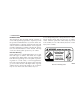
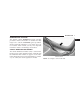
INTRODUCTION 5 Failure to use driver and passenger seat belts provided is a major cause of severe or fatal injury. In fact, the U.S. government notes that the universal use of existing seat belts could cut the highway death toll by 10,000 or more each year, and could reduce disabling injuries by 2 million annually. In a roll over crash an unbelted person is significantly more likely to die than a person wearing a seat belt. Always buckle up.
INTRODUCTION
INTRODUCTION 7 WARNINGS AND CAUTIONS This manual contains WARNINGS against operating procedures which could result in an accident or bodily injury. It also contains CAUTIONS against procedures which could result in damage to your vehicle. If you do not read this entire manual you may miss important information. Observe all Warnings and Cautions. VEHICLE IDENTIFICATION NUMBER The vehicle identification number (VIN) is found on the left front corner of the instrument panel, visible through the windshield.
INTRODUCTION VEHICLE MODIFICATIONS / ALTERATIONS WARNING! Any modifications or alterations to this vehicle could seriously affect its roadworthiness and safety and may lead to an accident resulting in serious injury or death.
THINGS TO KNOW BEFORE STARTING YOUR VEHICLE 2 CONTENTS 䡵 A Word About Your Keys . . . . . . . . . . . . . . . . . .12 䡵 Security Alarm System — If Equipped . . . . . . . . .17 ▫ Ignition Key Removal . . . . . . . . . . . . . . . . . . .12 ▫ To Set The Alarm . . . . . . . . . . . . . . . . . . . . . .18 ▫ Locking Doors With The Key . . . . . . . . . . . . . .13 ▫ To Disarm The System . . . . . . . . . . . . . . . . . . .18 䡵 Ignition And Steering Lock . . . . . . . . . . . . . . . . .
THINGS TO KNOW BEFORE STARTING YOUR VEHICLE ▫ General Information . . . . . . . . . . . . . . . . . . . .22 ▫ Window Lockout Switch . . . . . . . . . . . . . . . . .33 ▫ Programming Additional Transmitters . . . . . . . .23 䡵 Liftgate . . . . . . . . . . . . . . . . . . . . . . . . . . . . . . .34 ▫ Battery Replacement . . . . . . . . . . . . . . . . . . . .24 ▫ Power Liftgate — If Equipped . . . . . . . . . . . . .35 䡵 Remote Starting System — If Equipped . . . . . . . .
THINGS TO KNOW BEFORE STARTING YOUR VEHICLE 11 ▫ Driver And Right Front Passenger Supplemental Restraint System (SRS)—Airbags . . . . . . . . . . .51 ▫ Event Data Recorder (EDR) . . . . . . . . . . . . . . .60 ▫ Child Restraint . . . . . . . . . . . . . . . . . . . . . . . .62 䡵 Engine Break-In Recommendations . . . . . . . . . . .71 䡵 Safety Tips . . . . . . . . . . . . . . . . . . . . . . . . . . . .72 ▫ Exhaust System . . . . . . . . . . . . . . . . . . . . . . .
THINGS TO KNOW BEFORE STARTING YOUR VEHICLE A WORD ABOUT YOUR KEYS The dealer that sold you your new vehicle has the key code numbers for your vehicle locks. These numbers can be used to order duplicate keys from your dealer. Ask your dealer for these numbers and keep them in a safe place. Ignition Key Removal Automatic Transmission Place the shift lever in PARK. Turn the ignition switch to the LOCK position, and remove the key.
THINGS TO KNOW BEFORE STARTING YOUR VEHICLE 13 in the ignition cylinder. If this occurs, rotate the key to the right slightly, then remove the key as described. If a malfunction occurs, the system will trap the key in the ignition cylinder to warn you that this safety feature is inoperable. The engine can be started and stopped but the key cannot be removed until you obtain service. WARNING! Never leave children alone in a vehicle.
THINGS TO KNOW BEFORE STARTING YOUR VEHICLE inserted or withdrawn only in the LOCK position. Push in on the key in the ignition lock cylinder to rotate to the LOCK position. WARNING! The key cannot be turned to LOCK until the selector is in the PARK position. Do not attempt to pull the shift lever out of PARK after the key is in the LOCK position.
THINGS TO KNOW BEFORE STARTING YOUR VEHICLE 15 For vehicles equipped with the Electronic Vehicle Information Center (EVIC), the power window switches, radio, hands–free system (if equipped), and power outlets will remain active for up to 10 minutes after the ignition switch is turned off. Opening either front door will cancel this feature. The time for this feature is programmable.
THINGS TO KNOW BEFORE STARTING YOUR VEHICLE If the Vehicle Security Alarm Indicator Light turns on during normal vehicle operation (vehicle running for longer than 10 seconds), it indicates that there is a fault in the electronics. Should this occur, have the vehicle serviced as soon as possible. Replacement Keys NOTE: Only keys that have been programmed to the vehicle electronics can be used to start the vehicle.
THINGS TO KNOW BEFORE STARTING YOUR VEHICLE 17 4. Insert a blank Sentry Key into the ignition switch and turn the ignition switch ON within 60 seconds. After 10 seconds a single chime will sound and the Vehicle Theft Alarm Indicator Light will stop flashing, turn on again for 3 seconds, and then turn off. General Information The Sentry Key system complies with FCC rules part 15 and with RSS-210 of Industry Canada. Operation is subject to the following conditions: The new Sentry Key has been programmed.
THINGS TO KNOW BEFORE STARTING YOUR VEHICLE To Set the Alarm: The alarm will set when you use the power door locks or use the Keyless Entry transmitter to lock the doors. After all the doors are locked and closed the security light in the instrument cluster will flash rapidly to signal that the system is arming. The security light in the instrument panel cluster will flash rapidly for about 15 seconds to indicate that the alarm is being set.
THINGS TO KNOW BEFORE STARTING YOUR VEHICLE 19 ILLUMINATED ENTRY REMOTE KEYLESS ENTRY Vehicles Equipped With Power Door Locks All interior lights will illuminate in the vehicle when the doors are unlocked using the key fob. 2 The interior lights will remain on for 30 seconds after the last door is closed, or until all doors are closed and either the ignition is turned to the ON position or a key fob LOCK button is pressed.
THINGS TO KNOW BEFORE STARTING YOUR VEHICLE NOTE: Your vehicle’s keyfob may have three, four or five buttons (shown), depending on the optional features purchased with your vehicle. The system can be programmed to unlock all the doors upon the first UNLOCK button press by using the following procedure: This system allows you to lock or unlock the doors and liftgate or activate the panic alarm from distances a minimum of 66 feet (20 meters) using a hand held radio transmitter.
THINGS TO KNOW BEFORE STARTING YOUR VEHICLE 21 5. If the desired programming was not achieved or to reactivate this feature, repeat the above steps. To lock the doors and liftgate: Press and release the LOCK button on the key fob to lock all doors and liftgate. If the ignition is OFF, when the doors are locked, the parking lights will flash on once and the horn will chirp once. Horn Chirp Programming The horn chirp feature will be shipped from the assembly plants activated.
THINGS TO KNOW BEFORE STARTING YOUR VEHICLE 4. Test the flash lamps with LOCK feature while outside of the vehicle, by pressing the LOCK button on the key fob with the ignition in the OFF position, and the key removed. NOTE: Pressing the LOCK button on the key fob, while you are in the vehicle, will activate the Security Alarm. Opening a door with the Security Alarm activated will cause the alarm to sound. Press the UNLOCK button to deactivate the Security Alarm. 5.
THINGS TO KNOW BEFORE STARTING YOUR VEHICLE 23 NOTE: Changes or modifications not expressly approved by the party responsible for compliance could void the user’s authority to operate the equipment. NOTE: When entering program mode using that fob, all other programmed fobs will be erased and you will have to reprogram them for your vehicle. If your Remote Lock Control fails to operate from a normal distance, check for these two conditions.
THINGS TO KNOW BEFORE STARTING YOUR VEHICLE 7. When a single chime is heard release both buttons. The chime is an indication that you have successfully entered program mode. All fobs that are to be programmed must be done so within 60 seconds of when the chime was heard. 8. Using the fob to be programmed, press and release both the LOCK and UNLOCK buttons, simultaneously. 9. A single chime will be heard. 10. Within four seconds of hearing the chime, press and release the UNLOCK button on the fob. 11.
THINGS TO KNOW BEFORE STARTING YOUR VEHICLE 25 3. To assemble the transmitter case, snap the two halves together. 4. Replace screw if equipped. NOTE: If the key fob is equipped with a screw, reinstall and tighten the screw until snug. REMOTE STARTING SYSTEM — IF EQUIPPED Your vehicle may be equipped with a remote starting system, which will allow the vehicle to be started up to 300 feet away from the vehicle using the remote keyless entry key fob which is part of your ignition key.
THINGS TO KNOW BEFORE STARTING YOUR VEHICLE To remote start your vehicle, press the REMOTE START button on the key fob twice within three seconds. To indicate that the vehicle is about to start, the parking lights will flash and the horn will sound briefly. Once the vehicle has started, the engine will run for 15 minutes. To cancel remote start, press the REMOTE START button once.
THINGS TO KNOW BEFORE STARTING YOUR VEHICLE 27 The vehicle can be started remotely up to a maximum of two times. The vehicle is also allowed a maximum of one failed start, where the remote start sequence was initiated but cancelled before the engine begins to crank. After either of these conditions, or if the Vehicle Theft Alarm is alarming, or if the PANIC button was pressed, the vehicle must be reset by inserting a valid key into the ignition and moving it to the RUN position, then back to LOCK.
THINGS TO KNOW BEFORE STARTING YOUR VEHICLE Power Door Locks A power door lock switch is on each front door trim panel. Use this switch to lock or unlock the doors. locks will not operate. This prevents you from accidentally locking your keys in the vehicle. Removing the key or closing the door will allow the locks to operate. A chime will sound if the key is in the ignition switch and a door is open, as a reminder to remove the key.
THINGS TO KNOW BEFORE STARTING YOUR VEHICLE 29 3. Place the key into the ignition. 4. Within 10 seconds, cycle the key from the OFF position to the ON position a minimum of four times; ending in the ON position. (do not start the engine). 5. Within 30 seconds, press the driver’s door lock switch in the LOCK direction. 6. A single chime will be heard to indicate the feature has been disabled. 7. To re-activate this feature, repeat the above steps. 8.
THINGS TO KNOW BEFORE STARTING YOUR VEHICLE 5. Within 30 seconds, press the driver’s door lock switch in the UNLOCK direction. 6. A single chime will sound to indicate the feature has been changed. 7. Repeat the above steps to alternate the availability of this feature. 8. If a chime is not heard, program mode was canceled before the feature could be changed. If necessary repeat the above procedure.
THINGS TO KNOW BEFORE STARTING YOUR VEHICLE 31 WARNING! Avoid trapping anyone in a vehicle in a collision. Remember that the rear doors can only be opened from the outside when the child protection locks are engaged. WINDOWS Power Windows 2 NOTE: After setting the child protection door lock system, always test the door from the inside to make certain it is in the desired position.
THINGS TO KNOW BEFORE STARTING YOUR VEHICLE windows will operate only when the ignition switch is turned to the ON position and for ten minutes after the ignition is turned OFF or the driver’s door is opened. This feature can be turned off by your authorized dealer. NOTE: The Power Accessory Delay feature will allow the power windows to operate for ten minutes after the ignition it turned OFF. WARNING! Never leave children alone in a vehicle.
THINGS TO KNOW BEFORE STARTING YOUR VEHICLE 33 NOTE: If the window runs into any obstacle during the auto-closure it will reverse direction and then stop. Remove the obstacle and use the window switch again to close the window. Any impact due to rough road conditions may trigger the auto reverse function unexpectedly during auto closure. If this happens pull the switch lightly to the first detent and hold to close the window manually.
THINGS TO KNOW BEFORE STARTING YOUR VEHICLE LIFTGATE The liftgate can be unlocked using the remote keyless entry transmitter or by activating the power door lock switches located on the front doors. NOTE: When the engine is running from a Remote Start (if equipped), the vehicle must first be unlocked by pressing the remote transmitter UNLOCK button prior to activating the Power Liftgate otherwise the engine will stop automatically.
THINGS TO KNOW BEFORE STARTING YOUR VEHICLE 35 The liftgate will not manually open if the vehicle is in gear or the vehicle speed is above 0 mph (0 km/h). NOTE: • If the liftgate is locked and is not equipped with a powered liftgate, pressing the button on the remote keyless entry transmitter will result in the liftgate becoming unlocked for 30 seconds allowing you to manually access the liftgate area. The liftgate will re-lock automatically within 10 seconds once the liftgate is closed.
THINGS TO KNOW BEFORE STARTING YOUR VEHICLE NOTE: • In the event of a power malfunction to the liftgate, an emergency liftgate latch release can be used to open the liftgate. The emergency liftgate latch release can be accessed through a snap-in cover located on the liftgate trim panel. WARNING! During power operation, personal injury or cargo damage may occur. Ensure the liftgate travel path is clear. Make sure the liftgate is closed and latched before driving away.
THINGS TO KNOW BEFORE STARTING YOUR VEHICLE 37 • The power liftgate must be in the full open position for any of the buttons to operate. If the liftgate is not fully open, press the remote keyless entry transmitter or overhead console button to fully open the liftgate and then press again to close. • The power liftgate will not operate in temperatures below ⫺22° F (⫺30° C) or temperatures above 150° F (65° C).
THINGS TO KNOW BEFORE STARTING YOUR VEHICLE WARNING! • Driving with the liftgate open can allow poisonous exhaust gases into your vehicle. You and your passengers could be injured by these fumes. Keep the liftgate closed when you are operating the vehicle. • If you are required to drive with the liftgate open, make sure that all windows are closed, and the climate control blower switch is set at high speed. DO NOT use the recirculation mode. Gas props support the liftgate in the open position.
THINGS TO KNOW BEFORE STARTING YOUR VEHICLE 39 WARNING! In a collision, you and your passengers can suffer much greater injuries if you are not properly buckled up. You can strike the interior of your vehicle or other passengers, or you can be thrown out of the vehicle. Always be sure you and others in your vehicle are buckled up properly. Buckle up even though you are an excellent driver, even on short trips. Someone on the road may be a poor driver and cause a collision that includes you.
THINGS TO KNOW BEFORE STARTING YOUR VEHICLE WARNING! WARNING! It is extremely dangerous to ride in a cargo area, inside or outside of a vehicle. In a collision, people riding in these areas are more likely to be seriously injured or killed. Do not allow people to ride in any area of your vehicle that is not equipped with seats and seat belts. Be sure everyone in your vehicle is in a seat and using a seat belt properly. • Wearing a seat belt incorrectly is dangerous.
THINGS TO KNOW BEFORE STARTING YOUR VEHICLE 41 Lap/Shoulder Belt Operating Instructions 1. Enter the vehicle and close the door. Sit back and adjust the seat. Pulling Out Belt and Latchplate 2. The seat belt latch plate is above the back of the front seat, next to your arm in the rear seat. Grasp the latch plate and pull out the belt. Slide the latch plate up the webbing as far as necessary to allow the belt to go around your lap. Removing Slack From Belt 3.
THINGS TO KNOW BEFORE STARTING YOUR VEHICLE WARNING! • A belt buckled into the wrong buckle will not protect you properly. The lap portion could ride too high on your body, possibly causing internal injuries. Always buckle your belt into the buckle nearest you. • A belt that is too loose will not protect you as well. In a sudden stop you could move too far forward, increasing the possibility of injury. Wear your seat belt snugly. • A belt that is worn under your arm is very dangerous.
THINGS TO KNOW BEFORE STARTING YOUR VEHICLE 43 WARNING! • A lap belt worn too high can increase the risk of internal injury in a collision. The belt forces won’t be at the strong hip and pelvic bones, but across your abdomen. Always wear the lap belt as low as possible and keep it snug. • A twisted belt can’t do its job as well. In a collision it could even cut into you. Be sure the belt is straight. If you can’t straighten a belt in your vehicle, take it to your dealer and have it fixed. 5.
THINGS TO KNOW BEFORE STARTING YOUR VEHICLE Adjustable Upper Shoulder Belt Anchorage In the front and second row outboard seats, the shoulder belt can be adjusted upward or downward to help position the belt away from your neck. Push in on the anchorage release button to release the anchorage, and then move it up or down to the position that serves you best.
THINGS TO KNOW BEFORE STARTING YOUR VEHICLE 45 WARNING! A 20% seatback that is not fully latched in the upright position will not protect you properly. Second Row Center Seat Belt The center seating position in the second row has a seat belt assembly that can be converted from the normal emergency locking mode to the automatic locking mode. The seat belt should only be used in the automatic locking mode when a child seat is installed at this seating location.
THINGS TO KNOW BEFORE STARTING YOUR VEHICLE Rear 60/40 Seat Third Row Center Three Point Belt — If Equipped The center three point seat belt for the third row rear seat may be disconnected to allow the 60% seat back to easily fold down. The keyed-buckle latch plate (small latch plate at the end of the belt) can be detached from the keyed seat belt buckle (buckle without a red release button) located on the left inboard side of the third row bench seat.
THINGS TO KNOW BEFORE STARTING YOUR VEHICLE 47 2 Third Row Center Seat Belt To reattach the seat belt to the third row center seat, pull the small (keyed buckle) latch plate forward from the headliner slots and insert it into the keyed buckle until there is an audible click. Refer to the previous section for the proper seat belt usage.
THINGS TO KNOW BEFORE STARTING YOUR VEHICLE occupant early in a collision. Pretensioners work for all size occupants, including those in child restraints. NOTE: These devices are not a substitute for proper seat belt placement by the occupant. The seat belt still must be worn snugly and positioned properly. The pretensioners are triggered by the Occupant Restraint Controller (ORC). Like the airbags, the pretensioners are single use items.
THINGS TO KNOW BEFORE STARTING YOUR VEHICLE 49 Enhanced Warning System (BeltAlert) will continue to chime and flash the Seat Belt Warning Light for 96 seconds or until the driver’s seat belt is buckled. The Enhanced Warning System (BeltAlert) will be reactivated if the driver’s seat belt is unbuckled for more than 10 seconds and the vehicle speed is greater than 5 mph (8 km/h). Once the warning is triggered it can be paused if the vehicle speed drops below 5 mph (8 km/h.
THINGS TO KNOW BEFORE STARTING YOUR VEHICLE 4. Programming mode will be cancelled after the feature has toggled with the seat belt still buckled or if the ignition switch is turned to the lock position or 10 seconds after the feature has toggled. The Enhanced Warning System (BeltAlert) can be reactivated by repeating this procedure.
THINGS TO KNOW BEFORE STARTING YOUR VEHICLE 51 Driver And Right Front Passenger Supplemental Restraint System (SRS)—Airbags the instrument panel, above the glove compartment. The words SRS/AIRBAG are embossed on the airbag covers. NOTE: The front airbags are certified to the Federal regulations that allow less forceful deployment. The front airbags have a multistage inflator design. This may allow the airbag to have different rates of inflation that are based on collision severity and occupant size.
THINGS TO KNOW BEFORE STARTING YOUR VEHICLE WARNING! • Do not put anything on or around the front airbag covers or attempt to manually open them. You may damage the airbags and you could be injured because the airbags are no longer functional. These protective covers for the airbag cushions are designed to open only when the airbags are inflating. • Your vehicle is equipped with window bags, do not stack luggage or other cargo up high enough to block the location of the window bag.
THINGS TO KNOW BEFORE STARTING YOUR VEHICLE 53 Here are some simple steps you can follow to minimize the risk of harm from a deploying airbag. 1. Children 12 years and under should always ride buckled up in a rear seat in an appropriate child restraint. Infants in rear-facing child restraints should NEVER ride in the front seat of a vehicle with a passenger front airbag. An airbag deployment can cause severe injury or death to infants in that position.
THINGS TO KNOW BEFORE STARTING YOUR VEHICLE WARNING! • Relying on the airbags alone could lead to more severe injuries in a collision. The airbags work with your seat belt to restrain you properly. In some collisions the airbags won’t deploy at all. Always wear your seat belts even though you have airbags. • Being too close to the steering wheel or instrument panel during airbag deployment could cause serious injury. Airbags need room to inflate.
THINGS TO KNOW BEFORE STARTING YOUR VEHICLE 55 How the Airbag System Works • The Occupant Restraint Controller (ORC) determines if a frontal collision is severe enough to require the airbags to inflate. The front airbag inflators are designed to provide different rates of airbag inflation from direction provided by the ORC. The ORC will not detect roll over. The ORC also monitors the readiness of the electronic parts of the system whenever the ignition switch is in the START or RUN positions.
THINGS TO KNOW BEFORE STARTING YOUR VEHICLE • The Driver and Passenger Airbag/Inflator Units are located in the center of the steering wheel and the right side of the instrument panel. When the ORC detects a collision requiring the airbags, it signals the inflator units. A large quantity of nontoxic gas is generated to inflate the front airbags. Different airbag inflation rates may be possible based on collision severity.
THINGS TO KNOW BEFORE STARTING YOUR VEHICLE 57 The following requirements must be strictly adhered to: • Do not modify the front seat center console or center position seat in any way. • Do not use prior or future model year seat covers not designated for the specific model being repaired. Always use the correct seat cover specified for the vehicle. • Do not replace the seat cover with an aftermarket seat cover. • Do not add a secondary seat cover other than those approved by DaimlerChrysler/Mopar.
THINGS TO KNOW BEFORE STARTING YOUR VEHICLE However, if you haven’t healed significantly within a few days, or if you have any blistering, see your doctor immediately. As the airbags deflate you may see some smoke-like particles. The particles are a normal byproduct of the process that generates the nontoxic gas used for airbag inflation. These airborne particles may irritate the skin, eyes, nose, or throat. If you have skin or eye irritation, rinse the area with cool water.
THINGS TO KNOW BEFORE STARTING YOUR VEHICLE 59 Maintaining Your Airbag System WARNING! • • • • Modifications to any part of the airbag system could cause it to fail when you need it. You could be injured if the airbag system is not there to protect you. Do not modify the components or wiring, including adding any kind of badges or stickers to the steering wheel hub trim cover or the upper right side of the instrument panel.
THINGS TO KNOW BEFORE STARTING YOUR VEHICLE • The light flickers or comes on and remains on while driving. NOTE: If the speedometer, tachometer or any engine related gauges are not working, the airbag control module may also be disabled. The airbags may not be ready to inflate for your protection. Promptly check fuse block for blown fuses. Refer to the label located on the inside of the fuse block cover for the proper airbag fuses. See your dealer if the fuse is good.
THINGS TO KNOW BEFORE STARTING YOUR VEHICLE 61 may be released for incorporation in aggregate crash databases, such as those maintained by the US government and various states. Data of a potentially sensitive nature, such as would identify a particular driver, vehicle, or crash, will be treated confidentially. Confidential data will not be disclosed by DaimlerChrysler Corporation to any third party except when: 1.
THINGS TO KNOW BEFORE STARTING YOUR VEHICLE Child Restraint Everyone in your vehicle needs to be buckled up all the time - babies and children, too. Every state in the United States and all Canadian provinces require that small children ride in proper restraint systems. This is the law, and you can be prosecuted for ignoring it. Children 12 years and under should ride properly buckled up in a rear seat, if available.
THINGS TO KNOW BEFORE STARTING YOUR VEHICLE 63 LATCH child restraint anchorage system. (See the LATCH - Child Seat Anchorage System section.) • Rearward-facing child seats must NEVER be used in the front seat of a vehicle with a front passenger airbag. An airbag deployment could cause severe injury or death to infants in this position. Older Children and Child Restraints Children who weigh more than 20 lbs (9 kg) and who are older than one year can ride forward-facing in the vehicle.
THINGS TO KNOW BEFORE STARTING YOUR VEHICLE • If the shoulder belt contacts the face or neck, move the child closer to the center of the vehicle. Never allow a child to put the shoulder belt under an arm. WARNING! • Improper installation can lead to failure of an infant or child restraint. It could come loose in a collision. The child could be badly injured or killed. Follow the manufacturer’s directions exactly when installing an infant or child restraint.
THINGS TO KNOW BEFORE STARTING YOUR VEHICLE 65 around the child restraint so that it is not necessary to use a locking clip. If the seat belt has a cinching latch plate, pulling up on the shoulder portion of the lap/shoulder belt will tighten the belt. The cinching latch plate will keep the belt tight, however, any seat belt system will loosen with time, so check the belt occasionally and pull it tight if necessary. If the seat belt has a automatic locking retractor, it will have a distinctive label.
THINGS TO KNOW BEFORE STARTING YOUR VEHICLE and hooks for connection to the top tether anchorages have been available for some time. For some older child restraints, many child restraint manufacturers offer add-on tether strap kits or retro-fit kits. You are urged to take advantage of all the available attachments provided with your child restraint in any vehicle.
THINGS TO KNOW BEFORE STARTING YOUR VEHICLE 67 Second Row Seat Right Side Installing the LATCH-Compatible Child Restraint System We urge that you carefully follow the directions of the manufacturer when installing your child restraint. Not all child restraint systems will be installed as described here. Again, carefully follow the installation instructions that were provided with the child restraint system.
THINGS TO KNOW BEFORE STARTING YOUR VEHICLE anchorages. Next attach the lower hooks or connectors over the top of the anchorage bars, pushing aside the seat cover material. Then attach the tether strap to the anchorage located on the back of the seat, being careful to route the tether strap to provide the most direct path between the anchor and the child restraint.
THINGS TO KNOW BEFORE STARTING YOUR VEHICLE 69 Installing Child Restraints Using the Vehicle Seat Belt The second and third row seats have either cinching latch plates or automatic locking retractors which are designed to keep the lap portion tight around the child restraint so that it is not necessary to use a locking clip. If the seat belt has a cinching latch plate, pulling up on the shoulder portion of the lap/shoulder belt will tighten the belt.
THINGS TO KNOW BEFORE STARTING YOUR VEHICLE WARNING! An incorrectly anchored tether strap could lead to increased head motion and possible injury to the child. Use only the anchor positions directly behind the child seat to secure a child restraint top tether strap. Children and infants are safer when properly restrained in a child restraint system secured in a rear seating position.
THINGS TO KNOW BEFORE STARTING YOUR VEHICLE 71 WARNING! An incorrectly anchored tether strap could lead to seat failure and injury to the child. In a collision, the seat could come loose and allow the child to crash into the inside of the vehicle or other passengers, or even be thrown from the vehicle. Use only the anchor positions directly behind the child seat to secure a child restraint top tether strap. Follow the instructions for Child Restraint Tether Anchor in this section.
THINGS TO KNOW BEFORE STARTING YOUR VEHICLE A new engine may consume some oil during its first few thousand miles of operation. This is a normal part of the break-in and is not an indication of difficulty. SAFETY TIPS Exhaust System WARNING! Exhaust gases contain carbon monoxide, an extremely toxic gas that by itself is colorless and odorless.
THINGS TO KNOW BEFORE STARTING YOUR VEHICLE 73 Safety Checks You Should Make Inside The Vehicle Heater Defroster Ducts Inspect the heater defroster ducts for proper operation. Check for proper air flow through all defroster ducts. If there are any question regarding the operation of your heater defroster ducts, have the system checked by an authorized dealer Seat Belts Inspect the belt system periodically, checking for cuts, frays and loose parts. Damaged parts must be replaced immediately.
THINGS TO KNOW BEFORE STARTING YOUR VEHICLE Lights Check the operation of all exterior lights. Check turn signal and high beam indicator lights on the instrument panel. Door Latches Check for positive closing, latching and locking. Fluid Leaks Check area under vehicle after overnight parking for fuel, water, oil, or other fluid leaks. Also, if fuel fumes are detected the cause should be located and corrected.
UNDERSTANDING THE FEATURES OF YOUR VEHICLE CONTENTS 䡵 Mirrors . . . . . . . . . . . . . . . . . . . . . . . . . . . . . . .79 ▫ Inside Day/Night Mirror . . . . . . . . . . . . . . . . .79 ▫ Automatic Dimming Mirror — If Equipped . . . .80 ▫ Outside Mirrors . . . . . . . . . . . . . . . . . . . . . . .81 ▫ Exterior Mirrors Folding Feature — If Equipped . . . . . . . . . . . . . . . . . . . . . . . . . .81 ▫ Electric Remote-Control Mirrors . . . . . . . . . . . .81 ▫ Illuminated Vanity Mirrors — If Equipped .
UNDERSTANDING THE FEATURES OF YOUR VEHICLE 䡵 Seats . . . . . . . . . . . . . . . . . . . . . . . . . . . . . . . . 108 ▫ Third Row Seat Bench — If Equipped . . . . . . . 120 ▫ Front Seat Manual Seat Adjustment . . . . . . . . 108 ▫ Third Row 60/40 Folding — If Equipped . . . . 123 ▫ Front Seats Manual Seat Recliners . . . . . . . . . . 109 䡵 Driver Memory System — If Equipped . . . . . . . 125 ▫ Manual Lumbar Support Adjustment — If Equipped . . . . . . . . . . . . . . . . . . . . . . . . .
UNDERSTANDING THE FEATURES OF YOUR VEHICLE 77 ▫ Headlight Delay . . . . . . . . . . . . . . . . . . . . . . 133 ▫ Adjustment . . . . . . . . . . . . . . . . . . . . . . . . . 141 ▫ Automatic Headlights — If Equipped . . . . . . . 133 䡵 Electronic Speed Control — If Equipped . . . . . . 142 ▫ Headlights, Parking Lights, Panel Lights . . . . . 134 ▫ To Activate . . . . . . . . . . . . . . . . . . . . . . . . . . 143 ▫ Illuminated Entry . . . . . . . . . . . . . . . . . . . . .
UNDERSTANDING THE FEATURES OF YOUR VEHICLE ▫ Dome/Reading Lights . . . . . . . . . . . . . . . . . . 151 ▫ Express Open Feature . . . . . . . . . . . . . . . . . . 167 ▫ Electronic Vehicle Information Center (EVIC) — If Equipped . . . . . . . . . . . . . . . . . . . . . . . . . 152 ▫ Wind Buffeting . . . . . . . . . . . . . . . . . . . . . . . 168 ▫ Compass/Temperature Button . . . . . . . . . . . . 158 䡵 Garage Door Opener — If Equipped . . . . . . . . . 160 ▫ Programming HomeLink . . . . . . . . .
UNDERSTANDING THE FEATURES OF YOUR VEHICLE 79 MIRRORS Inside Day/Night Mirror The mirror should be adjusted to center on the view through the rear window. A two-point pivot system allows for horizontal and vertical adjustment of the mirror. Day/Night Mirror Annoying headlight glare can be reduced by moving the small control under the mirror to the night position (toward rear of truck). The mirror should be adjusted while set in the day position (toward windshield).
UNDERSTANDING THE FEATURES OF YOUR VEHICLE Automatic Dimming Mirror — If Equipped This mirror will automatically adjust for annoying headlight glare from vehicles behind you. You can turn the feature on or off by pressing the button at the base of the mirror. A light in the button will indicate when the dimming feature is activated. This option also controls the driver side mirror when it is equipped with auto dimming glass.
UNDERSTANDING THE FEATURES OF YOUR VEHICLE 81 CAUTION! To avoid damage to the mirror during cleaning, never spray any cleaning solution directly onto the mirror. Apply the solution onto a clean cloth and wipe the mirror clean. Electric Remote-Control Mirrors The controls for the power mirrors are located on the driver’s door trim panel.
UNDERSTANDING THE FEATURES OF YOUR VEHICLE WARNING! Vehicles and other objects seen in the right side convex mirror will look smaller and farther away than they really are. Relying too much on your right side mirror could cause you to collide with another vehicle or other object. Use your inside mirror when judging the size or distance of a vehicle seen in the right side mirror. Mirror Directions To adjust a mirror, turn the control wand toward the left or right mirror positions indicated.
UNDERSTANDING THE FEATURES OF YOUR VEHICLE 83 Automatic Dimming Driver’s Exterior Mirror — If Equipped This mirror will automatically adjust for annoying light glare from vehicles behind you. This feature is controlled by the inside mirror and can be turned off by pressing the button at the base of the inside mirror. Lighted Vanity Mirror Heated Mirrors — If Equipped Heated mirrors are automatically activated when you depress the rear window defroster switch located on the instrument panel.
UNDERSTANDING THE FEATURES OF YOUR VEHICLE NOTE: The UConnect™ system use requires a cellular phone equipped with the Bluetooth ⬙Hands-Free Profile,⬙ version 0.96 or higher. See www.chrysler.com/uconnect for supported phones. UConnect™ allows you to transfer calls between the system and your cellular phone as you enter or exit your vehicle, and enables you to mute the system’s microphone for private conversation. The UConnect™ phonebook enables you to store up to 32 names and four numbers per name.
UNDERSTANDING THE FEATURES OF YOUR VEHICLE 85 Headset Profile), you may not be able to use any UConnect™ features. Refer to your cellular service provider or the phone manufacturer for details. The UConnect™ system is fully integrated with the vehicle’s audio system. The volume of the UConnect™ system can be adjusted either from the radio volume control knob, or from the steering wheel radio control (right switch), if so equipped.
UNDERSTANDING THE FEATURES OF YOUR VEHICLE • Prior to giving a voice command, one must wait for the voice on beep, which follows the ⬙Ready⬙ prompt or another prompt. • For certain operations, compound commands can be used. For example, instead of saying ⬙Setup⬙ and then ⬙Phone Pairing,⬙ the following compound command can be said: ⬙Setup Phone Pairing.⬙ • For each feature explanation in this section, only the combined form of the voice command is given.
UNDERSTANDING THE FEATURES OF YOUR VEHICLE 87 Pair (Link) UConnect™ System to a Cellular Phone To begin using your UConnect™ system, you must pair your compatible Bluetooth™ enabled cellular phone. NOTE: The UConnect™ system use requires a cellular phone equipped with the Bluetooth ⬙Hands-Free Profile,⬙ version 0.96 or higher. See www.chrysler.com/uconnect for supported phones. To complete the pairing process, you will need to reference your cellular phone owner’s manual.
UNDERSTANDING THE FEATURES OF YOUR VEHICLE • You will then be asked to give your cellular phone a priority level between 1 and 7, 1 being the highest priority. You can pair up to seven cellular phones to your UConnect™ system. However, at any given time, only one cellular phone can be in use, connected to your UConnect™ System. The priority allows the UConnect™ system to know which cellular phone to use if multiple cellular phones are in the vehicle at the same time.
UNDERSTANDING THE FEATURES OF YOUR VEHICLE 89 Call/Dial by Saying a Name Add Names to Your UConnect™ Phonebook • Press the “Phone” button to begin. NOTE: Adding names to phonebook is recommended when vehicle is not in motion. • After the ⬙Ready⬙ prompt and the following beep, say “Dial” or Call.⬙ • Press the “Phone” button to begin. • System will prompt you to say the name of the person you want call. • After the ⬙Ready⬙ prompt and the following beep, say ⬙Phonebook New Entry.
UNDERSTANDING THE FEATURES OF YOUR VEHICLE After you are finished adding an entry into the phonebook, you will be given the opportunity to add more phone numbers to the current entry or to return to the main menu. • You will then be asked for the name of the phonebook entry that you wish to edit. The UConnect™ system will allow you to enter up to 32 names in the phonebook with each name having up to four associated phone numbers and designations.
UNDERSTANDING THE FEATURES OF YOUR VEHICLE 91 Delete Entries in the UConnect™ Phonebook NOTE: Editing phonebook entries is recommended when vehicle is not in motion. • Press the ’Phone’ button to begin. • After the ⬙Ready⬙ prompt and the following beep, say ⬙Phonebook Delete.⬙ • After you enter the Phonebook Delete menu, you will then be asked for the name of the entry that you wish to delete.
UNDERSTANDING THE FEATURES OF YOUR VEHICLE List All Names in the UConnect™ Phonebook • Press the ’Phone’ button to begin. • After the ⬙Ready⬙ prompt and the following beep, say ⬙Phonebook List Names.⬙ • The UConnect™ system will play the names of all the phonebook entries. • To call one of the names in the list, press the ⬙Voice Recognition’ button during the playing of the desired name, and then say ⬙Call.⬙ NOTE: the user can also exercise ⬙Edit⬙ or ⬙Delete⬙ operations at this point.
UNDERSTANDING THE FEATURES OF YOUR VEHICLE 93 Answer or Reject an Incoming Call - Call Currently in Progress If a call is currently in progress and you have another incoming call, you will hear the same network tones for call waiting that you normally hear when using your cell phone. Press the ’Phone’ button to place the current call on hold and answer the incoming call. NOTE: The UConnect™ system compatible phones in market today do not support rejecting an incoming call when another call is in progress.
UNDERSTANDING THE FEATURES OF YOUR VEHICLE Conference Call When two calls are in progress (one active and one on hold), press and hold the ’Phone’ button until you hear a double beep indicating that the two calls have been joined into one conference call. Redial Three-Way Calling To initiate three-way calling, press the ’Voice Recognition’ button while a call is in progress and make a second phone call as described under ⬙Making a Second Call while Current Call in Progress.
UNDERSTANDING THE FEATURES OF YOUR VEHICLE 95 • After ignition key is switched to off, a call can continue on the UConnect™ system for certain duration, after which the call is automatically transferred from the UConnect™ system to the mobile phone. • An active call is automatically transferred to the mobile phone after ignition key is switched to off. UConnect™ System Features Language Selection To change the language that the UConnect™ system is using, • Press the ’Phone’ button to begin.
UNDERSTANDING THE FEATURES OF YOUR VEHICLE • After the ⬙Ready⬙ prompt and the following beep, say ⬙Emergency⬙ and the UConnect™ system will instruct the paired cellular phone to call the emergency number. This feature is only supported in the USA. NOTE: The emergency number dialed is based on the Country where the vehicle is purchased (911 for USA and Canada and 060 for Mexico). The number dialed may not be applicable with the available cellular service and area.
UNDERSTANDING THE FEATURES OF YOUR VEHICLE 97 Paging To learn how to page, refer to ⬙Working with Automated Systems.⬙ Paging works properly except for pagers of certain companies which time-out a little too soon to work properly with the UConnect™ system. Voice Mail Calling To learn how to access your voice mail, refer to ⬙Working with Automated Systems.
UNDERSTANDING THE FEATURES OF YOUR VEHICLE Turning Confirmation Prompts On/Off Turning confirmation prompts off will stop the system from confirming your choices (e.g., the UConnect™ system will not repeat a phone number before you dial it). • Press the ’Phone’ button to begin. • After the ⬙Ready⬙ prompt and the following beep, say ⬙Setup Confirmations.⬙ The UConnect™ system will play the current confirmation prompt status and you will be given the choice to change it.
UNDERSTANDING THE FEATURES OF YOUR VEHICLE 99 Mute/Un-mute (Mute off) When you mute the UConnect™ system, you will still be able to hear the conversation coming from the other party, but the other party will not be able to hear you. In order to mute the UConnect™ system: Information Service When using AT&T Wireless Service, dialing to phone number ⬙#121,⬙ you can access voice activated automated system to receive news, weather, stocks, traffic, etc. related information.
UNDERSTANDING THE FEATURES OF YOUR VEHICLE If you would like to connect or disconnect the Bluetooth™ connection between a UConnect™ paired cellular phone and the UConnect™ system, then follow the instruction described in your cellular phone user’s manual. Select another Cellular Phone This feature allows you to select and start using another phone with the UConnect™ system. The phone must have been previously paired to the UConnect™ system that you want to use it with.
UNDERSTANDING THE FEATURES OF YOUR VEHICLE 101 Delete UConnect™ Paired Cellular Phones • Press the ’Phone’ button to begin. • After the ⬙Ready⬙ prompt and the following beep, say ⬙Setup Phone Pairing.⬙ • At the next prompt, say ⬙Delete⬙ and follow the prompts. • You can also press the ⬘Voice Recognition’ button anytime while the list is being played and then choose the phone you wish to delete.
UNDERSTANDING THE FEATURES OF YOUR VEHICLE Voice Recognition (VR) • Always wait for the beep before speaking. • Speak normally, without pausing, just as you would speak to a person sitting approximately eight (8) feet away from you. • Make sure that no one other than you is speaking during a voice recognition period. • Performance is maximized under: • low-to-medium blower setting, • low-to-medium vehicle speed, • low road noise, • smooth road surface, • fully closed windows, • dry weather condition.
UNDERSTANDING THE FEATURES OF YOUR VEHICLE 103 • Even though international dialing for most number combinations is supported, some shortcut dialing number combinations may not be supported. • Performance, such as audio clarity, echo, and loudness to a large degree rely on the phone and network, and not the UConnect™ system. Far End Audio Performance • Echo at far end can sometime be reduced by lowering the in-vehicle audio volume.
UNDERSTANDING THE FEATURES OF YOUR VEHICLE
UNDERSTANDING THE FEATURES OF YOUR VEHICLE 105 3
UNDERSTANDING THE FEATURES OF YOUR VEHICLE
UNDERSTANDING THE FEATURES OF YOUR VEHICLE 107 Primary zero one two three four five six seven eight nine star (*) plus (+) pound (#) add location all Voice Commands Alternate(s) call cancel confirmation prompts continue delete dial edit emergency English erase all Espanol Fancais help home language list names list phones 3
UNDERSTANDING THE FEATURES OF YOUR VEHICLE mobile mute mute off new entry no pager pair a phone phone pairing phonebook previous record again redial return to main menu select phone send set up towing assistance transfer call try again voice training work yes pairing phone book return or main menu select phone settings or phone set up SEATS Front Seat Manual Seat Adjustment The adjusting lever is at the front of the seat, near the floor. Lift the lever and move the seat to the desired position.
UNDERSTANDING THE FEATURES OF YOUR VEHICLE 109 WARNING! Adjusting a seat while the vehicle is moving is dangerous. The sudden movement of the seat could cause you to lose control. The seat belt might not be properly adjusted and you could be injured. Adjust any seat only while the vehicle is parked. Manual Seat Adjuster Front Seats Manual Seat Recliners The bucket seats are equipped with recliners.
UNDERSTANDING THE FEATURES OF YOUR VEHICLE WARNING! Do not ride with the seatback reclined so that the shoulder belt is no longer resting against your chest. In a collision you could slide under the seat belt and be seriously or even fatally injured. Use the recliner only when the vehicle is parked. Manual Lumbar Support Adjustment — If Equipped The manual lumbar support adjustment lever is located on the right side of the driver seat and on the left side of the passenger’s seat.
UNDERSTANDING THE FEATURES OF YOUR VEHICLE 111 To lower the head restraint, depress the release button located at the base of the head restraint and push down on the head restraint. 8 - Way Driver’s Power Seat — If Equipped The driver power seat switches are located on the left side of the driver seat lower side trim. The bottom switch controls up/down, forward/rearward, and tilt adjustment. The top switch controls the seatback recline adjustment.
UNDERSTANDING THE FEATURES OF YOUR VEHICLE 4 - Way Passenger’s Power Seat — If Equipped The front passenger’s power seat switches are located on the right side of the passenger seat lower side trim. The bottom switch controls forward/rearward adjustment. The top switch controls the seatback recline adjustment. NOTE: The 4 - way seat does not have an up/down adjustment. Heated Seats — If Equipped This feature heats the driver, front passenger and second row seats.
UNDERSTANDING THE FEATURES OF YOUR VEHICLE 113 With the ignition switch in the RUN position, depressing the heated seat switch rocker to its momentary high or low position provides power to the heated seat element and maintains the requested temperature setting. If the heated seat switch is depressed to a different position (low or high) than the currently selected state, the requested temperature setting will change to a new selection.
UNDERSTANDING THE FEATURES OF YOUR VEHICLE off. Both of the indicators on identifies High heat level. The lower indicator on only, identifies Low heat level. WARNING! NOTE: The high heat setting will operate for approximately 30 minutes. After 30 minutes, the system will automatically transition to the low heat setting. The low heat setting will operate for 30 minutes, then the system will turn off.
UNDERSTANDING THE FEATURES OF YOUR VEHICLE 115 Second Row Bucket Seats — Fold and Tumble Second row bucket seats have seatback recliners on both seating positions. Raising the lever allows the seatback to be reclined an additional 11 degrees. 3. Pull up on the seatback release lever located on the outboard side of the seat and push the seatback forward. The second row bucket seats can be folded and tumbled forward for easy access to the third seat or rear cargo area.
UNDERSTANDING THE FEATURES OF YOUR VEHICLE 4. Pull up on the release handle and lift to tumble the seat fully forward. If the seat contacts the rear of the front seat, move the front seat forward. To relatch the seat, tilt the seat rearward and push down firmly to engage the rear attachments. Then lift the seatback release lever and pull the seatback up to return it to its full upright position.
UNDERSTANDING THE FEATURES OF YOUR VEHICLE 117 WARNING! In a collision, you or others in your vehicle could be injured if seats are not properly latched to their floor attachments. Always be sure the seats are fully latched. Tumble Lever Second Row 40/20/40 Seat — Fold and Tumble The 40/20/40 seat configuration is standard on all models. This seat is equipped with a unique fold-and-tumble feature. The 40% seatbacks have spring loaded hinges which assist with the folding of the seatbacks.
UNDERSTANDING THE FEATURES OF YOUR VEHICLE Second row leather seats have seatback recliners at the 40% seating positions. Raising the lever allows the seatback to be reclined an additional 11 degrees. be folded into the down position for use as a cargo floor, or the seat can now be tumbled forward to allow access to the rear of the vehicle. To fold the 20% seatback, pull the strap forward to release the seatback. Fold the seatback down for use as an armrest or to carry cargo.
UNDERSTANDING THE FEATURES OF YOUR VEHICLE 119 To Tumble the 40% seat, fully raise the lever on the side of the seat to release the floor latches and tumble the seat. WARNING! Do not drive the vehicle with the outer 40% second row seats in the tumbled position. The outer 40% second row seats are only intended to be tumbled for entry and exit to the third row seat. Failure to follow these instructions could result in personal injury.
UNDERSTANDING THE FEATURES OF YOUR VEHICLE NOTE: The seatback must be fully folded into the down position to allow the lever to be raised enough to release the floor latches. To Fold and Tumble the 2nd row 40% seats from the 3rd row, fully raise the lever at the rear of the seat to fold the seatback. Continue raising the lever to release the floor latches to tumble the seat. NOTE: The head restraints must be lowered but do not have to be removed to fold and tumble the seats.
UNDERSTANDING THE FEATURES OF YOUR VEHICLE 121 3 Seat Cushion Pockets Seat Cushion Movement Up And Forward
UNDERSTANDING THE FEATURES OF YOUR VEHICLE NOTE: The seat belt buckles are hinged to fold with the seat back. WARNING! Rear Seat Folded CAUTION! When loading cargo into the rear of you vehicle with the 3rd row seat folded flat, be careful not to damage the material on the head restraints. Do not sit in the third row seat unless the cushion and back are properly engaged. Proper engagement can be verified by pushing/pulling on the upright seatback. The seatback will not move unless properly engaged.
UNDERSTANDING THE FEATURES OF YOUR VEHICLE 123 Third Row 60/40 Folding — If Equipped 3 Third Row Seat 40% Seatback Fold Third Row Seat
UNDERSTANDING THE FEATURES OF YOUR VEHICLE Third Row Seat Features Third Row Seat Folded Forward
UNDERSTANDING THE FEATURES OF YOUR VEHICLE 125 preset settings. Your Remote Keyless Entry transmitters can also be programmed to recall the same positions when the UNLOCK button is pressed.
UNDERSTANDING THE FEATURES OF YOUR VEHICLE Setting Memory Positions and Linking Remote Keyless Entry Transmitter to Memory 5. Press and release the SET (S) button located on the driver’s door. NOTE: Each time the SET (S) button and a numbered button (1 or 2) are pressed, you erase the memory settings for that button and store new settings. 6. Within 5 seconds, press and release memory button 1 or 2 on the driver’s door.
UNDERSTANDING THE FEATURES OF YOUR VEHICLE 127 Memory Position Recall NOTE: • The driver’s seat belt must be unbuckled to recall memory positions. • The vehicle must be in Park to recall memory positions. • Not all motors may be moved at one time. Please refer to the 8-way power seat description. To recall the memory settings for driver one, press memory button number 1 on the driver’s door or the Unlock button on the Remote Keyless Entry transmitter linked to memory position 1.
UNDERSTANDING THE FEATURES OF YOUR VEHICLE 3. Within 10 seconds, press and release the UNLOCK button on the Remote Keyless Entry transmitter. To disable another transmitter linked to either memory position, repeat steps 1-3 for each transmitter. NOTE: The capability to link Remote Keyless Entry transmitters to memory is enabled when delivered from the factory.
UNDERSTANDING THE FEATURES OF YOUR VEHICLE 129 the seat is positioned rearward enough and no benefit from moving the seat any farther rearward. NOTE: The Easy Entry/Easy Exit feature can be enabled or disabled through the programmable features in the Electronic Vehicle Information Center (EVIC). For details, refer to “EASY EXIT SEAT,” under “Personal Settings (Customer Programmable Features),” under “Overhead Console with Electronic Vehicle Information Center (EVIC)” in Section 3 of this manual.
UNDERSTANDING THE FEATURES OF YOUR VEHICLE Then push the safety latch lever to the left. It is located between the grille and hood opening right of the center. NOTE: Ensure hood prop rod is fully seated into clip before closing hood to prevent damage to grille. WARNING! If the hood is not fully latched, it could fly up when the vehicle is moving and block your forward vision. Be sure all hood latches are fully latched before driving. To prevent possible damage, do not slam the hood to close it.
UNDERSTANDING THE FEATURES OF YOUR VEHICLE 131 LIGHTS 3 Headlight Switch Headlight Switch Location
UNDERSTANDING THE FEATURES OF YOUR VEHICLE and the interior lights are on, rotating the dimmer control all the way down to the OFF detent will cause all the interior lights to go out. This allows the doors to stay open for extended periods of time without discharging the vehicle’s battery.
UNDERSTANDING THE FEATURES OF YOUR VEHICLE 133 If the ignition is off and any door is left ajar for eight minutes or the dimmer control is rotated upwards for 15 minutes, the interior lights will automatically turn off. If the headlights remain on while the ignition is cycled off, the exterior lights will automatically turn off after 8 minutes. If the headlights are turned on and left on for 8 minutes while the ignition is off, the exterior lights will automatically turn off.
UNDERSTANDING THE FEATURES OF YOUR VEHICLE Headlights, Parking Lights, Panel Lights When the headlight switch is rotated to the first position to the right, the parking lights, taillights, side marker lights, license plate light and instrument panel lights are all turned on. The headlights will turn ON when the switch is rotated to the second position. Your vehicle is equipped with plastic headlight lenses that are lighter and less susceptible to stone breakage than glass headlights.
UNDERSTANDING THE FEATURES OF YOUR VEHICLE 135 Lights-on Reminder If the headlights, parking lights, or courtesy lights are left On, after the ignition is turned Off, a continuous fast chime will sound when the driver’s door is opened. Fog Lights — If Equipped The fog lights are turned ON by placing the headlight rotary control in the parking light, headlight, or Auto position and pressing the fog light button.
UNDERSTANDING THE FEATURES OF YOUR VEHICLE of the front and rear turn signal lights. If an indicator fails to light when the lever is moved, it would suggest that the switch or indicator lamp is defective. If a defective bulb or wiring circuit is detected for the turn signal system, the arrow indicators will flash at a faster rate. You can signal a lane change by moving the lever partially up or down. NOTE: If a turn signal has been left on for at least a mile duration, a continuous chime will sound.
UNDERSTANDING THE FEATURES OF YOUR VEHICLE 137 Passing Light You can signal another vehicle with your headlights by partially pulling the multifunction lever toward the steering wheel. This will momentarily allow the high and low beams to energize at the same time. Within one second the headlights will switch to high beams. 3 High Beam / Low Beam Select Switch Pull the multifunction control lever fully toward the steering wheel to switch the headlights from HIGH or LOW beam.
UNDERSTANDING THE FEATURES OF YOUR VEHICLE WINDSHIELD WIPERS AND WASHERS Windshield Wipers Intermittent Wiper System The intermittent feature of this system was designed for use when weather conditions make a single wiping cycle, with a variable pause between cycles, desirable. For maximum delay between cycles, rotate the control knob into the upper end of the delay range. The delay interval decreases as you rotate the knob until it enters the LO continual speed position.
UNDERSTANDING THE FEATURES OF YOUR VEHICLE 139 NOTE: Avoid using the wiper blades to remove frost or Ice from the windshield. NOTE: If the front wiper is operating when the ignition is turned off, the wiper will automatically return to the ⬙Park⬙ position. When the vehicle is restarted, the wipers will resume operation. Windshield Washers To use the washer, push in on the washer knob on the end of the multifunction control lever and hold while spray is desired.
UNDERSTANDING THE FEATURES OF YOUR VEHICLE TILT STEERING COLUMN To tilt the column, pull rearward on the lever below the turn signal control and move the wheel up or down, as desired. Push the lever forward to lock the column firmly in place. Tilt Steering Column Lever WARNING! Tilting the steering column while the vehicle is moving is dangerous. Without a stable steering column, you could lose control of the vehicle and have an accident. Adjust the column only while the vehicle is stopped.
UNDERSTANDING THE FEATURES OF YOUR VEHICLE 141 DRIVER ADJUSTABLE PEDALS — IF EQUIPPED Adjustment 1. Position the driver seat so that you are at least 10 inches (254 mm) away from the airbag located in the center of the steering wheel. 2. Fasten and adjust the seatbelts. 3. Move the adjustable pedal switch, located to the left of the steering column near the parking brake release, up to move the pedals toward the driver or down to move the pedals away from the driver. 4.
UNDERSTANDING THE FEATURES OF YOUR VEHICLE CAUTION! Do not place any article under the adjustable pedals or impede its ability to move as it may cause damage to the pedal controls. Pedal travel may become limited if movement is stopped by an obstruction in the adjustable pedal’s path. ELECTRONIC SPEED CONTROL — IF EQUIPPED When engaged, this device takes over accelerator operation at speeds greater than (refer to the table below for the speed for your specific engine).
UNDERSTANDING THE FEATURES OF YOUR VEHICLE 143 To Activate NOTE: Activating any two speed control switch functions simultaneously (i.e. SET and CANCEL) will cause the speed control system to shut off and will erase the memory. To Deactivate A soft tap on the brake pedal, normal braking, or pressing the CANCEL button will deactivate speed control without erasing the memory. Pushing the ON/OFF button to the OFF position or turning off the ignition erases the memory.
UNDERSTANDING THE FEATURES OF YOUR VEHICLE To Resume Speed To resume a previously set speed, push and release the RESUME button. Resume can be used at any speed above (refer to the table below for the speed for your specific engine). To Vary The Speed Setting When the speed control is on, speed can be increased by pressing and holding the ACCEL button. When the button is released, a new set speed will be established.
UNDERSTANDING THE FEATURES OF YOUR VEHICLE 145 Functions Engage Speed Minimun RESUME Speed ACCEL Increase DECEL Decrease Dropout Speed 4.7L 35 mph (56 km/h) 30 mph (50 km/h) 2 mph (3km/h) 1 mph (2 km/h) 30 mph (50 km/h) 5.7L 25 mph (40 km/h) 20 mph (32 km/h) 1 mph (2 km/h) 1 mph (2 km/h) 20 mph (32 km/h) To Accelerate For Passing Depress the accelerator as you would normally. When the pedal is released, the vehicle will return to the set speed. speed control will automatically disengage.
UNDERSTANDING THE FEATURES OF YOUR VEHICLE WARNING! Speed Control can be dangerous where the system can’t maintain a constant speed. Your vehicle could go too fast for the conditions, and you could lose control. An accident could be the result. Don’t use Speed Control in heavy traffic or on roads that are winding, icy, snow-covered, or slippery. REAR PARK ASSIST SYSTEM — IF EQUIPPED NOTE: The manufacturer suggest disabling the Rear Park Assist System when towing a trailer.
UNDERSTANDING THE FEATURES OF YOUR VEHICLE 147 The warning display contains two sets of yellow and red LEDs, one set to warn of obstacles behind the left rear of the vehicle and the other set to warn of obstacles behind the right rear of the vehicle. The driver can view the LEDs either through the rear view mirror or by looking at the display above the rear window. The system dimly illuminates the two outer most yellow LEDs when it is ON and detecting no obstacles.
UNDERSTANDING THE FEATURES OF YOUR VEHICLE WARNING DISPLAY DISTANCES DISPLAY LED 1st LED 2nd LED 3rd LED 4th LED 5th LED 6th LED 7th LED 8th LED OBSTACLE DISTANCE FROM: REAR CORNERS REAR CENTER 59 in. (150 cm) 47 in. (120 cm) 39 in. (100 cm) 31.5 in. (80 cm) 31.5 in. (80 cm) 25.5 in. (65 cm) 25.5 in. (65 cm) 20 in. (50 cm) 20 in. (50 cm) 16 in. (40 cm) 16 in. (40 cm) 6 in. (15 cm) 12 in. (30 cm) NOTE: The Rear Park Assist system will MUTE the radio, if on, when the system is sounding an audio tone.
UNDERSTANDING THE FEATURES OF YOUR VEHICLE 149 WARNING! CAUTION! • Drivers must be careful when backing up even when • The Rear Park Assist System is only a parking aid and it is unable to recognize every obstacle, including small obstacles. Parking curbs might be temporarily detected or not detected at all. Obstacles located above or below the sensors will not be detected when they are in close proximity.
UNDERSTANDING THE FEATURES OF YOUR VEHICLE NOTE: • Ensure that the rear bumper is free of dirt and debris to keep the system operating properly. OVERHEAD CONSOLE The overhead console has the following features: • Jackhammers, large trucks, and other vibrations could affect the performance of the system. If “Service Park Assist System” appears in the Electronic Vehicle Information Center (EVIC) after making sure the rear bumper is clean please see your authorized dealer.
UNDERSTANDING THE FEATURES OF YOUR VEHICLE 151 Courtesy/Reading Lights Near the front of the console are two courtesy/reading lights. Both lights illuminate as courtesy lights when a door is opened, when the dimmer control is rotated to the courtesy light position (fully upward position), or when the UNLOCK button is pressed on the Remote Keyless Entry transmitter, if so equipped. These lights are also operated individually as reading lights by pressing the recessed area of the corresponding lens.
UNDERSTANDING THE FEATURES OF YOUR VEHICLE NOTE: The dome/reading lights will remain on until the switch is pressed a second time, so be sure they have been turned off before leaving the vehicle.
UNDERSTANDING THE FEATURES OF YOUR VEHICLE 153 Trip Functions Pressing the STEP button allows you to scroll through one of the following Trip Function features: • TRIP – Shows the total distance traveled since the last reset. To reset the TRIP function, press and hold the RESET button. • ELAPSED TIME – Shows the total elapsed time of travel since the last reset. Elapsed time will increment when the ignition switch is in the ON/RUN or START positions.
UNDERSTANDING THE FEATURES OF YOUR VEHICLE change to a text display of ⬙LOW FUEL.⬙ This display will continue until the vehicle runs out of fuel. Adding a significant amount of fuel to the vehicle will turn off the ⬙LOW FUEL⬙ text and a new DTE value will display. • Global Reset – If the RESET button is pressed twice within 2 seconds while in any of the 3 resettable displays (AVG.
UNDERSTANDING THE FEATURES OF YOUR VEHICLE 155 • COOLANT LOW • ESP SYSTEM DEACTIVATED • LIFTGATE OPEN Personal Settings (Customer Programmable Features) Personal Settings allows the driver to set and recall features when the transmission is in PARK. If the transmission is not in PARK the EVIC will display NOT AVAILABLE and VEHICLE NOT IN PARK. Press and release the menu button until the Personal Settings displays on the EVIC.
UNDERSTANDING THE FEATURES OF YOUR VEHICLE remote keyless entry unlock button twice to unlock the passenger’s doors. To make your selection, press and release the RESET button until “DRV DR 1st ” appears. on lock/unlock feature. To make your selection, press and release the RESET button until “ON” or “OFF” appears. • “RKE UNLOCK ALL DR 1ST” – When All ALL DR 1ST is selected, all of the doors will unlock on the first press of the remote keyless entry unlock button.
UNDERSTANDING THE FEATURES OF YOUR VEHICLE 157 • HEADLAMPS W /WIPERS > YES – When ON is selected, the headlamps will automatically turn on when the wiper switch is activated. • EASY EXIT SEAT > YES – When ON is selected, and the key is removed from the ignition, the driver’s seat will automatically move rearward to allow easy exit. • TILT MIRRORS IN “R” > YES – When On is selected, and the transmission is put in reverse, the outside mirrors will tilt downward.
UNDERSTANDING THE FEATURES OF YOUR VEHICLE change your variance according to your variance on the variance map. Refer to Compass Variance, in this section for additional information. • “COMPASS CALIBRATE > YES” – Press the RESET button to manually calibrate the compass. Refer to Manual Compass Calibration, in this section for additional information. Compass/Temperature Button Pressing the Compass/Temperature button will return the display to the normal compass/ temperature display.
UNDERSTANDING THE FEATURES OF YOUR VEHICLE 159 3. Press the STEP button until “Calibrate Compass YES” is displayed. 4. Press and release the RESET button to start the calibration. The message “CAL” will display on the compass temperature screen in the EVIC. 3 5. Complete one or more 360° turns (in an area free from large metal or metallic objects) until the “CAL” message turns off. The compass will now function normally.
UNDERSTANDING THE FEATURES OF YOUR VEHICLE 1. Turn the ignition switch to the ON/RUN position. 2. Press the menu button until Personal Settings is displayed. push of a button. The Universal Transceiver operates off your vehicle’s battery and charging system; no batteries are needed. 3. Press the STEP button until “Compass Variance” is displayed. 4. Press and release RESET button until the proper variance zone is selected according to the map. 5. Press and release the compass button to exit.
UNDERSTANDING THE FEATURES OF YOUR VEHICLE 161 WARNING! WARNING! A moving garage door can cause injury to people and pets in the path of the door. People or pets could be seriously or fatally injured. Only use this transceiver with a garage door opener that has a “stop and reverse” feature as required by federal safety standards. This includes most garage door opener models manufactured after 1982. Do not use a garage door opener without these safety features it could cause injury or death.
UNDERSTANDING THE FEATURES OF YOUR VEHICLE Programming HomeLink The Electronic Vehicle Information Center (EVIC) features a driver–interactive display which includes HomeLink system messages. The EVIC display is located in the overhead console. do not repeat step one to program a second and/or third hand-held transmitter to the remaining two HomeLink buttons. NOTE: When programming a garage door opener, it is advised to park outside the garage.
UNDERSTANDING THE FEATURES OF YOUR VEHICLE 163 3. Simultaneously press and hold both the HomeLink button that you want to train and the hand-held transmitter button. Do not release the buttons until step 4 has been completed. The EVIC will display “CHANNEL X TRAINING”, once the transmitter is programmed the EVIC will display “CHANNEL X TRAINED”. X refers to the desired channel being trained (1,2 or 3).
UNDERSTANDING THE FEATURES OF YOUR VEHICLE 6. Firmly press and release the ⬙learn⬙ or ⬙smart⬙ button. (The name and color of the button may vary by manufacturer.) NOTE: There are 30 seconds in which to initiate step eight. 7. Return to the vehicle and firmly press, hold for two seconds and release the programmed HomeLink button.
UNDERSTANDING THE FEATURES OF YOUR VEHICLE 165 NOTE: If programming a garage door opener or gate operator, it is advised to unplug the device during the ⬙cycling⬙ process to prevent possible overheating. Using HomeLink To operate, simply press and release the programmed HomeLink button. Activation will now occur for the trained device (i.e. garage door opener, gate operator, security system, entry door lock, home/office lighting, etc.).
UNDERSTANDING THE FEATURES OF YOUR VEHICLE Security Garage Door Opener Operation with Security Alarm (if equipped) If your vehicle is equipped with the Security Alarm feature, the operation of the HomeLink feature will be purposely inhibited if the Security Alarm is ⬙Armed⬙. This prevents HomeLink operation due to un-authorized vehicle entry. HomeLink operation will be re-stored when the Security Alarm has been ⬙Disarmed⬙ (pressing the unlock button on the remote keyless entry key fob).
UNDERSTANDING THE FEATURES OF YOUR VEHICLE 167 POWER SUNROOF — IF EQUIPPED The power sunroof control is located between the sun visors on the overhead console. Pressing the ⬙open⬙ end of the rocker switch once moves the panel to a comfort stop position short of full opening. Pressing the switch a second time causes the panel to continue moving rearward, up to the full-open position. To close the panel, the ⬙close⬙ end of the switch must be pressed and held.
UNDERSTANDING THE FEATURES OF YOUR VEHICLE WARNING! WARNING! Never leave children alone in a vehicle. Leaving children in a vehicle unattended is dangerous for a number of reasons. A child or others could be seriously or fatally injured. Don’t leave the keys in the ignition. A child could operate power windows, other controls, or move the vehicle. In an accident, there is a greater risk of being thrown from a vehicle with an open sunroof. You could also be seriously injured or killed.
UNDERSTANDING THE FEATURES OF YOUR VEHICLE 169 the rear windows open, open the front and rear windows together to minimize the buffeting. If the buffeting occurs with the sunroof open, adjust the sunroof opening to minimize the buffeting or open any window. Sunroof Maintenance Use only a nonabrasive cleaner and a soft cloth to clean the glass panel.
UNDERSTANDING THE FEATURES OF YOUR VEHICLE 115V Inverter Outlet – If Equipped This vehicle may also be equipped with a 115 Volt (150 Watts Maximum) outlet on the rear of the front center console. These outlets can power cell phones, electronics and other low power devices. This plug is controlled by a switch located in left lower instrument panel. NOTE: Due to build in overload protection the inverter will shut down if the power rating is exceeded.
UNDERSTANDING THE FEATURES OF YOUR VEHICLE 171 Electrical Outlet Use With Engine OFF (Battery Fed Configuration) CAUTION! • Many accessories that can be plugged in draw power from the vehicle’s battery, even when not in use (i.e. cellular phones, etc.). Eventually, if plugged in long enough, the vehicle’s battery will discharge sufficiently to degrade battery life and/or prevent engine starting. • Accessories that draw higher power (i.e. coolers, 115V Inverter Plug vacuum cleaners, lights, etc.
UNDERSTANDING THE FEATURES OF YOUR VEHICLE Reconfiguring Power Outlets To reconfigure the outlets, be sure the ignition is OFF before removing the fuse. The reconfigurable fuse location is a special design that allows the fuse to be installed in two different ways. If the fuse is located in the ⬙Upper or Top Position⬙ the outlets will work at all times. If the fuse is located in the ⬙Lower or Bottom Position⬙ the power outlets will only work when the ignition is ON.
UNDERSTANDING THE FEATURES OF YOUR VEHICLE 173 • Portable phone storage bin • Portable phone cord routing between lid and base on forward edge • 12 Volt reconfigurable power outlet inside storage compartment • Side open armrest lid cupholders and storage bin located in the front of the center console can be accessed by pressing on the access doors. NOTE: In colder temperatures you may experience a slight delay on console doors opening, the console door speed will come back to normal after 1–2 cycles.
UNDERSTANDING THE FEATURES OF YOUR VEHICLE Front Center Console Bin Mat Tab The front storage bin in the center console is equipped with a removable bin mat. This mat can be removed by pulling on the tab located on the front edge of the bin mat. Removing this mat will allow you to retrieve any lost item that are between the bin doors. Power Outlet and Portable Phone Storage The console is equipped with a power outlet, portable phone storage bin, and phone cord routing.
UNDERSTANDING THE FEATURES OF YOUR VEHICLE 175 being stored in the bin. To use, plug in the portable power recharge cord and place the cord along the opening under the forward portion of the storage bin. Close the console armrest lid and plug the power cord into the phone while resting the phone in the bin. The power outlet may be used for any portable item with a standard 12 volt power outlet adaptor, requiring up to 20 Amps of current. • Tissue holder & pen holder • Second row heated seat switches.
UNDERSTANDING THE FEATURES OF YOUR VEHICLE FACTORY INSTALLED ROOF LUGGAGE RACK NOTE: Crossbars are offered by Mopar威 accessories. External racks do not increase the total load carrying capacity of the vehicle. Be sure that the total occupant and luggage load inside the vehicle, plus the load on the luggage rack, do not exceed the maximum vehicle load capacity. The load carried on the roof when equipped with a luggage rack must not exceed 68 kg (150 lbs.
UNDERSTANDING THE FEATURES OF YOUR VEHICLE 177 CAUTION! WARNING! To avoid damage to the roof rack and vehicle, do not exceed the maximum roof rack load capacity. Always distribute heavy loads as evenly as possible and secure the load appropriately. Cargo must be securely tied before driving your vehicle. Improperly secured loads can fly off the vehicle, particularly at high speeds, resulting in personal injury or property damage. Follow the roof rack Cautions when carrying cargo on your roof rack.
UNDERSTANDING THE FEATURES OF YOUR VEHICLE CARGO MANAGEMENT SYSTEM—IF EQUIPPED The cargo management system consists of a removable cargo liner and removable cargo organizer. 1 — Side Cover Latch 2 — Main Cover Latch 3 — Cargo Divider Handles To open the side cover, pull on the cover latch, and attach the cord to the upper cargo net hook. To open the main cover, pull up on the latch, and attach the cord to the rear seat head restraint post.
UNDERSTANDING THE FEATURES OF YOUR VEHICLE 179 To open the Cargo divider, lift up on the cargo divider handles, raising the doors to the full open position. Raise the side panels until they engage into the doors. 1 — Cargo Divider Door 2 — Cargo Divider Side Panel To remove the cargo management system from the vehicle, pull the right hand side of the organizer towards you so that the right pin slides out of the slot in the vehicle. Push the organizer to the right and lift out of the vehicle.
INSTRUMENT PANEL AND CONTROLS CONTENTS 䡵 Instruments And Controls . . . . . . . . . . . . . . . . . 185 ▫ Electrical Disturbances . . . . . . . . . . . . . . . . . . 199 䡵 Instrument Cluster . . . . . . . . . . . . . . . . . . . . . . 186 ▫ AM Reception . . . . . . . . . . . . . . . . . . . . . . . 199 䡵 Instrument Cluster Description . . . . . . . . . . . . . 187 ▫ FM Reception . . . . . . . . . . . . . . . . . . . . . . . . 199 䡵 Electronic Digital Clock . . . . . . . . . . . . . . . . . .
INSTRUMENT PANEL AND CONTROLS ▫ Operating Instructions - Hands Free Phone — If Equipped . . . . . . . . . . . . . . . . . . . . . . . . . 207 ▫ Operating Instructions - Satellite Radio — If Equipped . . . . . . . . . . . . . . . . . . . . . . . . . 207 䡵 Sales Code RAQ – AM/FM/CD (6-Disc) Radio With Optional Satellite Radio, Hands Free Phone, And Vehicle Entertainment Systems (VES) Capabilities . . . . . . . . . . . . . . . . . . . . . . . . . . . 208 ▫ Operating Instructions - Radio Mode . . . . . . .
INSTRUMENT PANEL AND CONTROLS 183 ▫ Selecting a Channel . . . . . . . . . . . . . . . . . . . . 228 䡵 Climate Controls . . . . . . . . . . . . . . . . . . . . . . . 233 ▫ Storing And Selecting Pre-Set Channels . . . . . . 229 ▫ Manual Control . . . . . . . . . . . . . . . . . . . . . . 233 ▫ Using The PTY (Program Type) Button (If Equipped) . . . . . . . . . . . . . . . . . . . . . . . . 229 ▫ Air Conditioning Operation . . . . . . . . . . . . . . 233 ▫ PTY Button ⬙Scan⬙ . . . . . . . . . . . . . . .
INSTRUMENT PANEL AND CONTROLS ▫ Rear Rotary Temperature Control . . . . . . . . . . 245 䡵 Rear Window Features . . . . . . . . . . . . . . . . . . . 249 ▫ Front Unit To Rear Unit Chart . . . . . . . . . . . . 246 ▫ Rear Window Wiper/Washer . . . . . . . . . . . . . 249 ▫ Operating Tips . . . . . . . . . . . . . . . . . . . . . . . 246 ▫ Rear Window Defrosting . . . . . . . . . . . . . . . . 250 ▫ Operating Tips Chart . . . . . . . . . . . . . . . . . . .
INSTRUMENT PANEL AND CONTROLS 185 INSTRUMENTS AND CONTROLS 4
INSTRUMENT PANEL AND CONTROLS Instrument Cluster
INSTRUMENT PANEL AND CONTROLS 187 INSTRUMENT CLUSTER DESCRIPTION 1. Fuel Gage The fuel gauge shows level of fuel in tank when ignition switch is in the ON position. 2. Temperature Gage The temperature gage indicates engine coolant temperature. Any reading within the normal range indicates that the cooling system is operating satisfactorily.
INSTRUMENT PANEL AND CONTROLS left/right turn signal is left on with the engine RPM vehicle speed greater than 15 mph (24 km/h) for more than one mile. 7. Fog Light Indicator This light shows when the fog lights are ON. 4. Low Fuel Warning Light This indicator lights when the fuel gauge reads 1/8 of a tank or less. 8. Coolant Temperature Light This light warns of an overheated engine condition. For a bulb check, this light will come on momentarily when the ignition is turned On.
INSTRUMENT PANEL AND CONTROLS 189 CAUTION! WARNING! Driving with a hot engine cooling system could damage your vehicle. If the temperature light is on, safely pull over and stop the vehicle. Idle the vehicle in neutral with the air conditioner turned off until the light turns off. If the if the light remains on, turn the engine off immediately, and call for service. A hot engine cooling system is dangerous. You or others could be badly burned by steam or boiling coolant.
INSTRUMENT PANEL AND CONTROLS 11. Security Light This light will flash rapidly for approximately 15 seconds when the vehicle theft alarm is arming. The light will flash at a slower speed continuously after the alarm is set. The security light will also come on for about three seconds when the ignition is first turned on. illuminates and the ABS is switched off. When the voltage is above this value again, the malfunction indicator light should go out and the ABS is operational.
INSTRUMENT PANEL AND CONTROLS 191 15. Gear Selector The electronic gear selector display is self-contained within the instrument cluster. It displays the position of the automatic transmission shift lever, and the relation of each position to all other positions. For a good signal the display will place a box around the selected transmission range (PRND21). If the PRNDL displays only the characters PRND21 (no boxes) have the system checked by an authorized dealer. 16.
INSTRUMENT PANEL AND CONTROLS replacement, be sure to keep a record of the reading before and after the service so that the correct mileage can be determined. 18. Electronic Stability Program (ESP) Indicator Light The yellow ESP indicator light in the speedometer area illuminates with the key in the ignition switch turned to the ON/RUN position. It should go out with the engine running. The ⬙ESP/TCS Indicator Light⬙ starts to flash as soon as the tires lose traction and the ESP system becomes active.
INSTRUMENT PANEL AND CONTROLS 193 on for 15 seconds as a bulb check. If the light does not come on during starting, have the system checked by an authorized dealer. 21. BRAKE System Warning Light The red “BRAKE” warning light will come on when the ignition key is first turned on, and stay on briefly as a bulb check. If the bulb does not come on during starting, have the bulb repaired promptly.
INSTRUMENT PANEL AND CONTROLS NOTE: • ⬙The ⬙ESP/TCS Indicator Light⬙ and the ⬙ESP/ BAS Warning Lamp⬙ come on momentarily each time the ignition switch is turned ON. • The ESP Control System will make buzzing or clicking sounds when it is actively operating. 23. Malfunction Indicator Light This light is part of an onboard diagnostic system which monitors the emissions and engine control system.
INSTRUMENT PANEL AND CONTROLS 195 24. Tire Pressure Monitoring Telltale Light Each tire, including the spare (if provided), should be checked monthly when cold and inflated to the inflation pressure recommended by the vehicle manufacturer on the vehicle placard or tire inflation pressure label. (If your vehicle has tires of a different size than the size indicated on the vehicle placard or tire inflation pressure label, you should determine the proper tire inflation pressure for those tires.
INSTRUMENT PANEL AND CONTROLS CAUTION! The TPMS has been optimized for the original equipment tires and wheels. TPMS pressures and warning have been established for the tire size equipped on your vehicle. Undesirable system operation or sensor damage may result when using replacement equipment that is not of the same size, type, and/or style. After-market wheels can cause sensor damage.
INSTRUMENT PANEL AND CONTROLS 197 29. TOW/HAUL The TOW/HAUL button is located at the end of the gear shift lever. This light will illuminate when the TOW/ HAUL button has been selected. 30. 4LOW Indicator Indicates transfer case is in 4LOW position. 31. Odometer/Trip Odometer Button Press this button to toggle between the odometer and the trip odometer display. Holding the button in resets the trip odometer reading.
INSTRUMENT PANEL AND CONTROLS 5. To exit, press any button/knob or wait approximately 5 seconds. SETTING THE ANALOG CLOCK To set the analog clock at the top center of the instrument panel, press and hold the button until the setting is correct. RADIO GENERAL INFORMATION Radio Broadcast Signals Your new radio will provide excellent reception under most operating conditions.
INSTRUMENT PANEL AND CONTROLS 199 Electrical Disturbances Radio waves may pick up electrical disturbances during transmission. They mainly affect the wave amplitude, and thus remain a part of the AM reception. They interfere very little with the frequency variations that carry the FM signal. AM Reception AM sound is based on wave amplitude, so AM reception can be disrupted by such things as lightning, power lines and neon signs.
INSTRUMENT PANEL AND CONTROLS SALES CODE REF — AM/FM/CD (SINGLE DISC) RADIO WITH OPTIONAL SATELLITE RADIO AND HANDS FREE PHONE CAPABILITY NOTE: The radio sales code is located on the lower right side of your radio faceplate. Operating Instructions - Radio Mode NOTE: The ignition switch must be in the ON or ACC position to operate the radio. Power Switch/Volume Control (Rotary) Press the ON/VOL control to turn the radio ON. Press the ON/VOL a second time to turn OFF the radio.
INSTRUMENT PANEL AND CONTROLS 201 Mode Button (Radio Mode) Press the mode button repeatedly to select between the CD player and Satellite Radio (if equipped). SEEK Button (Radio Mode) Press and release the SEEK button to search for the next listenable station in either AM/FM or Satellite (if equipped) mode. Press the right side of the button to seek up and the left side to seek down. The radio will remain tuned to the new station until you make another selection.
INSTRUMENT PANEL AND CONTROLS Clock Setting Procedure 1. Press and hold the time button until the hours blink. 2. Adjust the hours by turning the right side Tune/ Audio control. 3. After the hours are adjusted, press the right side Tune/Audio control to set the minutes. The minutes will begin to blink. 4. Adjust the minutes using the right side Tune/Audio control. 5. To exit, press any button/knob or wait 5 seconds.
INSTRUMENT PANEL AND CONTROLS 203 Press the rotary TUNE control a fourth time and BAL will display. Turn the TUNE control to the right or left to adjust the sound level from the right or left side speakers. selected within 5 seconds after pressing the SET button, the station will continue to play but will not be stored into push-button memory. Press the rotary TUNE control a fifth time and FADE will display.
INSTRUMENT PANEL AND CONTROLS Operation Instructions - CD Mode NOTE: The ignition switch must be in the ON or ACC position to operate the radio. Inserting The Compact Disc (Single CD Player) Gently insert one CD into the CD player with the CD label facing up. The CD will automatically be pulled into the CD Player and the CD icon will illuminate on the radio display. If the volume control is ON, the unit will switch to CD mode and begin to play.
INSTRUMENT PANEL AND CONTROLS 205 SCAN Button (CD Mode) Press this button to play the first 10 seconds of each track. To stop the scan function, press the button a second time. EJECT Button (CD Mode) Press this button and the disc will unload and move to the entrance for easy removal. The unit will switch to the last selected mode. If you do not remove the disc within 15 seconds, it will be reloaded. The radio mode will continue to appear.
INSTRUMENT PANEL AND CONTROLS Operation Instructions - Auxiliary Mode The auxiliary (AUX) jack is an audio input jack, which allows the user to plug in a portable device such as an MP3 player, cassette player, or microphone and utilize the vehicle’s audio system to amplify the source and play through the vehicle speakers. MUTE Button (Auxiliary Mode) Press the MUTE button to cancel the sound from the speakers. ⬙MUTE⬙ will display.
INSTRUMENT PANEL AND CONTROLS 207 TIME Button (Auxiliary Mode) Press this button to change the display from elapsed playing time to time of day. The time of day will display for 5 seconds. Operating Instructions - Hands Free Phone — If Equipped Refer to the “HANDS FREE PHONE (UConnect™)” section of the Owner’s Manual. RW/FF (Auxiliary Mode) No function. Operating Instructions - Satellite Radio — If Equipped Refer to the “Satellite Radio” section of the Owner’s Manual.
INSTRUMENT PANEL AND CONTROLS SALES CODE RAQ – AM/FM/CD (6-DISC) RADIO WITH OPTIONAL SATELLITE RADIO, HANDS FREE PHONE, AND VEHICLE ENTERTAINMENT SYSTEMS (VES) CAPABILITIES NOTE: The radio sales code is located on the lower right side of your radio faceplate. Operating Instructions - Radio Mode NOTE: The ignition switch must be in the ON or ACC position to operate the radio. Power Switch/Volume Control (Rotary) Press the ON/VOL control to turn the radio ON.
INSTRUMENT PANEL AND CONTROLS 209 Mode Button (Radio Mode) Press the mode button repeatedly to select between the CD player, Satellite Radio, or Vehicle Entertainment System (VES) (if equipped). SEEK Button (Radio Mode) Press and release the SEEK button to search for the next listenable station in either AM/FM or Satellite (if equipped) mode. Press the right side of the button to seek up and the left side to seek down. The radio will remain tuned to the new station until you make another selection.
INSTRUMENT PANEL AND CONTROLS Time Button Press the time button and the time of day will be displayed for 5 seconds. Clock Setting Procedure 1. Press and hold the time button until the hours blink. 2. Adjust the hours by turning the right side Tune / Audio control. 3. After the hours are adjusted, press the right side Tune / Audio control to set the minutes. The minutes will begin to blink. 4. Adjust the minutes using the right side Tune / Audio control. 5.
INSTRUMENT PANEL AND CONTROLS 211 Press the rotary TUNE control a third time and TREBLE will display. Turn the TUNE control to the right or left to increase or decrease the Treble tones. Press the rotary TUNE control a fourth time and BALANCE will display. Turn the TUNE control to the right or left to adjust the sound level from the right or left side speakers. Press the rotary TUNE control a fifth time and FADE will display.
INSTRUMENT PANEL AND CONTROLS Jazz News Nostalgia Oldies Personality Public Rhythm and Blues Religious Music Religious Talk Rock Soft Soft Rock Soft Rhythm and Blues Sports Talk Top 40 Weather Jazz News Nostalgia Oldies Personality Public Rhythm_and_Blues Religious_Music Religious_Talk Rock Soft Soft_Rock Soft_R_&_B Sports Talk Top_40 Weather By pressing the SEEK button when the PTY icon is displayed, the radio will be tuned to the next frequency station with the same selected PTY name.
INSTRUMENT PANEL AND CONTROLS 213 You may add a second station to each push-button by repeating the above procedure with this exception: Press the SET/DIR button twice and SET 2 will show in the display window. Each button can be set for SET 1 and SET 2 in both AM and FM. This allows a total of 12 AM,12 FM and 12 Satellite (if equipped) stations to be stored into push-button memory. The stations stored in SET 2 memory can be selected by pressing the push-button twice.
INSTRUMENT PANEL AND CONTROLS CAUTION! to the beginning of the previous selection if the CD is within the first 10 seconds of the current selection. This CD player will accept 4 3/4 inch (12 cm) discs only. The use of other sized discs may damage the CD player mechanism. MUTE Button (CD MODE for CD Audio Play) Press the MUTE button to cancel the sound from the speakers. ⬙MUTE⬙ will be displayed. Press the MUTE button a second time and the sound from the speakers will return.
INSTRUMENT PANEL AND CONTROLS 215 LOAD/EJECT Button (CD Mode for CD Audio Play) Radio display will show ⬙EJECTING DISC⬙ when the disc is being ejected and prompt the user to remove the disc. LOAD/ EJECT - Load Press the LOAD/ EJECT button and the pushbutton with the corresponding number where the CD is being loaded. The radio will display PLEASE WAIT and prompt when to INSERT DISC. After the radio displays ⬙LOAD DISC⬙ insert the CD into the player.
INSTRUMENT PANEL AND CONTROLS TIME Button (CD MODE for CD Audio Play) Press this button to change the display from a large CD playing time display to a small CD playing time display. RW/FF (CD MODE for CD Audio Play) Press and hold FF (Fast Forward) and the CD player will begin to fast forward until FF is released or RW or another CD button is pressed. The RW (Reverse) button works in a similar manner.
INSTRUMENT PANEL AND CONTROLS 217 Notes On Playing MP3 Files The radio can play MP3 files, however, acceptable MP3 file recording media and formats are limited. When writing MP3 files, pay attention to the following restrictions. Supported Media (Disc Types) The MP3 file recording media supported by the radio are CD-ROM, CD-R and CD-RW. Supported Medium Formats (File Systems) The medium formats supported by the radio are ISO 9660 Level 1 and Level 2 and includes the Joliet extension.
INSTRUMENT PANEL AND CONTROLS Supported MP3 File Formats The radio will recognize only files with the *.mp3 extension as MP3 files. Non-MP3 files named with the *.mp3 extension may cause playback problems. The radio is designed to recognize the file as an invalid MP3 and will not play the file. When using the MP3 encoder to compress audio data to an MP3 file, the bit rate and sampling frequencies in the following table are supported. In addition, variable bit rates (VBR) are also supported.
INSTRUMENT PANEL AND CONTROLS 219 Playback of MP3 Files When a medium containing MP3 data is loaded, the radio checks all files on the medium. If the medium contains a lot of folders or files, the radio will take more time to start playing the MP3 files.
INSTRUMENT PANEL AND CONTROLS LOAD / EJECT - Eject Press the LOAD/ EJECT button and the pushbutton with the corresponding number where the CD was loaded and the disc will unload and move to the entrance for easy removal. Radio display will show ⬙EJECTING DISC⬙ when the disc is being ejected and prompt the user to remove the disc. If you have ejected a disc and have not removed it within 15 seconds, it will be reloaded. If the CD is not removed, the radio will continue to play the non-removed CD.
INSTRUMENT PANEL AND CONTROLS 221 AM/FM Button (CD Mode for MP3 Play) Switches back to Radio mode. RND/ PTY Button (CD Mode for MP3 Play) Pressing this button plays files randomly. SET/DIR Button (CD Mode for MP3 Play) Press the SET/DIR Button to display folders, when playing an MP3 discs that have a file/folder structure. Turn the TUNE control to display available folders or move through available folders. Press the TUNE control to select a folder.
INSTRUMENT PANEL AND CONTROLS SALES CODE REC — AM/FM/CD (6–DISC) RADIO WITH NAVIGATION SYSTEM menus and instructions for selecting a variety of destinations and routes, AM/FM stereo radio and six-disc CD changer with MP3 capability. Mapping information for navigation is supplied on a DVD that is loaded into the unit. One map DVD covers all of North America. Refer to your “Navigation User’s Manual” for detailed operating instructions.
INSTRUMENT PANEL AND CONTROLS 223 the worldwide standard for time. This makes the system’s clock very accurate once the appropriate time zone and daylight savings information is set. 1. At the Main Menu screen, highlight “Clock Setup” and press ENTER OR press and hold for 3 seconds the TIME button on the unit’s faceplate. The Clock Setup screen appears. 2. To show the GPS clock, select “Displayed Clock: GPS Clock” and press ENTER. 3. To adjust the time zone, Select “Time Zone” and press ENTER.
INSTRUMENT PANEL AND CONTROLS User Defined Clock If you wish to set the clock to a time different than the system clock, you can manually adjust the time by choosing the “User Defined Clock” option. 1. At the Clock Setup screen highlight “Displayed Clock: User Defined Clock”. 2. To increase the clock by hours, make sure “HR +” is highlighted and press ENTER. Press ENTER again to increase the clock by another hour.
INSTRUMENT PANEL AND CONTROLS 225 Audio Clock Display Select this option to change the size of the clock on the audio screens. 3. To switch the clock to the small clock, quickly press TIME again. 1. When you are at an audio screen, quickly press the TIME button on the navigation faceplate. 2. In this example the large clock appears on the screen. 4 4. To toggle back to the large clock, simply press TIME.
INSTRUMENT PANEL AND CONTROLS VIDEO ENTERTAINMENT SYSTEM (SALES CODE XRV) — IF EQUIPPED The optional VES™ (Video Entertainment System) consists of a DVD player and LCD (liquid crystal display) screen, a battery-powered remote control, and two headsets. The system is located in the headliner behind the front row seat. Refer to your VES™ User’s Manual for detailed operating instructions.
INSTRUMENT PANEL AND CONTROLS 227 Electronic Serial Number/Sirius Identification Number (ESN/SID) The Electronic Serial Number/Sirius Identification Number is needed to activate your Sirius Satellite Radio system. To access the ESN/SID, refer to the following steps: ESN/SID Access With REF Radios With the ignition switch in the ACCESSORY position and the radio OFF, press the CD Eject and Time buttons simultaneously for 3 seconds. The first four digits of the twelve-digit ESN/SID number will display.
INSTRUMENT PANEL AND CONTROLS Selecting Satellite Mode in REF, RAQ, and RAK Radios Selecting Satellite Mode — REF Radio Press the MODE button repeatedly until the word ⬙SAT⬙ appears in the display. A CD may remain in the radio while in the Satellite radio mode. Selecting Satellite Mode — RAQ and RAK Radio Press the MODE button repeatedly until the word ⬙SAT⬙ appears in the display. These radios will also display the current station name and program type.
INSTRUMENT PANEL AND CONTROLS 229 Storing and Selecting Pre-Set Channels In addition to the 12 AM and 12 FM pre-set stations, you may also commit 12 satellite stations to push button memory. These satellite channel pre-set stations will not erase any AM or FM pre-set memory stations. Follow the memory pre-set procedures that apply to your radio. Using the PTY (Program Type) Button (if equipped) Follow the PTY button instructions that apply to your radio.
INSTRUMENT PANEL AND CONTROLS Reception Quality Satellite reception may be interrupted due to one of the following reasons. • The vehicle is parked in an underground parking structure or under a physical obstacle. • Dense tree coverage may interrupt reception in the form of short audio mutes. • Driving under wide bridges or along tall buildings can cause intermittent reception. • Placing objects over or too close to the antenna can cause signal blockage.
INSTRUMENT PANEL AND CONTROLS 231 The right hand control is a rocker type switch with a push button in the center. Pressing the top of the switch will increase the volume and pressing the bottom of the switch will decrease the volume. The button located in the center of the right hand control will switch modes to Radio or CD. The left hand control is a rocker type switch with a push button in the center. The function of the left hand control is different depending on which mode you are in.
INSTRUMENT PANEL AND CONTROLS COMPACT DISC MAINTENANCE To keep the compact discs in good condition, take the following precautions: 1. Handle the disc by its edge; avoid touching the surface. 2. If the disc is stained, clean the surface with a soft cloth, wiping from center to edge. 3. Do not apply paper or tape to the disc; avoid scratching the disc. 4. Do not use solvents such as benzine, thinner, cleaners, or antistatic sprays. 5. Store the disc in its case after playing. 6.
INSTRUMENT PANEL AND CONTROLS 233 CLIMATE CONTROLS Manual Control Air Conditioning Operation To turn the air conditioning On or Off perform the following steps: • Position the mode control button to the desired airflow setting. • Set the front blower control to any desired speed. • Press the Snowflake (A/C) button which is located to the right of the temperature control slide. An indicator light on the Snowflake (A/C) button shows that the air conditioning is On.
INSTRUMENT PANEL AND CONTROLS engine speed or power may be noticed when the compressor cycles. This is a normal occurrence since the compressor will cycle on and off to maintain comfort and improve fuel economy. Front Mode Control The mode control allows you to choose from several patterns of air distribution. Front Blower Control The Front Blower controls the amount of air delivered to the passenger compartment. There are four blower speeds. The fan speed increases as you turn the control clockwise.
INSTRUMENT PANEL AND CONTROLS 235 Recirculation Mode (Panel or Bi-Level) Select either the Panel or Bi-Level mode positions when the outside air contains smoke, odors, high humidity, or if rapid cooling of the interior is desired. This feature allows for recirculation of interior air only, when either of these positions are selected. Air flows through the panel outlets or panel and floor outlets in these modes. Panel Outside air flows through the outlets located in the instrument panel.
INSTRUMENT PANEL AND CONTROLS Defrost Outside air is primarily directed to the windshield through the defroster outlet located at the base of the windshield and side window demist outlets. NOTE: The air conditioning compressor operates in both Mix and Defrost or a blend of these modes, even if the A/C button has not been pressed. This dehumidifies the air to help dry the windshield. Temperature Control The temperature of the air is controlled by a slide located on the top center of the control panel.
INSTRUMENT PANEL AND CONTROLS 237 Rear Temperature Control — If Equipped Rotating this knob left to the “REAR CONTROL” position allows the passengers in the second and third row seats to control the blower speed and temperature by means of the rear control located in the rear of the center floor console as described under “Rear Zone Control.” Rotating this knob to the “OFF” position, turns off the rear climate controls.
INSTRUMENT PANEL AND CONTROLS Automatic Temperature Control (ATC) — If Equipped The control can be turned on by pressing the POWER knob. When the control is turned on, it will be in the last mode prior to being turned off. Pressing the POWER knob again will turn off the control. The control can also be turned on by pressing any button and it will display the corresponding operation mode for that button.
INSTRUMENT PANEL AND CONTROLS 239 located in the overhead console to measure the temperature of the driver and passengers. Based on the sensor input, the system will automatically ocntrol comfort by varying the temperature, fan speed, and mode. This maintains a comfortable temperature, even under changing conditions. It is important that objects are not blocking the infrared sensor. It is also important that objects are not used that may scratch or damage it in any way.
INSTRUMENT PANEL AND CONTROLS Manual Control (ATC) You also may choose to customize your comfort by selecting the fan speed and mode manually. Turning the fan speed knob or any mode button places the system into manual operation. While in manual operation there are six fan speeds available and the choice of any mode. The airflow temperature is adjusted automatically to maintain the desired comfort level. You can adjust the temperature by pressing the + or - TEMP rocker switches.
INSTRUMENT PANEL AND CONTROLS 241 Recirculate Button Press this button to recirculate the air inside the vehicle. Outside air is prevented from entering the vehicle. Use this mode to temporarily block out any outside odors, smoke, dust or when rapid cooling of the interior is required. Manual control of Recirculation is possible only in Panel, Floor, and Bi-Level modes. It will not operate in Mix, or Defrost modes.
INSTRUMENT PANEL AND CONTROLS Bi-Level Air flows through the outlets located in the instrument panel and those located on the floor. NOTE: There is a difference in temperature between the upper and lower outlets for added comfort. The warmer air goes to the floor outlets. This feature gives improved comfort during sunny but cool conditions. Defrost Outside air is directed to the windshield through the defroster outlet located at the base of the windshield and side window demist outlets.
INSTRUMENT PANEL AND CONTROLS 243 CONTROL IN REAR This allows the passengers in the second row seats to control the blower speed and temperature by means of the rear control located in the rear of the center floor console as described under the ⬙Rear Zone Climate Control.⬙ NOTE: The front display will show “CONTROL IN REAR.” REAR OFF This turns the rear system off.
INSTRUMENT PANEL AND CONTROLS Rear Zone Climate Control — If Equipped Headliner air comes from the outlets in the headliner. Each of these outlets can be individually adjusted to direct the flow of air. Moving the air vane knobs on the outlets to one side will shut off the airflow. The rear compartment control uses two rotary knobs: one for the temperature control and the other for the fan speed control.
INSTRUMENT PANEL AND CONTROLS 245 Rear Rotary Blower Control The second row seat occupants have control of the rear blower speed, only when the front control unit is in the “REAR CONTROL” position or CONTROL IN REAR⬙ for ATC.⬙ The rear blower switch has an “Off” position and a range of blower speeds. Rotating the rear blower control clockwise will increase the blower speed.
INSTRUMENT PANEL AND CONTROLS Front Unit to Rear Unit Chart If the Front Control is selected Panel Bi-Level Floor Mix Defrost Rear Airflow will come from Headliner Headliner Floor Floor Floor Operating Tips Fast Cooldown For a fast cooldown, set the blower fan to the highest setting, set the mode control to the panel fresh position, press the snowflake button to turn on the air conditioning, and drive with the windows open for the first few minutes.
INSTRUMENT PANEL AND CONTROLS 247 Regular cleaning of the inside of the windows with a non-filming cleaning solution (vinegar and water works very well) will help prevent contaminates (cigarette smoke, perfumes, etc.) from sticking to the windows. Contaminates increase the rate of window fogging.
INSTRUMENT PANEL AND CONTROLS Operating Tips Chart
INSTRUMENT PANEL AND CONTROLS 249 REAR WINDOW FEATURES Rear Window Wiper/Washer 4 A rotating switch located on the climate control panel turns the rear wiper On or Off. Pressing the rotating switch inward activates the rear window washer. Rotating the switch will enable one of five intermittent delay times for the rear wiper. The delay times range from 20 to 1 second.
INSTRUMENT PANEL AND CONTROLS If the rear wiper is operating when the ignition is turned off, the wiper will automatically return to the “Park” position. When the vehicle is restarted, the wiper will resume operation. Rear Window Defrosting A push-button type switch is located in the climate control panel. Press the switch and the rear window defroster and electric remote control heated mirrors (if equipped) will turn On. An amber indicator on the push-button will light when the defroster is turned On.
STARTING AND OPERATING CONTENTS 䡵 Starting Procedures . . . . . . . . . . . . . . . . . . . . . 255 ▫ Shifting Procedure - NV 144 Transfer Case . . . 266 ▫ Automatic Transmission . . . . . . . . . . . . . . . . 255 ▫ NV 244 Generation II Transfer Case Operating Information / Precautions . . . . . . . . . . . . . . . 267 ▫ Normal Starting . . . . . . . . . . . . . . . . . . . . . . 255 䡵 Engine Block Heater – If Equipped . . . . . . . . . . 257 䡵 Automatic Transmission . . . . . . . . . . . . . . . . . .
STARTING AND OPERATING 䡵 Electronic Brake Control System . . . . . . . . . . . . 279 䡵 Tires — General Information . . . . . . . . . . . . . . . 297 ▫ ABS (Anti-Lock Brake System) . . . . . . . . . . . . 279 ▫ Tire Pressure . . . . . . . . . . . . . . . . . . . . . . . . . 297 ▫ BAS (Brake Assist System) . . . . . . . . . . . . . . . 280 ▫ Tire Inflation Pressures . . . . . . . . . . . . . . . . . 298 ▫ TCS (Traction Control System) . . . . . . . . . . . . 281 ▫ Radial-Ply Tires . . . . . . . .
STARTING AND OPERATING 253 䡵 Snow Tires . . . . . . . . . . . . . . . . . . . . . . . . . . . 306 䡵 Adding Fuel . . . . . . . . . . . . . . . . . . . . . . . . . . 316 䡵 Tire Rotation Recommendations . . . . . . . . . . . . 306 ▫ Fuel Filler Cap (Gas Cap) . . . . . . . . . . . . . . . 316 䡵 Tire Pressure Monitor System (TPMS) — If Equipped . . . . . . . . . . . . . . . . . . . . . . . . . . . 307 ▫ Loose Fuel Filler Cap Message . . . . . . . . . . . . 317 ▫ Base System – If Equipped . . . . . . . . .
STARTING AND OPERATING 䡵 Vehicle Loading . . . . . . . . . . . . . . . . . . . . . . . . 321 ▫ Towing Requirements . . . . . . . . . . . . . . . . . . 331 ▫ Certification Label . . . . . . . . . . . . . . . . . . . . . 321 ▫ Towing Tips . . . . . . . . . . . . . . . . . . . . . . . . . 336 ▫ Curb Weight . . . . . . . . . . . . . . . . . . . . . . . . . 323 䡵 Snowplow . . . . . . . . . . . . . . . . . . . . . . . . . . . . 338 ▫ Loading . . . . . . . . . . . . . . . . . . . . . . . . . . . .
STARTING AND OPERATING 255 STARTING PROCEDURES Before starting your vehicle, adjust your seat, adjust both inside and outside mirrors, and fasten your seat belts. WARNING! Be sure to turn off the engine if you want to rest or sleep in your car. Accidents can be caused by inadvertently moving the gear selection lever or by pressing the accelerator pedal. This may cause excessive heat in the exhaust system, resulting in overheating and vehicle fire which may cause serious or fatal injuries.
STARTING AND OPERATING ’Start’ position until the vehicle starts, but can release the key (still in the ignition) and the vehicle will continue through the start cycle. • Turn the ignition key to the START position, until the start motor engages. • Release the key (still in the ignition) and the starter will continue through the start cycle until the vehicle starts or for 5 seconds (whichever comes first).
STARTING AND OPERATING 257 WARNING! Do not attempt to push or tow your vehicle to get it started. Vehicles equipped with an automatic transmission cannot be started this way. Unburned fuel could enter the catalytic converter and once the engine has started, ignite and damage the converter and vehicle. If the vehicle has a discharged battery, booster cables may be used to obtain a start from a booster battery or the battery in another vehicle. This type of start can be dangerous if done improperly.
STARTING AND OPERATING The 4.7L engine block heater cord is located at the front of the engine compartment near the radiator cap. The 5.7L engine block heater cord is located on the left side of the engine compartment and rearward of the power distribution center. WARNING! Remember to disconnect the cord before driving. Damage to the 110-115 volt electrical cord could cause electrocution.
STARTING AND OPERATING 259 “P” Park Supplements parking brake by locking the transmission. Engine can be started in this range. Never use Park while vehicle is in motion. Apply parking brake when leaving vehicle in this range. Always apply parking brake first, then place selector in Park position. WARNING! Never use Park position on an automatic transmission as a substitute for the parking brake. Always apply parking brake fully when parked to guard against vehicle movement and possible injury or damage.
STARTING AND OPERATING WARNING! It is dangerous to shift the selector lever out of “P” or “N” if the engine speed is higher than idle speed. If your foot is not firmly on the brake pedal, the vehicle could accelerate quickly forward or in reverse. You could lose control of the vehicle and hit someone or something. Only shift into gear when the engine is idling normally and when your right foot is firmly on the brake pedal. “R” Reverse Use this range only after the vehicle has come to a complete stop.
STARTING AND OPERATING 261 “1” First For driving up very steep hills and for engine braking at low speeds 25 mph (40 km/h) or less when going down hill. To prevent excessive engine speed do not exceed 25 mph (40 km/h) in this range. Overdrive Operation The overdrive automatic transmission contains an electronically controlled fourth and fifth (if equipped) speed (Overdrive).
STARTING AND OPERATING The transmission will downshift from Overdrive to Drive if the accelerator pedal is fully depressed at vehicle speeds above approximately 35 mph (56 km/h). When To Use “TOW/HAUL” Mode performance and reduce the potential for transmission overheating or failure due to excessive shifting. When operating in “TOW/HAUL” mode, 5th gear (if equipped) is disabled and 2-3 and 3-4 shift patterns are modified.
STARTING AND OPERATING 263 light throttle. It engages at higher speeds under heavier acceleration. This may result in a slightly different feeling or response during normal operation in high gear. When the vehicle speed drops below a calibrated speed, or during acceleration, the clutch automatically and smoothly disengages. The feature is operational in Overdrive and in Drive. the fluid partially draining from the torque converter into the transmission.
STARTING AND OPERATING When additional traction is required, the transfer case 4WD LOCK position can be used to lock the front and rear driveshafts together and force the front and rear wheels to rotate at the same speed. This is accomplished by rotating the 4WD Control Switch to the 4WD LOCK position - see Shifting Procedure section for specific shifting instructions. The 4WD LOCK position is designed for loose, slippery road surfaces only.
STARTING AND OPERATING 265 shift to take place. Shifting while only the front or rear wheels are spinning can cause damage to the transfer case. Proper operation of four-wheel-drive vehicles depends on tires of equal size, type and circumference on each wheel. Any difference in tire size can cause damage to the transfer case. Because four-wheel-drive provides improved traction, there is a tendency to exceed safe turning and stopping speeds. Do not go faster than road conditions permit.
STARTING AND OPERATING Shifting Procedure - NV 144 Transfer Case NOTE: Delayed shifting out of 4WD LOCK may be experienced due to uneven tire wear, low tire pressure, or excessive vehicle loading. NOTE: If any of the requirements to select a new transfer case position have not been met, the transfer case will not shift. The indicator light will flash and the current transfer case position will be maintained.
STARTING AND OPERATING 267 If the key is not ON then the shift will not take place and no position indicator lights will be on or flashing. NV 244 Generation II Transfer Case Operating Information / Precautions The NV 244 Generation II is an electric shift transfer case and is operated by the 4WD Control Switch, which is located on the instrument panel.
STARTING AND OPERATING NOTE: The transfer case Neutral (N) position is to be used for recreational towing only. See Recreational Towing section for specific procedures on shifting into and out of Neutral (N). Transfer Case Position Indicator Lights Transfer case position indicator lights are located on the instrument cluster. If there are no indicator lights on or flashing the transfer case position is Four-Wheel Drive (4WD) and indicate the current and desired transfer case selection (4WD ⇔ 4WD LOCK).
STARTING AND OPERATING 269 When operating your vehicle in 4WD LOW, the engine speed is approximately three times that of the 4WD or 4WD LOCK positions at a given road speed. Take care not to overspeed the engine and do not exceed 40 km/h (25 mph). Proper operation of four-wheel-drive vehicles depends on tires of equal size, type and circumference on each wheel. Any difference in tire size can cause damage to the transfer case.
STARTING AND OPERATING 4WD Normal Four-Wheel-Drive High Range - Employs interaxle differential. Allows front and rear wheels to rotate at different speeds. All road surfaces. 4WD LOCK Four-Wheel-Drive Lock (4WD LOCK)- Locks the transfer case inter-axle differential. Forces front and rear wheels to rotate at the same speed. Additional traction for loose, slippery road surfaces only. 4WD LOW Four-Wheel-Drive Low Range (4WD LOW)- Low speed 4 wheel drive. Locks the transfer case inter-axle differential.
STARTING AND OPERATING 271 Shifting Procedure - NV 244 Generation II Transfer Case wheels to complete the shift. There may be a delay up to 13 seconds for the shift to complete after the wheels have stopped spinning. NOTE: Delayed shifting out of the 4WD LOCK position may be experienced due to uneven tire wear, low tire pressure, or excessive loading. NOTE: When shifting into or out of 4WD LOW some gear noise may be heard. This noise is normal and is not detrimental to the vehicle or occupants.
STARTING AND OPERATING 3. While still rolling, rotate the transfer case control switch to the desired position. 4. After the position indicator light has stopped flashing, shift the transmission back into gear. Alternate Procedure 1. Bring the vehicle to complete stop. 2. With the key ON and the engine either OFF or RUNNING, shift the transmission into NEUTRAL. 3. Rotate the transfer case control switch to the desired position. 4.
STARTING AND OPERATING 273 3. Replace tires when tread wear indicators first become visible. 4. Keep tires properly inflated. 5. Maintain sufficient distance between your vehicle and the car in front to avoid a collision in a sudden stop. PARKING BRAKE The foot operated parking brake is positioned below the lower left corner of the instrument panel. To release the parking brake, pull the parking brake release handle.
STARTING AND OPERATING NOTE: The instrument cluster brake warning light indicates only that the parking brake is applied. You must be sure the parking brake is fully applied before leaving the vehicle. When parking on a hill, turn the front wheels toward the curb on a downhill grade and away from the curb on an uphill grade. The parking brake should be applied whenever the driver is not in the vehicle.
STARTING AND OPERATING 275 BRAKE SYSTEM In the event power assist is lost for any reason, (for example, repeated brake applications with the engine off), the brakes will still function. The effort required to brake the vehicle will be significantly increased over that required with the power system operating. surfaces. All vehicle wheels and tires must be the same size and type and tires must be properly inflated to produce accurate signals for the computer.
STARTING AND OPERATING At the instant one of the wheels is about to lock up, a slight pulsation can be felt in the brake pedal, indicating that the ABS is in the regulating mode. Keep firm and steady pressure on the brake pedal while experiencing the pulsation. Continuous, steady brake pedal pressure results in optimal braking power while maintaining the ability to steer the vehicle. In the case of an emergency brake maneuver, keep continuous full pressure on the brake pedal.
STARTING AND OPERATING 277 WARNING! • Anti-lock system (ABS) cannot prevent the natural laws of physics from acting on the vehicle, nor can it increase braking or steering efficiency beyond that afforded by the condition of the vehicle brakes and tires or the traction afforded. • The ABS cannot prevent accidents, including those resulting from excessive speed in turns, following another vehicle too closely, or hydroplaning. Only a safe, attentive, and skillful driver can prevent accidents.
STARTING AND OPERATING If for some reason, the power assist is interrupted, it will still be possible to steer your vehicle. Under these conditions you will observe a substantial increase in steering effort, especially at very low vehicle speeds and during parking maneuvers. Continued operation with reduced power steering assist could pose a safety risk to yourself and others. Service should be obtained as soon as possible.
STARTING AND OPERATING 279 ELECTRONIC BRAKE CONTROL SYSTEM Your vehicle is equipped with an advanced electronic brake control system that includes ABS (Anti-Lock Brake System), BAS (Brake Assist System), TCS (Traction Control System), ERM (Electronic Roll Mitigation), ESP (Electronic Stability Program) and TSC (Trailer Sway Control). All six systems work together to enhance vehicle stability and control in various driving conditions, and are commonly referred to as ESP.
STARTING AND OPERATING BAS (Brake Assist System) applies optimum pressure to the brakes in emergency braking conditions. This can help reduce braking distances. The BAS complements the antilock brake system (ABS). Applying the brakes very quickly results in the best BAS assistance. To receive the benefit of the system, you must apply continuous braking pressure during the stopping sequence. Do not reduce brake pedal pressure unless braking is no longer desired.
STARTING AND OPERATING 281 WARNING! • BAS cannot prevent the natural laws of physics from acting on the vehicle, nor can it increase braking efficiency beyond that afforded by the condition of the vehicle brakes and tires or the traction afforded. • The BAS cannot prevent accidents, including those resulting from excessive speed in turns, following another vehicle too closely, or hydroplaning. Only a safe, attentive, and skillful driver can prevent accidents.
STARTING AND OPERATING ERM (Electronic Roll Mitigation) This system anticipates the potential for wheel lift by monitoring the driver’s steering wheel input and the speed of the vehicle. When ERM determines that the rate of change of the steering wheel angle and vehicles speed are sufficient to potentially cause wheel lift, it applies the appropriate brake and may reduce engine power to lessen the chance that wheel lift will occur.
STARTING AND OPERATING 283 ESP (Electronic Stability Program) This system enhances directional control and stability of the vehicle under various driving conditions. ESP corrects for over/under steering of the vehicle by applying the brake of the appropriate wheel to assist in counteracting the over/under steer condition. Engine power may also be reduced to help the vehicle maintain the desired path.
STARTING AND OPERATING WARNING! • ESP (Electronic Stability Program) cannot prevent the natural laws of physics from acting on the vehicle, nor can it increase the traction afforded. • ESP cannot prevent accidents, including those resulting from excessive speed in turns, or hydroplaning. Only a safe, attentive, and skillful driver can prevent accidents.
STARTING AND OPERATING 285 conditions and more wheel spin than ESP would normally allow is required to gain traction. TSC (Trailer Sway Control) is not available when the system is in the ⬙Partial Off⬙ mode. To turn ESP on again, momentarily depress the “ESP-Control OFF” Control Switch. This will restore the normal “ON” mode of operation. ESP always operates under braking, even with the switch in the OFF-position.
STARTING AND OPERATING with off road driving but ESP function returns to provide the stability feature at speeds above 30 mph (48 km/h). The ABS is in a special Off-Road mode that allows wheels to lock at lower speeds if gravel is detected to shorten stopping distances. NOTE: When the vehicle is in 4WD LOW, a feature of the ESP system remains active whether the ESP is on or off. This feature functions similar to a limited slip differential and controls the wheel spin across an axle.
STARTING AND OPERATING 287 several miles at speeds greater than 30 mph (48 km/h), see your authorized dealer as soon as possible to have the problem diagnosed and corrected. NOTE: • The “ESP Indicator Light” and the “ESP/BAS Warning Lamp” come on momentarily each time the ignition switch is turned ON. • Each time the ignition is turned ON, the ESP System will be ON even if it was turned off previously. • The ESP Control System will make buzzing or clicking sounds when it is active.
STARTING AND OPERATING ROCKING THE VEHICLE If vehicle becomes stuck in snow, sand, or mud, it can often be moved by a rocking motion. Move the gear selector rhythmically between FIRST and REVERSE, while applying slight pressure to the accelerator. TIRE SAFETY INFORMATION Tire Markings The least amount of accelerator pedal pressure to maintain the rocking motion without spinning the wheels or racing the engine is most effective.
STARTING AND OPERATING 289 • European Metric tire sizing is based on European design standards. Tires designed to this standard have the tire size molded into the sidewall beginning with the section width. The letter ⬙P⬙ is absent from this tire size designation. Example: 215/65R15 96H • Temporary Spare tires are high-pressure compact spares designed for temporary emergency use only. Tires designed to this standard have the letter “T” molded into the sidewall preceding the size designation.
STARTING AND OPERATING Tire Sizing Chart EXAMPLE: Size Designation: P = Passenger car tire size based on U.S. design standards ⴖ....blank....ⴖ = Passenger car tire based on European design standards LT = Light Truck tire based on U.S. design standards T = Temporary Spare tire 31 = Overall Diameter in Inches (in) 215 = Section Width in Millimeters (mm) 65 = Aspect Ratio in Percent (%) —Ratio of section height to section width of tire. 10.
STARTING AND OPERATING 291 EXAMPLE: Service Description: 95 = Load Index —A numerical code associated with the maximum load a tire can carry. H = Speed Symbol —A symbol indicating the range of speeds at which a tire can carry a load corresponding to its load index under certain operating conditions. —The maximum speed corresponding to the Speed Symbol should only be achieved under specified operating conditions. (i.e. tire pressure, vehicle loading, road conditions, and posted speed limits).
STARTING AND OPERATING Tire Identification Number (TIN) The TIN may be found on one or both sides of the tire; however, the date code may only be on one side. Tires with white sidewalls will have the full TIN including date code located on the white sidewall side of the tire. Look for the TIN on the outboard side of black sidewall tires as mounted on the vehicle. If the TIN is not found on the outboard side then you will find it on the inboard side of the tire.
STARTING AND OPERATING 293 Tire Loading and Tire Pressure Tire and Loading Information Placard Tire Placard Location NOTE: The proper cold tire inflation pressure is listed on either the face of the driver’s door or the driver’s side “B” pillar.
STARTING AND OPERATING Loading The vehicle maximum load on the tire must not exceed the load carrying capacity of the tire on your vehicle. You will not exceed the tire’s load carrying capacity if you adhere to the loading conditions, tire size, and cold tire inflation pressures specified on the “Tire and Loading Information” placard and in the “Vehicle Loading” section of this manual.
STARTING AND OPERATING 295 5. Determine the combined weight of luggage and cargo being loaded on the vehicle. That weight may not safely exceed the available cargo and luggage load capacity calculated in Step 4. 6. If your vehicle will be towing a trailer, load from your trailer will be transferred to your vehicle. Consult this manual to determine how this reduces the available cargo and luggage load capacity of your vehicle.
STARTING AND OPERATING
STARTING AND OPERATING 297 WARNING! Overloading of your tires is dangerous. Overloading can cause tire failure, affect vehicle handling, and increase your stopping distance. Use tires of the recommended load capacity for your vehicle. Never overload them. 1. Safety— WARNING! • Improperly inflated tires are dangerous and can cause accidents. • Under inflation increases tire flexing and can result in tire failure. • Over inflation reduces a tire’s ability to cushion shock.
STARTING AND OPERATING 2. Economy— Improper inflation pressures can cause uneven wear patterns to develop across the tire tread. These abnormal wear patterns will reduce tread life resulting in a need for earlier tire replacement. Under inflation, also increases tire rolling resistance and results in higher fuel consumption. 3. Ride Comfort and Vehicle Stability— Proper tire inflation contributes to a comfortable ride. Over inflation produces a jarring and uncomfortable ride.
STARTING AND OPERATING 299 CAUTION! After inspecting or adjusting the tire pressure, always reinstall the valve stem cap (if equipped). This will prevent moisture and dirt from entering the valve stem, which could damage the valve stem. Inflation pressures specified on the placard are always “cold tire inflation pressure.” Cold tire inflation pressure is defined as the tire pressure after the vehicle has not been driven for at least 3 hours, or driven less than 1 mile (1 km) after a 3 hour period.
STARTING AND OPERATING loading may be required for high-speed vehicle operation. Refer to original equipment or an authorized tire dealer for recommended safe operating speeds, loading and cold tire inflation pressures. WARNING! High speed driving with your vehicle under maximum load is dangerous. The added strain on your tires could cause them to fail. You could have a serious accident. Don’t drive a vehicle loaded to the maximum capacity at continuous speeds above 75 mph (120 km/h).
STARTING AND OPERATING 301 Compact Spare Tire — If Equipped The compact spare is for temporary emergency use with radial tires. It is engineered to be used on your style vehicle only. Since this tire has limited tread life, the original tire should be repaired (or replaced) and reinstalled at the first opportunity. Do not install a wheel cover or attempt to mount a conventional tire on the compact spare wheel, since the wheel is designed specifically for the compact spare.
STARTING AND OPERATING Limited Use Spare — If Equipped The limited use spare tire is for temporary emergency use on your vehicle. This tire is identified by a limited use spare tire warning label located on the limited use spare tire and wheel assembly. This tire may look like the original equipped tire on the front or rear axle of your vehicle, but it is not. Installation of this limited use spare tire affects vehicle handling.
STARTING AND OPERATING 303 WARNING! Fast spinning tires can be dangerous. Forces generated by excessive wheel speeds may cause tire damage or failure. A tire could explode and injure someone. Do not spin your vehicle’s wheels faster than 30 mph (48 km/h) for more than 30 seconds continuously when you are stuck, and don’t let anyone near a spinning wheel, no matter what the speed.
STARTING AND OPERATING Life of Tire The service life of a tire is dependent upon varying factors including but not limited to: Keep dismounted tires in a cool, dry place with as little exposure to light as possible. Protect tires from contact with oil, grease, and gasoline. • Driving style Replacement Tires The tires on your new vehicle provide a balance of many characteristics. They should be inspected regularly for wear and correct cold tire inflation pressure.
STARTING AND OPERATING 305 WARNING! CAUTION! • Do not use a tire, wheel size or rating other than that Replacing original tires with tires of a different size may result in false speedometer and odometer readings. specified for your vehicle. Some combinations of unapproved tires and wheels may change suspension dimensions and performance characteristics, resulting in changes to steering, handling, and braking of your vehicle.
STARTING AND OPERATING Improper alignment will not cause vehicle vibration. Vibration may be a result of tire and wheel out-ofbalance. Proper balancing will reduce vibration and avoid tire cupping and spotty wear. SUPPLEMENTAL TIRE PRESSURE INFORMATION – IF EQUIPPED A light load vehicle condition is defined as two passengers {150 lbs (68 kg) each} plus 200 lbs (91kg) of cargo. Cold tire inflation pressures for a lightly loaded vehicle will be found on the face of the driver’s door.
STARTING AND OPERATING 307 TIRE PRESSURE MONITOR SYSTEM (TPMS) — IF EQUIPPED The Tire Pressure Monitoring System (TPMS) will warn the driver of a low tire pressure based on the vehicle recommended cold placard pressure (the placard is located on the drivers side B-pillar). Follow the recommended tire rotation frequency for your type of driving found in the “Maintenance Schedules” Section of this manual. More frequent rotation is permissible if desired.
STARTING AND OPERATING The TPM System will warn the driver of a low tire pressure if the tire pressure falls below the low pressure warning threshold for any reason, including low temperature effects. The TPM System will continue to warn the driver of low tire pressure as long as the condition exists, and will not turn off until the tire pressure is at or above recommended cold placard pressure.
STARTING AND OPERATING 309 The Tire Pressure Monitoring Telltale Lamp will illuminate in the instrument cluster, and an audible chime will be activated when one or more of the four active road tire pressures are low. The audible chime will sound once every ignition cycle for each condition that it detects. Should this occur, you should stop as soon as possible, check the inflation pressure of each tire on your vehicle, and inflate each tire to the pressure recommended by the vehicle manufacturer.
STARTING AND OPERATING CAUTION! CAUTION! The TPMS has been optimized for the original equipment tires and wheels. TPMS pressures have been established for the tire size equipped on your vehicle. Undesirable system operation or sensor damage may result when using replacement equipment that is not of the same size, type, and/or style. After-market wheels can cause sensor damage.
STARTING AND OPERATING 311 • The TPMS is not a substitute for proper tire maintenance, and it is the driver’s responsibility to maintain correct tire pressure, even if under-inflation has not reached the level to trigger illumination of the Tire Pressure Monitoring Telltale lamp. General Information This device complies with part 15 of the FCC rules and RSS 210 of Industry Canada. Operation is subject to the following conditions: • This device may not cause harmful interference.
STARTING AND OPERATING gasoline will provide no benefit over high quality regular and mid-grade gasolines, and in some circumstances may result in poorer performance. Light spark knock at low engine speeds is not harmful to your engine. However, continued heavy spark knock at high speeds can cause damage and immediate service is required. Poor quality gasoline can cause problems such as hard starting, stalling and hesitations.
STARTING AND OPERATING 313 CAUTION! DO NOT use gasoline containing Methanol or E85 Ethanol. Use of these blends may result in starting and driveability problems and may damage critical fuel system components. NOTE: 4.7L Engine — If Equipped , is now rated for E85 Ethanol use. Only vehicles with the E-85 fuel filler door label can operate on E-85. For more information, refer to “Flexible Fuel” in this section.
STARTING AND OPERATING Materials Added To Fuel All gasolines sold in the United States are required to contain effective detergent additives. Use of additional detergents or other additives is not needed under normal conditions and would result in unnecessary cost. Therefore, you should not have to add anything to the fuel. Fuel System Cautions CAUTION! Follow these guidelines to maintain your vehicle’s performance: • The use of leaded gas is prohibited by Federal law.
STARTING AND OPERATING 315 NOTE: Intentional tampering with emissions control systems can result in civil penalties being assessed against you. Carbon Monoxide Warnings WARNING! Carbon monoxide (CO) in exhaust gases is deadly. Follow the precautions below to prevent carbon monoxide poisoning: • Do not inhale exhaust gases. They contain carbon monox- • • ide, a colorless and odorless gas which can kill.
STARTING AND OPERATING ADDING FUEL CAUTION! Fuel Filler Cap (Gas Cap) The gas cap is behind the fuel filler door. If the gas cap is lost or damaged, be sure the replacement cap is for use with this vehicle. NOTE: To avoid contact between fuel cap and paint, hang tether strap over hook provided on inner fuel door. CAUTION! Damage to the fuel system or emission control system could result from using an improper fuel tank filler tube cap (gas cap).
STARTING AND OPERATING 317 WARNING! WARNING! • Never have any smoking materials lit in or near the vehicle when the gas cap is removed or the tank filled. • Never add fuel when the engine is running. This is in violation of most state and federal fire regulations and will cause the malfunction indicator light to turn on. A fire may result if gasoline is pumped into a portable container that is inside of a vehicle. You could be burned. Always place gas containers on the ground while filling.
STARTING AND OPERATING the problem is detected twice in a row, the system will turn on the Malfunction Indicator Light (MIL). Resolving the problem will turn the MIL light off. CAUTION! Damage to the fuel system or emission control system could result from using an improper fuel tank filler cap (gas cap). A poorly fitting cap could let impurities into the fuel system. WARNING! • Never add fuel when the engine is running.
STARTING AND OPERATING 319 CAUTION! Only vehicles with the E-85 fuel filler door label can operate on E-85. ETHANOL FUEL (E-85) E-85 is a mixture of approximately 85% fuel ethanol and 15% unleaded gasoline. WARNING! Ethanol vapors are extremely flammable and could cause serious personal injury. Never have any smoking materials lit in or near the vehicle when removing the fuel filler tube cap (gas cap) or filling the tank. Do not use E-85 as a cleaning agent and never use it near an open flame.
STARTING AND OPERATING NOTE: When the ambient temperature is above 90°F, you may experience hard starting and rough idle following start up even if the above recommendations are followed. Selection Of Engine Oil For Flexible Fuel Vehicles (E-85) and Gasoline Vehicles Whether operating the vehicle on an E-85 ethanol fuel or unleaded gasoline the engine oil requirements are the same. Refer to the “Maintenance Procedures” section of this manual for the proper quality and viscosity engine oil.
STARTING AND OPERATING 321 Maintenance If you operate the vehicle using E-85 fuel, follow Schedule B in the maintenance schedule section of this manual. CAUTION! Do not use ethanol mixture greater than 85% in your vehicle. It will cause difficulty in cold starting and may affect drivability. 5 VEHICLE LOADING Certification Label As required by National Highway Traffic Safety Administration Regulations, your vehicle has a certification label affixed to the driver’s side door.
STARTING AND OPERATING Hour of manufacture. The bar code that appears on the bottom of the label is your Vehicle Identification Number (VIN). Each axle GAWR is determined by the component in the system with the lowest load carrying capacity (axle, springs, tires, or wheels). Gross Vehicle Weight Rating (GVWR) The GVWR is the total permissible weight of your vehicle including driver, passengers, vehicle, options, and cargo. The label also specifies maximum capacities of front and rear axle systems.
STARTING AND OPERATING 323 Curb Weight The curb weight of a vehicle is defined as the total weight of the vehicle with all fluids, including vehicle fuel, at full capacity conditions, and with no occupants or cargo loaded into the vehicle. The front and rear curb weight values are determined by weighing your vehicle on a commercial scale before any occupants or cargo are added.
STARTING AND OPERATING WARNING! Do not load your vehicle any heavier than the GVWR or the maximum front and rear GAWR. If you do, parts on your vehicle can break, or it can change the way your vehicle handles. This could cause you to lose control. Also, overloading can shorten the life of your vehicle. A loaded vehicle is shown in the following example. Note that neither GVWR nor GAWR capabilities are exceeded. Overloading can cause potential safety hazards and shorten service life.
STARTING AND OPERATING 325 TRAILER TOWING In this section you will find safety tips and information on limits to the type of towing you can reasonably do with your vehicle. Before towing a trailer carefully review this information to tow your load as efficiently and safely as possible. To maintain warranty coverage, follow the requirements and recommendations in this manual concerning vehicles used for trailer towing.
STARTING AND OPERATING Gross Axle Weight Rating (GAWR) The GAWR is the maximum capacity of the front and rear axles. Distribute the load over the front and rear axles evenly. Make sure that you do not exceed either front or rear GAWR. WARNING! It is important that you do not exceed the maximum front or rear GAWR. A dangerous driving condition can result if either rating is exceeded. You could lose control of the vehicle and have an accident.
STARTING AND OPERATING 327 • Trailer Sway Control – Mechanical The trailer sway control is a telescoping link that can be installed between the hitch receiver and the trailer tongue that typically provides adjustable friction associated with the telescoping motion to dampen any unwanted trailer swaying motions while traveling. Weight-Carrying Hitch A weight-carrying hitch supports the trailer tongue weight, just as if it were luggage located at a hitch ball or some other connecting point of the truck.
STARTING AND OPERATING WARNING! An improperly adjusted Weight Distributing Hitch system may reduce handling, stability, braking performance, and could result in an accident. Weight Distributing Systems may not be compatible with Surge Brake Couplers. Consult with your hitch and trailer manufacturer or a reputable Recreational Vehicle dealer for additional information.
STARTING AND OPERATING 329 Gooseneck Hitch The gooseneck hitch employs a pivoted coupling arm which attaches to a ball mounted in the bed of a pickup truck. The coupling arm connects to the hitch mounted over the rear axle in the truck bed. Improper Adjustment of Weight Distributing System Fifth-Wheel Hitch A special high platform with a coupling that mounts over the rear axle of the tow vehicle in the truck bed. Connects a vehicle and fifth-wheel trailer with a coupling king pin.
STARTING AND OPERATING Weight Ratings)” for the website address that contains the necessary information for your specific drivetrain. Trailer Hitch Classification Class Max. GTW (Gross Trailer Wt.) Class I - Light Duty 2,000 lbs (907 kg) Class II - Medium 3,500 lbs (1587 kg) Duty Class III - Heavy Duty 5,000 lbs (2268 kg) Class IV - Extra 10,000 lbs (4540 kg) Heavy Duty Fifth Wheel/ Greater than 10,000 lbs Gooseneck (4540 kg) All trailer hitches should be professionally installed on your vehicle.
STARTING AND OPERATING 331 Never exceed the maximum tongue weight stamped on your bumper or trailer hitch. • The weight of any other type of cargo or equipment put in or on your vehicle. • The weight of the driver and all passengers. NOTE: Remember that everything put into or on the trailer adds to the load on your vehicle. Also, additional factory-installed options, or dealer-installed options, must be considered as part of the total load on your vehicle.
STARTING AND OPERATING CAUTION! WARNING! • Avoid towing a trailer for the first 500 miles (805 km) of vehicle operation. Doing so may damage your vehicle. • During the first 500 miles (805 km) of trailer towing, limit your speed to 50 mph (80 km/h). Improper towing can lead to an injury accident. Follow these guidelines to make your trailer towing as safe as possible: Make certain that the load is secured in the trailer and will not shift during travel.
STARTING AND OPERATING 333 • Safety chains must always be used between your vehicle and trailer. Always connect the chains to the frame or hook retainers of the vehicle hitch. Cross the chains under the trailer tongue and allow enough slack for turning corners. • Vehicles with trailers should not be parked on a grade. When parking, apply the parking brake on the tow vehicle. Put the tow vehicle automatic transmission in P for Park. With a manual transmission, shift the transmission into reverse.
STARTING AND OPERATING − Check for signs of tire wear or visible tire damage before towing a trailer. Refer to the Tires–General Information section of this manual on Tread Wear Indicators for the proper inspection procedure. − When replacing tires refer to the Tires–General Information section of this manual on Replacement Tires for proper tire replacement procedures. Replacing tires with a higher load carrying capacity will not increase the vehicle’s GVWR and GAWR limits.
STARTING AND OPERATING 335 WARNING! NOTE: Do not cut or splice wiring into the vehicles wiring harness. Do not connect trailer brakes to your vehicle’s hydraulic brake lines. It can overload your brake system and cause it to fail. You might not have brakes when you need them and could have an accident. Towing any trailer will increase your stopping distance. When towing you should allow for additional space between your vehicle and the vehicle in front of you.
STARTING AND OPERATING If using a manual transmission vehicle for trailer towing, all starts must be in FIRST gear to avoid excessive clutch slippage. Towing Tips — Automatic Transmission The “D” range can be selected when towing. However, if frequent shifting occurs while in this range, the “TOW HAUL” feature should be selected. 7- Pin Connector Towing Tips Before setting out on a trip, practice turning, stopping and backing the trailer in an area away from heavy traffic.
STARTING AND OPERATING 337 NOTE: Check the automatic transmission fluid level before towing. Towing Tips — Tow/Haul (If Equipped) To reduce potential for automatic transmission overheating, turn the “TOW HAUL” feature ON when driving in hilly areas or shift the transmission to Drive position 2 on more severe grades.
STARTING AND OPERATING SNOWPLOW CAUTION! Dodge Durango or Chrysler Aspen Models NOTE: Do not use Dodge Durango or Chrysler Aspen Models for snowplow applications. Using this vehicle for snowplow applications can cause damage to the vehicle. WARNING! WARNING! Snowplows, winches, and other aftermarket equipment should not be added to the front end or your vehicle. The airbag crash sensors may be affected by the change in the front end structure.
STARTING AND OPERATING 339 RECREATIONAL TOWING (BEHIND MOTORHOME, ETC.) Recreational Towing 2WD Models Recreational towing of 2WD models is not allowable. Towing the vehicle with the transmission in Neutral can cause severe transmission damage. Removal of the driveshaft for towing is not recommended since this allows transmission fluid to leak out.
STARTING AND OPERATING NOTE: The NV 244 Generation II transfer case must be shifted into Neutral (N) for recreational towing. The Neutral (N) selection button is located on the lower left hand corner of the 4WD Control Switch. Shifts into and out of transfer case Neutral (N) can take place with the selector switch in any mode position. Shifting into Neutral (N) Use the following procedure to prepare your vehicle for recreational towing.
STARTING AND OPERATING 341 11. Repeat steps 9 and 10 with the transmission in Drive (D). 12. Turn ignition key to the unlocked OFF position. NOTE: The ignition key must be ON for a shift to take place and for the position indicator lights to be operable. If the key is not ON, the shift will not take place and no position indicator lights will be on or flashing. 13. Shift automatic transmission into Park (P). 14. Attach vehicle to tow vehicle with tow bar.
STARTING AND OPERATING 3. Turn the ignition key to the ON position without starting the engine. 4. Depress brake pedal. 5. Shift automatic transmission to Neutral (N). 6. Using the point of a ballpoint pen or similar object, depress the recessed transfer case Neutral (N) button for 1 second. 7. After the Neutral (N) indicator light turns off release the Neutral (N) button. 8. After the Neutral (N) button has been released the transfer case will shift to the position identified by the selector switch.
STARTING AND OPERATING 343 CAUTION! • Do not use a bumper mounted clamp-on tow bar on your vehicle. The bumper face bar will be damaged. • Do not disconnect the rear driveshaft because fluid will leak from the transfer case and damage internal parts. EQUIPMENT IDENTIFICATION PLATE The equipment Identification Plate is located on the hood inner surface.
WHAT TO DO IN EMERGENCIES CONTENTS 䡵 Hazard Warning Flasher . . . . . . . . . . . . . . . . . . 346 䡵 Jump Starting Procedures . . . . . . . . . . . . . . . . . 354 䡵 Jacking And Tire Changing . . . . . . . . . . . . . . . . 347 䡵 Emergency Tow Hooks — If Equipped . . . . . . . . 356 ▫ Jack Location . . . . . . . . . . . . . . . . . . . . . . . . 347 䡵 Towing A Disabled Vehicle . . . . . . . . . . . . . . . . 357 䡵 Jacking Instructions . . . . . . . . . . . . . . . . . . . . .
WHAT TO DO IN EMERGENCIES HAZARD WARNING FLASHER The flasher switch is on the top of the steering column, just behind the steering wheel. Press the flasher switch and all front and rear directional signals will flash intermittently. Press the switch a second time to turn off the emergency flashers. This is an emergency warning system and should not be used when the vehicle is in motion. Use it when your vehicle is disabled and is creating a safety hazard for other motorists.
WHAT TO DO IN EMERGENCIES 347 JACKING AND TIRE CHANGING WARNING! • Being under a jacked-up vehicle is dangerous. The vehicle could slip off the jack and fall on you. You could be crushed. Never put any part of your body under a vehicle that is on a jack. Never start or run the engine while the vehicle is on a jack. If you need to get under a raised vehicle, take it to a service center where it can be raised on a lift. • The jack is designed to use as a tool for changing tires only.
WHAT TO DO IN EMERGENCIES JACKING INSTRUCTIONS Removing The Spare Tire The spare tire on your vehicle is located underneath the vehicle in the rear. 1. Remove the rubber plug from the floor in the cargo area. 2. Engage the jack wrench extension to the spare tire winch through the hole in the floor. Remove the spare tire before attempting to jack the truck. 3. Turn the wrench counterclockwise to lower the spare tire.
WHAT TO DO IN EMERGENCIES 349 It is recommended that you stow the flat or spare to avoid tangling the loose cable. Tire Changing Procedure WARNING! CAUTION! The winch mechanism is designed for use with the jack extension tube only. Use of an air wrench or other power tools is not recommended and can damage the winch. Getting under a jacked-up vehicle is dangerous. The vehicle could slip off the jack and fall on you. You could be crushed. Never get any part of your body under a vehicle that is on a jack.
WHAT TO DO IN EMERGENCIES • Block both the front and rear of the wheel diagonally opposite the jacking position. For example, if the right front wheel is being changed, block the left rear wheel. Preparations Park the vehicle on a firm level surface, avoiding ice or slippery areas. Set the parking brake and place the gear selector in PARK (automatic transmission). On Four Wheel Drive vehicles, shift the transfer case to the “4L” position.
WHAT TO DO IN EMERGENCIES 351 3. When changing a front wheel, place the jack under the frame rail behind the wheel. Locate the jack as far forward as possible on the straight part of the frame (prior to inboard transition. Operate the jack using the jack drive tube and the wheel wrench - the tube extension, may be used but is not required. When changing a rear wheel, assemble the jack drive tube to the jack and connect the drive tube to the extension tube.
WHAT TO DO IN EMERGENCIES WARNING! Raising the vehicle higher than necessary can make the vehicle unstable and cause an accident. It could slip off the jack and hurt someone near it. Raise the vehicle only enough to remove the tire. Rear Right Jacking Location Before raising the wheel off the ground, make sure that the jack will not damage surrounding truck parts and adjust the jack position as required. 4.
WHAT TO DO IN EMERGENCIES 353 WARNING! WARNING! A loose tire or jack thrown forward in a collision or hard stop could injure someone in the vehicle. Always stow the jack, tools and the extra tire and wheel in the places provided. Carefully follow these tire changing warnings to help prevent personal injury or damage to your vehicle: • Always park on a firm, level surface as far from the • 7. Remove wheel blocks. Do not install chrome or aluminum wheel center caps on the spare wheel.
WHAT TO DO IN EMERGENCIES To Stow The Flat Or Spare Turn the wheel so that the valve stem is down. Slide the wheel retainer through the center of the wheel and position it properly across the wheel opening. For convenience in checking the spare tire inflation, stow with the valve stem toward the rear of the vehicle. Rotate the winch mechanism until the wheel is drawn into place against the underside of the vehicle. Continue to rotate until you feel the winch mechanism slip or click 2 times.
WHAT TO DO IN EMERGENCIES 355 Check the Battery Test Indicator (if equipped). If a light or bright colored dot is visible in the indicator (if equipped), DO NOT jump-start the battery. If the indicator (if equipped) is dark or shows a green dot, proceed as follows: 1. Wear eye protection and remove all metal jewelry such as watch bands or bracelets which might make an unintended electrical contact. 2. Park the booster vehicle within cable reach but without letting the vehicles touch.
WHAT TO DO IN EMERGENCIES WARNING! WARNING! Do not connect the cable to the negative post of the discharge battery. The resulting electrical spark could cause the battery to explode. During cold weather when temperatures are below freezing point, electrolyte in a discharged battery may freeze. Do not attempt jump starting because the battery could rupture or explode. The battery temperature must be brought up above freezing point before attempting jump start.
WHAT TO DO IN EMERGENCIES 357 WARNING! CAUTION! Chains are not recommended for freeing a stuck vehicle. Chains may break, causing serious injury or death. Tow hooks are for emergency use only, to rescue a vehicle stranded off road. Do not use tow hooks for tow truck hookup or highway towing. You could damage your vehicle. WARNING! Stand clear of vehicles when pulling with tow hooks. Tow straps and chains may break, causing serious injury.
WHAT TO DO IN EMERGENCIES Four-Wheel Drive Vehicles The manufacturer recommends towing with all wheels OFF the ground. Acceptable methods are to tow the vehicle on a flatbed or with one end of the vehicle raised and the opposite end on a towing dolly. Two-Wheel Drive Vehicles Provided that the transmission is operable, tow with the transmission in Neutral and the ignition key in the OFF position along with the front wheels raised and the rear wheels on the ground.
MAINTAINING YOUR VEHICLE CONTENTS 䡵 Engine Compartment 4.7L V-8 . . . . . . . . . . . . . . 362 ▫ Engine Oil . . . . . . . . . . . . . . . . . . . . . . . . . . 368 䡵 Engine Compartment 5.7L HEMI V-8 . . . . . . . . . 363 ▫ Engine Oil Filter . . . . . . . . . . . . . . . . . . . . . . 371 䡵 Onboard Diagnostic System — OBD II . . . . . . . . 364 ▫ Drive Belts — Check Condition And Tension . . 372 ▫ Loose Fuel Filler Cap Message . . . . . . . . . . . . 364 ▫ Spark Plugs . . . . . . . . . . . . . . . .
MAINTAINING YOUR VEHICLE ▫ Power Steering — Fluid Check . . . . . . . . . . . . 377 ▫ Selection Of Lubricating Grease . . . . . . . . . . . 392 ▫ Front Suspension Ball Joints . . . . . . . . . . . . . . 377 ▫ Appearance Care And Protection From Corrosion . . . . . . . . . . . . . . . . . . . . . . . . . . . 393 ▫ Drive Shaft Constant Velocity Joints . . . . . . . . 378 ▫ Body Lubrication . . . . . . . . . . . . . . . . . . . . . 378 ▫ Windshield Wiper Blades . . . . . . . . . . . . . . . .
MAINTAINING YOUR VEHICLE 361 ▫ Center High-Mounted Stoplight . . . . . . . . . . . 412 䡵 Fluids, Lubricants And Genuine Parts . . . . . . . . 415 ▫ Fog Lights . . . . . . . . . . . . . . . . . . . . . . . . . . 413 ▫ Engine . . . . . . . . . . . . . . . . . . . . . . . . . . . . . 415 䡵 Fluids And Capacities . . . . . . . . . . . . . . . . . . . 414 ▫ Chassis . . . . . . . . . . . . . . . . . . . . . . . . . . . .
MAINTAINING YOUR VEHICLE ENGINE COMPARTMENT 4.
MAINTAINING YOUR VEHICLE 363 ENGINE COMPARTMENT 5.
MAINTAINING YOUR VEHICLE ONBOARD DIAGNOSTIC SYSTEM — OBD II Your vehicle is equipped with a sophisticated onboard diagnostic system called OBD II. This system monitors the performance of the emissions, engine, and automatic transmission control systems. When these systems are operating properly, your vehicle will provide excellent performance and fuel economy, as well as engine emissions well within current government regulations.
MAINTAINING YOUR VEHICLE 365 cap until a ⬙clicking⬙ sound is heard. This is an indication that the gas cap is properly tightened. Press the odometer reset button to turn the message off. If the problem persists, the message will appear the next time the vehicle is started. This might indicate a damaged cap. If the problem is detected twice in a row, the system will turn on the Malfunction Indicator Light (MIL). Resolving the problem will turn the MIL light off.
MAINTAINING YOUR VEHICLE 3. As soon as you turn your key to the ON position, you will see your MIL symbol come on as part of a normal bulb check. 4. Approximately 15 seconds later, one of two things will happen: a. The MIL light will blink for approximately 5 seconds and then remain on until the first engine crank or the key is turned off. This means that your vehicle’s OBD system is not ready and you should not proceed to the I/M station. b.
MAINTAINING YOUR VEHICLE 367 DEALER SERVICE Your dealer has the qualified service personnel, special tools and equipment to perform all service operations in an expert manner. Service manuals are available which include detailed service information for your vehicle. Refer to these manuals before attempting any procedure yourself. NOTE: Intentional tampering with emissions control systems can result in civil penalties being assessed against you.
MAINTAINING YOUR VEHICLE could adversely affect the engine or vehicle performance. These items should be inspected if a malfunction is observed or suspected. Engine Oil Checking Oil Level To assure proper lubrication of your vehicle’s engine, the engine oil must be maintained at the correct level. The best time to check the engine oil level is about 5 minutes after a fully warmed up engine is shut off or before starting the engine after it has sat overnight.
MAINTAINING YOUR VEHICLE 369 Change Engine Oil Road conditions and your style of driving affect the interval at which your oil should be changed. Check the following to determine if ANY apply to you: • Day or night temperatures are below 32°F (0°C). • Stop and Go driving. • Extensive engine idling. • Driving in dusty conditions. • Short trips of less than 10 miles (16.2 km). • More than 50% of your driving is at sustained high speeds during hot weather, above 90°F (32°C).
MAINTAINING YOUR VEHICLE Dusty Conditions Driving through dust-laden air increases the problems of keeping abrasive materials out of the engine. Under these conditions, special attention should be given to the engine air cleaner and the crankcase inlet air cleaner. The crankcase ventilation system should also be checked periodically. Make sure that these units are always clean. This will tend to reduce to a minimum the amount of abrasive material that may enter the engine.
MAINTAINING YOUR VEHICLE 371 Lubricants which do not have both, the engine oil certification mark and the correct SAE viscosity grade number should not be used. environment. Contact your dealer, service station, or governmental agency for advice on how and where used oil and oil filters can be safely discarded in your area.
MAINTAINING YOUR VEHICLE Drive Belts — Check Condition and Tension Belt tension is controlled by means of an automatic tensioner. No belt tension adjustments are required. However, belt and belt tensioner condition should be inspected at the specified intervals, and replaced if required. See your authorized dealer for service. At the mileage indicated in the maintenance schedule, all belts and tensioner should be checked for condition. Improper belt tension can cause belt slippage and failure.
MAINTAINING YOUR VEHICLE 373 Engine Air Cleaner Filter Under normal driving conditions, replace the air filter at the intervals shown on Schedule “A”. If, however, you drive the vehicle frequently under dusty or severe conditions, the filter element should be inspected periodically and replaced if necessary at the intervals shown on Schedule “B”. WARNING! The air cleaner can provide a measure of protection in the case of engine backfire.
MAINTAINING YOUR VEHICLE CAUTION! WARNING! Damage to the catalytic converter can result if your vehicle is not kept in proper operating condition. In the event of engine malfunction, particularly involving engine misfire or other apparent loss of performance, have your vehicle serviced promptly. Continued operation of your vehicle with a severe malfunction could cause the converter to overheat, resulting in possible damage to the converter and the vehicle.
MAINTAINING YOUR VEHICLE 375 To minimize the possibility of catalyst damage: • Do not shut off the engine or interrupt the ignition when the transmission is in gear and the vehicle is in motion. • Do not try to start engine by pushing or towing the vehicle. • Do not idle the engine with any spark plug wires disconnected or removed, such as when diagnostic testing, or for prolonged periods during very rough idling or malfunctioning operating conditions.
MAINTAINING YOUR VEHICLE CAUTION! WARNING! • It is essential when replacing the cables on the battery that the positive cable is attached to the positive post and the negative cable is attached to the negative post. Battery posts are marked (+) positive and negative (-) and identified on the battery case. • If a “fast charger” is used while battery is in vehicle, disconnect both vehicle battery cables before connecting the charger to battery. Do not use a “fast charger” to provide starting voltage.
MAINTAINING YOUR VEHICLE 377 Refrigerant Recovery and Recycling R-134a Air Conditioning Refrigerant is a hydrofluorocarbon (HFC) that is endorsed by the Environmental Protection Agency and is an ozone-saving product. However, the manufacturer recommends that air conditioning service be performed by dealers or other service facilities using recovery and recycling equipment. Power Steering — Fluid Check Checking the power steering fluid level at a defined service interval is not required.
MAINTAINING YOUR VEHICLE Drive Shaft Constant Velocity Joints All four wheel drive models are equipped with four constant velocity joints. Periodic lubrication of these joints is not required. However, the joint boot should be inspected for external leakage or damage periodically. If external leakage or damage is evident, the joint boot and grease should be replaced immediately. Continued operation could result in failure of the joint due to water and dirt contamination of the grease.
MAINTAINING YOUR VEHICLE 379 Avoid using the wiper blades to remove frost or ice from the windshield. Keep the blade rubber out of contact with petroleum products such as engine oil, gasoline, etc. Windshield Washers The fluid reservoir should be checked for fluid level at regular intervals. Always fill the reservoir with windshield washer fluid (not radiator antifreeze).
MAINTAINING YOUR VEHICLE Exhaust System The best protection against carbon monoxide entry into the vehicle body is a properly maintained engine exhaust system. Whenever a change is noticed in the sound of the exhaust system, when exhaust fumes can be detected inside the vehicle, or when the underside or rear of the vehicle is damaged, have a competent mechanic inspect the complete exhaust system and adjacent body areas for broken, damaged, deteriorated, or mispositioned parts.
MAINTAINING YOUR VEHICLE 381 Cooling System WARNING! You or others can be badly burned by hot coolant or steam from your radiator. If you see or hear steam coming from under the hood, don’t open the hood until the radiator has had time to cool. Never try to open a cooling system pressure cap when the radiator is hot. Engine Coolant Checks Check the engine coolant (antifreeze) protection every 12 months (before the onset of freezing weather, where applicable).
MAINTAINING YOUR VEHICLE Cooling System — Drain, Flush and Refill At the intervals shown on the Maintenance Schedules, the system should be drained, flushed and refilled. If the solution is dirty or contains a considerable amount of sediment, clean and flush with a reliable cooling system cleaner. Follow with a thorough rinsing to remove all deposits and chemicals. Properly dispose of old antifreeze solution.
MAINTAINING YOUR VEHICLE 383 Adding Coolant Your vehicle has been built with an improved engine coolant that allows extended maintenance intervals. This coolant can be used up to 5 Years or 100,000 miles before replacement. To prevent reducing this extended maintenance period, it is important that you use the same coolant throughout the life of your vehicle. Please review these recommendations for using Hybrid Organic Additive Technology (HOAT) coolant.
MAINTAINING YOUR VEHICLE WARNING! • The warning words “DO NOT OPEN HOT” on the cooling system pressure cap are a safety precaution. Never add coolant when the engine is overheated. Do not loosen or remove the cap to cool an overheated engine. Heat causes pressure to build up in the cooling system. To prevent scalding or injury, do not remove the pressure cap while the system is hot or under pressure. • Do not use a pressure cap other than the one specified for your vehicle.
MAINTAINING YOUR VEHICLE 385 When additional coolant is needed to maintain the proper level, it should be added to the coolant bottle. Do not overfill. Points To Remember NOTE: When the vehicle is stopped after a few miles (a few kilometers) of operation, you may observe vapor coming from the front of the engine compartment.
MAINTAINING YOUR VEHICLE • Do not change the thermostat for summer or winter operation. If replacement is ever necessary, install ONLY the correct type thermostat. Other designs may result in unsatisfactory coolant performance, poor gas mileage, and increased emissions. Emission Related Components Fuel System Hoses And Vapor/Vacuum Harnesses When the vehicle is serviced for scheduled maintenance, inspect surface of hoses and nylon tubing for evidence of heat and mechanical damage.
MAINTAINING YOUR VEHICLE 387 Positive Crankcase Ventilation (PCV) Valve Proper operation of the crankcase ventilation system requires that the PCV valve be free of sticking or plugging because of deposits. Deposits can accumulate in the PCV valve and passage with increasing mileage. Have the PCV valve, hoses, and passages checked for proper operation at the intervals specified.
MAINTAINING YOUR VEHICLE WARNING! CAUTION! Use of brake fluid that may have a lower initial boiling point, or is unidentified, as to specifications may result in sudden brake failure during hard prolonged braking. You could have an accident. Do not allow a petroleum-base fluid to contaminate the brake fluid. Seal damage may result. WARNING! Overfilling the brake fluid reservoir can result in spilling brake fluid on hot engine parts and the brake fluid catching on fire.
MAINTAINING YOUR VEHICLE 389 WARNING! Worn brake hoses can burst and cause brake failure. You could have an accident. If you see any sign of cracking, scuffing, or worn spots, have the brake hoses replaced immediately. Automatic Transmission Fluid Level Check Check the fluid level while the transmission is at normal operating temperature 180°F (82°C). This occurs after at least 15 miles (24 km) of driving. At normal operating temperature the fluid cannot be held comfortably between the fingertips.
MAINTAINING YOUR VEHICLE a minimum of two (2) minutes for the oil to fully drain into the transmission before rechecking the fluid level. NOTE: If it is necessary to check the transmission below the operating temperature, the fluid level should be between the two “COLD” (lower) holes on the dipstick with the fluid at approximately 70°F ( 21°C) (room temperature).
MAINTAINING YOUR VEHICLE 391 CAUTION! Using a transmission fluid other than the manufacturers recommended fluid may cause deterioration in transmission shift quality and/or torque converter shudder. Using a transmission fluid other than the manufacturers recommended fluid will result in more frequent fluid and filter changes. Refer to Fluids, Lubricants and Genuine Parts for correct fluid type. Special Additives The manufacturer strongly recommends against the addition of any additives to the transmission.
MAINTAINING YOUR VEHICLE Axles Refer to Fluids, Lubricants and Genuine Parts for correct fluid type. The manufacturer does not recommend regularly scheduled oil changes for axles in vehicles whose operation is classified as normal truck service. NOTE: The presence of water in the gear lubricant will result in corrosion and possible failure of differential components.
MAINTAINING YOUR VEHICLE 393 be used for chassis lubrication. Use only those greases that have the NLGI symbol on the container along with the proper quality level for your application. What Causes Corrosion? Corrosion is the result of deterioration or removal of paint and protective coatings from your vehicle.
MAINTAINING YOUR VEHICLE • Use Mopar威 auto polish to remove road film and stains and to polish your vehicle. Take care never to scratch the paint. • It is important that the drain holes in the lower edges of the doors, rocker panels and liftgate be kept clear and open. • Avoid using abrasive compounds and power buffing that may diminish the gloss or thin out the paint finish. • If you detect any stone chips or scratches in the paint, touch them up immediately.
MAINTAINING YOUR VEHICLE 395 • Use Mopar威 touch up paint on scratches as soon as possible. Your dealer has touch up paint to match the color of your vehicle. • Remove as much of the stain as possible by blotting with a clean, dry towel. Wheel and Wheel Trim Care All wheels and wheel trim, especially aluminum and chrome plated wheels should be cleaned regularly with a mild soap and water to prevent corrosion. To remove heavy soil, use Mopar Wheel Cleaner or select a nonabrasive, non-acidic cleaner.
MAINTAINING YOUR VEHICLE Mopar威 Total Clean is specifically recommended for leather upholstery. WARNING! Your leather upholstery can be best preserved by regular cleaning with a damp soft cloth. Small particles of dirt can act as an abrasive and damage the leather upholstery and should be removed promptly with a damp cloth. Stubborn soils can be removed easily with a soft cloth and Mopar威 Total Clean. Care should be taken to avoid soaking your leather upholstery with any liquid.
MAINTAINING YOUR VEHICLE 397 Glass Surfaces All glass surfaces should be cleaned on a regular basis with any commercial household-type glass cleaner. Never use an abrasive type cleaner. Use caution when cleaning inside rear windows equipped with electric defrosters or windshields equipped with a windshield wiper de-icer. Do not use scrapers or other sharp instruments which may scratch the elements. When cleaning the rear view mirror, spray cleaner on the towel or rag that you are using.
MAINTAINING YOUR VEHICLE FUSE BLOCK CAUTION! When replacing a blown fuse, it is important to use only a fuse having the correct amperage rating. The use of a fuse with a rating other than indicated may result in a dangerous electrical system overload. If a properly rated fuse continues to blow, it suggests a problem in the circuit that must be corrected. NOTE: If you are leaving your vehicle dormant for longer than 21 days you may want to take steps to protect your battery.
MAINTAINING YOUR VEHICLE 399 Cavity F1 F2 F3 F4 F5 F6 F7 Mini Fuse/Color Description Instrument Cluster 15 Amp Blue Battery Feed 10 Amp Red Spare Ignition Run/Start for Next Generation Controller (NGC), Inte10 Amp Red grated Power Module (IPM), AC Relay and Fuel Pump Relay Door Node and Non10 Amp Red Memory Power Mirror Switch Battery Feed Airbags (2 Fuses in (2) 10 Amp Red Yellow Holder) Ignition Run/Start 2 Amp Clear Unlock 25 Amp Natural Radio Battery Feed 7
MAINTAINING YOUR VEHICLE F8 10 Amp Red F9 10 Amp Red F10 F11 F12 10 Amp Red 10 Amp Red 20 Amp Yellow F13 10 Amp Red F14 10 Amp Red Ignition Run/Start for Cluster/Transfer Case/Seat Sw.
MAINTAINING YOUR VEHICLE 401 Fuses (Power Distribution Center) stamped on the inside cover otherwise the cavity number of each fuse is stamped on the inside cover that corresponds to the following chart. These fuses and relays can be obtained from your dealer. Cavity 1 2 3 Power Distribution Center Your vehicle is equipped with an electrical power distribution center located in the left side of the engine compartment. This center contains cartridge fuses, mini fuses and relays.
MAINTAINING YOUR VEHICLE Cavity 7 8 9 10 11 12 13 14 Cartridge Fuse / Mini Fuse Description Relay 40 Amp Blower Motor Relay Green Feed 40 Amp JB Feed Acc Delay Green Spare 30 Amp ASD Pink 40 Amp Power Liftgate ( If Green Equipped) 40 Amp JB Feed / Heated Green Rear Glass (EBL)/ T Case Brake 30 Amp JB Feed RR Pink 40 Amp ESP Pump Green Cavity 15 16 17 18 19 20 21 22 Cartridge Fuse / Mini Fuse Relay 50 Amp Red 10 Amp Red Spare 20 Amp Yellow 20 Amp Yellow 25 Amp Clear 20 Amp Yellow 20 Amp Yellow Desc
MAINTAINING YOUR VEHICLE 403 Cavity 23 24 25 26 27 28 29 30 31 32 Cartridge Fuse / Mini Fuse Relay 20 Amp Yellow 15 Amp Blue 15 Amp Blue Spare 20 Amp Yellow Spare Relay Relay Spare Relay Description Cavity Trailer Tow 33 A/C Clutch 34 35 36 37 38 39 40 Stop Lamp Switch Run/Start Relay Feed Run Start Run Remote Starter Cartridge Fuse / Mini Fuse Description Relay Relay Electronic Automatic Transaxle (EATX) Relay AC Clutch Relay Fuel Pump Rly Spare Relay Stop Lamp Switch Spare Relay Blower Motor R
MAINTAINING YOUR VEHICLE Fuses (Integrated Power Module) otherwise the cavity number of each fuse is stamped on the inside cover that corresponds to the following chart. Cavity 1 2 3 4 5 6 Integrated Power Module An integrated Power Module is located in the left side of the engine compartment. This center contains cartridge fuses, mini fuses and relays.
MAINTAINING YOUR VEHICLE 405 Cavity 10 11 12 13 14 15 16 17 Cartridge Fuse / Mini Fuse Relay 10 Amp Red Relay 20 Amp Yellow 20 Amp Yellow 20 Amp Yellow 20 Amp Yellow 20 Amp Yellow 20 Amp Yellow Description Cavity Rt Park Lamps 18 Radiator Fan Hi Rly Front Control Module (FCM) Batt #4 Front Control Module (FCM) Batt #2 Adjustable Pedal 19 20 21 22 Ft Fog Lamps 23 Horn Rear Wiper 24 25 26 Cartridge Fuse / Mini Fuse Relay 20 Amp Yellow 20 Amp Yellow 20 Amp Yellow 20 Amp Yellow 30 Amp Pink 40 Amp Gre
MAINTAINING YOUR VEHICLE Cavity 27 28 29 30 Cartridge Fuse / Mini Fuse Relay 30 Amp Green 30 Amp Green Description Ignition Off Draw (IOD) #1 Ignition Off Draw (IOD) #2 Spare Spare VEHICLE STORAGE If you are storing your vehicle for more than 21 days, we recommend that you take the following steps to minimize the drain on your vehicle’s battery: • Disconnect the Ignition-Off Draw fuse (I.O.D.) fuse located in the Power Distribution Center (PDC). The I.O.D.
MAINTAINING YOUR VEHICLE 407 REPLACEMENT LIGHT BULBS LIGHT BULBS — Interior Bulb No. Dome Light . . . . . . . . . . . . . . . . . . . . . . . . WL212–2 Liftgate Lamp . . . . . . . . . . . . . . . . . . . . . . . . . . . 567 Overhead Console Lights . . . . . . . . . . . . . PLW214–2A Reading Light . . . . . . . . . . . . . . . . . . . . . . . WL212–2 Visor Vanity Lights . . . . . . . . . . . . . . . Not Serviceable LIGHT BULBS — Outside Bulb No. Headlight . . . . . . . . . . . . . . . . . . . . . . . . . .
MAINTAINING YOUR VEHICLE 2. Remove one nut that attaches the headlight to the inner fender panel. Access to the nut is possible by opening the fender panel access door which is located in the wheel liner. 4. While firmly holding the headlight in your hands disconnect all connectors by following the procedure described in step number 5 below. 5. Remove the bulb connector from the headlight making sure to pull and release the red tab on all connectors.
MAINTAINING YOUR VEHICLE 409 Tail Lights, Turn Signals And Backup Lights — Replacement 2. Rotate the light to the outboard side of the vehicle and remove. 1. Remove the two push-pins from the tail light housing.
MAINTAINING YOUR VEHICLE 3. Unlock and remove electrical connector. 4. Twist bulb sockets counterclockwise to remove from housing. 5. Remove the bulbs from the bulb sockets by pulling the bulb straight out.
MAINTAINING YOUR VEHICLE 411 License Lights 2. Rotate the socket 1/4 turn counterclockwise. 1. Push tab towards the lamp and remove lamp assembly. 3. Pull bulb from socket.
MAINTAINING YOUR VEHICLE Center High-Mounted Stoplight 1. Remove two screws securing stoplight housing assembly to the liftgate. 3. Pull bulb straight from socket to remove. 2. Turn socket 1/4 counterclockwise and free from housing.
MAINTAINING YOUR VEHICLE 413 Fog Lights 2. Remove the remove the far left air dam screw at the bottom of the fascia. 3. Peel back the liner and access the foglamp 4. Rotate the socket and connector 1/4 turn counterclockwise and pull straight reward to disengage from the lamp. 5. Remove the bulb from the socket and replace. The right foglamp can be accessed from below the vehicle. Follow the previous steps 4 and 5 of the left foglamp to replace the bulb.
MAINTAINING YOUR VEHICLE FLUIDS AND CAPACITIES U.S. Metric 27 Gal. 27 Gal 102L 102L 6 Qt. 7 Qt. 5.7L 6.6L 14.2 Qt. 13.5L 16.6 Qt. 15.8L Fuel 4.7L, 87 Octane 5.7L, 89 Octane Engine Oil (with filter) 4.7L, SAE 5W-20, API Certified 5.7L, SAE 5W-20, API Certified Cooling System (includes 2.1 Qts./2L for coolant bottle 4.7L Engine(Mopar威 Antifreeze/Coolant 5 Year/100,000 Mile Formula) 5.7L Engine (Mopar威 Antifreeze/Coolant 5 Year/100,000 Mile Formula) NOTE: All fluid capacities are approximate.
MAINTAINING YOUR VEHICLE 415 FLUIDS, LUBRICANTS AND GENUINE PARTS Engine Component Engine Coolant 4.7L Engine Oil 5.7L Engine Oil Engine Oil Filter Spark Plugs Fuel Selection 4.7L Fuel Selection 5.7L Fluids, Lubricants and Genuine Parts Mopar威 Antifreeze/Coolant 5 Year/100,000 Mile Formula HOAT (Hybrid Organic Additive Technology) or equivalent. Use SAE 5W-20, API Certified, meeting material standard MS-6395 or equivalent. Use SAE 5W-20, API Certified, meeting material standard MS-6395 or equivalent.
MAINTAINING YOUR VEHICLE Chassis Component Automatic Transmission Transfer Case Front Axle Rear Axle Brake Master Cylinder Power Steering Reservoir Fluids, Lubricants and Genuine Parts. Mopar威 ATF+4, Automatic Transmission Fluid. Mopar威 ATF+4, Automatic Transmission Fluid. SAE 75W-90 Multipurpose Type, GL-5 Gear Lubricant or equivalent. SAE 75W-140 Synthetic Gear Lubricant or equivalent. Mopar威 DOT 3 and SAE J1703 should be used or equivalent.
MAINTENANCE SCHEDULES CONTENTS M A I N T E N A N C E 䡵 Emission Control System Maintenance . . . . . . . . 418 ▫ Schedule “B” . . . . . . . . . . . . . . . . . . . . . . . . 421 䡵 Maintenance Schedules . . . . . . . . . . . . . . . . . . . 418 ▫ Schedule “A” . . . . . . . . . . . . . . . . . . . . . . . .
M A I N T E N A N C E 418 MAINTENANCE SCHEDULES EMISSION CONTROL SYSTEM MAINTENANCE The “Scheduled” maintenance services, listed in bold type on the following pages must be done at the times or mileages specified to assure the continued proper functioning of the emission control system. These, and all other maintenance services included in this manual, should be done to provide best vehicle performance and S reliability.
MAINTENANCE SCHEDULES 419 M • Off-road or desert operation. • If equipped for and operating with E-85 (ethanol) fuel. NOTE: If ANY of these apply to you then change your engine oil every 3,000 miles (5 000 km) or 3 months, whichever comes first and follow schedule “B” of the ⬙Maintenance Schedules⬙ section of this manual.
M 420 MAINTENANCE SCHEDULES A I At Each Stop for Fuel N T • Check the engine oil level about 5 minutes after a fully E warmed engine is shut off. Checking the oil level while N the vehicle is on level ground will improve the accuA N racy of the oil level reading. Add oil only when the C level is at or below the ADD or MIN mark. E S C H E D U L E S 8 • Check the windshield washer solvent and add if required. Once a Month • Check tire pressure and look for unusual wear or damage.
SCHEDULE “B” Schedule “B” Follow schedule “B” if you usually operate your vehicle under one or more of the following conditions. • Day or night temperatures are below 32° F (0° C). • Stop and go driving. • Extensive engine idling. • Driving in dusty conditions. • Short trips of less than 10 miles (16 km). • More than 50% of your driving is at sustained high speeds during hot weather, above 90° F (32° C). • Trailer towing. 421 M A I N T • Off-road or desert operation.
M 422 SCHEDULE “B” A I N Miles T (Kilometers) E N Change engine oil and engine oil filter, or at 3 A months whichever comes first. N C Rotate tires. E Check spare tire for proper pressure and correct S C H E D U L E S 8 stowage. Change front and rear axle fluid (4X4). Inspect engine air cleaner filter, replace if necessary.
SCHEDULE “B” Miles (Kilometers) Change engine oil and engine oil filter, or at 3 months whichever comes first. Rotate tires. Check spare tire for proper pressure and correct stowage. Change front and rear axle fluid (4X4). Check transfer case fluid level (4X4). Inspect brake linings. Inspect engine air cleaner filter, replace if necessary. Replace spark plugs. Inspect PCV valve, replace as necessary.
M 424 SCHEDULE “B” A I N Miles T (Kilometers) E N Change engine oil and engine oil filter, or at 3 A months whichever comes first. N C Rotate tires. E Check spare tire for proper pressure and correct S C H E D U L E S 8 stowage. Change front and rear axle fluid (4X4). Inspect brake linings. Inspect engine air cleaner filter, replace if necessary.
SCHEDULE “B” Miles (Kilometers) Change engine oil and engine oil filter, or at 3 months whichever comes first. Rotate tires. Check spare tire for proper pressure and correct stowage. Change front and rear axle fluid (4X4). Inspect brake linings. Inspect engine air cleaner filter, replace if necessary. Replace spark plugs. Inspect PCV valve, replace as necessary.** Inspect auto tension drive belt and replace if required. Drain and refill automatic transmission fluid and change main sump filter.
M 426 SCHEDULE “B” A I N Miles T (Kilometers) E N Change engine oil and engine oil filter, or at 3 A months whichever comes first. N C Rotate tires. E Check spare tire for proper pressure and correct S C H E D U L E S 8 stowage. Change front and rear axle fluid (4X4). Inspect brake linings. Inspect engine air cleaner filter, replace if necessary. Inspect auto tension drive belt and replace if required.
SCHEDULE “B” Miles (Kilometers ) Change engine oil and engine oil filter, or at 3 months whichever comes first. Rotate tires. Check spare tire for proper pressure and correct stowage. Change front and rear axle fluid (4X4). Check transfer case fluid level (4X4). Inspect brake linings. Inspect engine air cleaner filter, replace if necessary. Replace spark plugs. Inspect PCV valve, replace as necessary.** Inspect auto tension drive belt and replace if required.
M 428 SCHEDULE “B” A I N Miles T (Kilometers) E N Change engine oil and engine oil filter, or at 3 months A whichever comes first. N C Rotate tires. E Check spare tire for proper pressure and correct stowage. S C H E D U L E S 8 Flush and replace engine coolant, if not replaced at 60 months.
SCHEDULE “B” Miles (Kilometers) Change engine oil and engine oil filter, or at 3 months whichever comes first. Rotate tires. Check spare tire for proper pressure and correct stowage. Change front and rear axle fluid (4X4). Inspect brake linings. Inspect engine air cleaner filter, replace if necessary. Replace spark plugs. Inspect PCV valve, replace as necessary.** Inspect auto tension drive belt and replace if required.
M 430 SCHEDULE “B” A I N Miles T (Kilometers) E N Drain and refill automatic transmission fluid A and change main sump filter and spin-on N cooler return filter if equipped. This applies C only if your vehicle is used for police, taxi, E S C H E D U L E S 8 fleet, or frequent trailer towing. Flush and replace engine coolant at 120 months, if not replaced at 102,000 miles (170 000 km).
SCHEDULE “B” Miles (Kilometers) Change engine oil and engine oil filter at interval shown or 3 months, whichever comes first. Rotate tires. Check spare tire for proper pressure and correct stowage. Change front and rear axle fluid (4X4). Inspect brake linings. Inspect engine air cleaner filter, replace if necessary. Inspect auto tension drive belt and replace if required.
M 432 SCHEDULE “B” A I N Miles T (Kilometers) E N Change engine oil and engine oil filter at interval shown A or 3 months, whichever comes first. N C Rotate tires. E Check spare tire for proper pressure and correct stowage. S C H E D U L E S 8 Drain and refill transfer case fluid (4X4). Change front and rear axle fluid (4X4). Inspect brake linings. Inspect engine air cleaner filter, replace if necessary. Replace spark plugs. Inspect PCV valve, replace as necessary.
SCHEDULE “B” Miles (Kilometers) Drain and refill automatic transmission fluid and change main sump filter and spin-on cooler return filter if equipped. This applies only if your vehicle is used for police, taxi, fleet, or frequent trailer towing. Flush and replace engine coolant if not replaced at 120,000 miles (200 000 km). Inspection and service should also be performed anytime a malfunction is observed or suspected. Retain all receipts.
M 434 SCHEDULE “A” A I Schedule “A” N T Miles E N (Kilometers) A [Months] N C Change engine oil and engine oil filter. E Rotate tires. S C H E D U L E S 8 Check spare tire for proper pressure and correct stowage. Check transfer case fluid level (4X4). Inspect brake linings. Inspect engine air cleaner filter, replace as necessary. Replace spark plugs.
SCHEDULE “A” Miles (Kilometers) [Months] Change engine oil and engine oil filter. Rotate tires. Check spare tire for proper pressure and correct stowage. Check transfer case fluid level (4X4). Flush and replace engine coolant at 60 months, if not replaced at 102,000 miles (170 000 km). Inspect brake linings. Inspect engine air cleaner filter, replace if necessary. Replace spark plugs. Inspect PCV valve, replace as necessary. ** Inspect auto tension drive belt and replace if required.
M 436 SCHEDULE “A” A I N Miles T (Kilometers) E N [Months] A Change engine oil and engine oil filter. N C Rotate tires. E Check spare tire for proper pressure and correct S C H E D U L E S 8 stowage. Check transfer case fluid level (4X4). Inspect brake linings. Inspect engine air cleaner filter, replace if necessary. Replace spark plugs. Inspect PCV valve, replace as necessary.** Inspect auto tension drive belt and replace if required.
SCHEDULE “A” Miles (Kilometers) [Months] Change engine oil and engine oil filter. Rotate tires. Check spare tire for proper pressure and correct stowage. Check transfer case fluid (4X4). Flush and replace engine coolant, if not replaced at 60 months. Flush and replace engine coolant, if not replaced at 102,000 miles (170 000 km). Inspect brake linings. Inspect engine air cleaner filter, replace as necessary. Replace spark plugs. Inspect PCV valve, replace as necessary.
M 438 SCHEDULE “A” A I N Miles T (Kilometers) E N [Months] A Change engine oil and engine oil filter. N C Rotate tires. E Check spare tire for proper pressure and correct S C H E D U L E S 8 stowage. Drain and refill transfer case fluid (4X4). Flush and replace engine coolant, if not replaced at 120,000 miles (200 000 km). Inspect brake linings. Inspect auto tension drive belt and replace if required. Inspect engine air cleaner filter, replace if necessary. Replace spark plugs.
SCHEDULE “A” Inspection and service should also be performed anytime a malfunction is observed or suspected. Retain all receipts. ** This Maintenance is recommended by the manufacturer to the owner, but is not required to maintain the emissions warranty. 439 M WARNING! You can be badly injured working on or around a motor vehicle. Do only that service work for which you have the knowledge and the right equipment.
IF YOU NEED CONSUMER ASSISTANCE CONTENTS 䡵 Suggestions For Obtaining Service For Your Vehicle . . . . . . . . . . . . . . . . . . . . . . . . . . . . . . 442 ▫ Prepare For The Appointment . . . . . . . . . . . . 442 ▫ Prepare A List . . . . . . . . . . . . . . . . . . . . . . . . 442 ▫ Be Reasonable With Requests . . . . . . . . . . . . . 442 䡵 If You Need Assistance . . . . . . . . . . . . . . . . . . . 442 䡵 Warranty Information (U.S. Vehicles Only) . . . . . 445 䡵 Mopar威 Parts . . . . . . . . . . . . .
IF YOU NEED CONSUMER ASSISTANCE SUGGESTIONS FOR OBTAINING SERVICE FOR YOUR VEHICLE Prepare For The Appointment If you’re having warranty work done, be sure to have the right papers with you. Take your warranty folder. All work to be performed may not be covered by the warranty, discuss additional charges with the service manager. Keep a maintenance log of your vehicle’s service history. This can often provide a clue to the current problem.
IF YOU NEED CONSUMER ASSISTANCE 443 technicians, special tools, and the latest information to assure your vehicle is fixed correctly and in a timely manner. This is why you should always talk to your dealer’s service manager first. Most matters can be resolved with this process. • If for some reason you are still not satisfied, talk to the general manager or owner of the dealership. They want to know if you need assistance.
IF YOU NEED CONSUMER ASSISTANCE Customer Assistance For The Hearing Or Speech Impaired (TDD/TTY) To assist customers who have hearing difficulties, the manufacturer has installed special TDD (Telecommunication Devices for the Deaf) equipment at its Customer Center. Any hearing or speech impaired customer who has access to a TDD or a conventional teletypewriter (TTY) in the United States can communicate with the manufacturer by dialing 1–800–380–CHRY.
IF YOU NEED CONSUMER ASSISTANCE 445 WARRANTY INFORMATION (U.S. Vehicles Only) See the Warranty Information Booklet for the terms and provisions of DaimlerChrysler’s warranties applicable to this vehicle. MOPAR姞 PARTS Mopar威 fluids, lubricants, parts, and accessories are available from your dealer. They will help you keep your vehicle operating at its best. REPORTING SAFETY DEFECTS In the 50 United States and Washington D.C.
IF YOU NEED CONSUMER ASSISTANCE PUBLICATION ORDER FORMS To order the following manuals, you may use either the website or the phone numbers listed below. Visa, Mastercard, American Express, and Discover orders are accepted. If you prefer mailing your payment, please call for an order form. NOTE: A street address is required when ordering manuals. (No P.O. Boxes). • Service Manuals.
IF YOU NEED CONSUMER ASSISTANCE 447 Call Toll Free at: • 1–800–890–4038 (U.S.) • 1–800–387–1143 (Canada) Or Visit us on the World Wide Web at: • www.techauthority.daimlerchrysler.com • www.daimlerchrysler.
INDEX 10
INDEX ABS (Anti-Lock Brake System) . . . . . . . . . . . . 190,275 Adding Fuel . . . . . . . . . . . . . . . . . . . . . . . . . . . 316 Air Cleaner, Engine (Engine Air Cleaner Filter) . . . 373 Air Conditioner Maintenance . . . . . . . . . . . . 233,376 Air Conditioning . . . . . . . . . . . . . . . . . . . . . . . . 233 Air Conditioning, Operating Tips . . . . . . . . . . . . 246 Air Conditioning, Rear Zone . . . . . . . . . . . . . . . . 237 Air Conditioning Refrigerant . . . . . . . . . . . . .
INDEX 451 Axle Lubrication (Axle Fluid) . . . . . . . . . . . . . . . 392 Ball Joints . . . . . . . . . . . . . . . . . . . . . . . . . . . . . 377 Battery . . . . . . . . . . . . . . . . . . . . . . . . . . 362,363,375 Charging . . . . . . . . . . . . . . . . . . . . . . . . . . . . 354 Emergency Starting . . . . . . . . . . . . . . . . . . . . . 354 Gas Caution . . . . . . . . . . . . . . . . . . . . . . . . . . 354 Keyless Transmitter Replacement (RKE) . . . . . . . 24 Saving Feature (Protection) . . .
INDEX Carbon Monoxide Warning . . . . . . . . . . . . 72,161,315 Cargo Management System . . . . . . . . . . . . . . . . . 178 Cargo Organizer . . . . . . . . . . . . . . . . . . . . . . . 178 Cargo Organizer . . . . . . . . . . . . . . . . . . . . . . . . 178 Cargo (Vehicle Loading) . . . . . . . . . . . . . . . . . . . 321 Catalytic Converter . . . . . . . . . . . . . . . . . . . . . . 373 CD (Compact Disc) Player . . . . . . . . . . . . . . . 200,208 Cellular Phone . . . . . . . . . . . . . . . . .
INDEX 453 Pressure Cap . . . . . . . . . . . . . Radiator Cap . . . . . . . . . . . . . Selection of Coolant (Antifreeze) Temperature Gauge . . . . . . . . . Cruise Control (Speed Control) . . Cup Holder . . . . . . . . . . . . . . . . Customer Assistance . . . . . . . . . . . . . . . . . . . . . 383 . . . . . . . . . . . . 383 . . . . . . 382,414,415 . . . . . . . . . . . . 187 . . . . . . . . . . . . 142 . . . . . . . . . . . . 173 . . . . . . . . . . . . 442 Data Recorder, Event . . . . . . . . . . .
INDEX Emergency, In Case of Freeing Vehicle When Stuck . . . . . . . . . . . . . . . 288 Jacking . . . . . . . . . . . . . . . . . . . . . . . . . . . . . 349 Tow Hooks . . . . . . . . . . . . . . . . . . . . . . . . . . 356 Towing . . . . . . . . . . . . . . . . . . . . . . . . . . . . . 357 Emission Control System Maintenance . . . . . . . . . 418 Emission Related Components . . . . . . . . . . . . . . 386 Engine Air Cleaner . . . . . . . . . . . . . . . . . . . . . . . . . . 373 Block Heater . . . .
INDEX 455 Flashers Hazard Warning . . . . . . . . . . . . . . . . . . . . . . . 346 Turn Signal . . . . . . . . . . . . . . . . . . . . . 135,187,409 Flat Tire Stowage . . . . . . . . . . . . . . . . . . . . . 348,354 Flexible Fuel Vehicles Cruising Range . . . . . . . . . . . . . . . . . . . . . . . . 320 Engine Oil . . . . . . . . . . . . . . . . . . . . . . . . . . . 320 Fuel Requirements . . . . . . . . . . . . . . . . . . 318,319 Maintenance . . . . . . . . . . . . . . . . . . . . . . . . . .
INDEX Fuses . . . . . . . . . . . . . . . . . . . . . . . . 172,398,401,404 Garage Door Opener (HomeLink威) . . . . . . . . . . . 160 Gas Cap (Fuel Filler Cap) . . . . . . . . . . . . 316,317,364 Gas Gauge (Fuel Gauge) . . . . . . . . . . . . . . . . . . . 187 Gasoline (Fuel) . . . . . . . . . . . . . . . . . . . . . . . . . 311 Gasoline, Reformulated . . . . . . . . . . . . . . . . . . . 312 Gauges Coolant Temperature . . . . . . . . . . . . . . . . . . . . 187 Fuel . . . . . . . . . . . . . . . . . .
INDEX 457 Hitches Trailer Towing . . . . . . . . . . . . . . . . . . . . . HomeLink威 (Garage Door Opener) Transmitter Hood Release . . . . . . . . . . . . . . . . . . . . . . . Hoses . . . . . . . . . . . . . . . . . . . . . . . . . . . . . . . . . . . . . . . . . 329 160 129 386 Ignition . . . . . . . . . . . . . . . . . . . . . . . . . . . . . 12,13 Key . . . . . . . . . . . . . . . . . . . . . . . . . . . . . . . . . 12 Lock . . . . . . . . . . . . . . . . . . . . . . . . . . . . . . . .
INDEX Lane Change and Turn Signals . . . . . . . . . 135,187,409 Lap/Shoulder Belts . . . . . . . . . . . . . . . . . . . . . 39,45 LATCH (Lower Anchors and Tether for CHildren) . 65 Life of Tires . . . . . . . . . . . . . . . . . . . . . . . . . . . . 304 Liftgate . . . . . . . . . . . . . . . . . . . . . . . . . . . . . . . . 34 Lights . . . . . . . . . . . . . . . . . . . . . . . . . . . . . . 74,131 Airbag . . . . . . . . . . . . . . . . . . . . . . . . . . . . 59,196 Anti-Lock Warning . . . . . .
INDEX 459 Loading Vehicle . . . . . . . . . . . . . . . . . . . . . . . . . 321 Tires . . . . . . . . . . . . . . . . . . . . . . . . . . . . . . . 293 Locks . . . . . . . . . . . . . . . . . . . . . . . . . . . . . . . . . 27 Automatic Door . . . . . . . . . . . . . . . . . . . . . . . . 28 Child Protection . . . . . . . . . . . . . . . . . . . . . . . . 30 Door . . . . . . . . . . . . . . . . . . . . . . . . . . . . . . . . 27 Ignition . . . . . . . . . . . . . . . . . . . . . . . . . . . . . . 13 Keys .
INDEX Mopar Parts . . . . . . . . . . . . . . . . . . . . . . . . . 366,445 Multi-Displacement Engine System . . . . . . . . . . . 287 Multi-Function Control Lever . . . . . . . . . . . . . . . 135 Navigation Radio . . . . . . . . . . . . . . . . . . . . . . . . 222 Navigation System . . . . . . . . . . . . . . . . . . . . . . . 222 New Vehicle Break-In Period . . . . . . . . . . . . . . . . 71 Occupant Classification System (OCS) . . . . . . . . . . 55 Occupant Restraints . . . . . . . . . . . . . . .
INDEX 461 Pets . . . . . . . . . . . . . . . . . . . . . . . . . . . . . . . . . . 71 Pets, Transporting . . . . . . . . . . . . . . . . . . . . . . . . 71 Phone, Cellular . . . . . . . . . . . . . . . . . . . . . . . . . . 83 Phone, Hands-Free (UConnect™) . . . . . . . . . . . . . 83 Placard, Tire and Loading Information . . . . . . . . . 293 Positive Crankcase Valve . . . . . . . . . . . . . . . . . . 387 Power Brakes . . . . . . . . . . . . . . . . . . . . . . . . . . . . . .
INDEX Rear Wiper/Washer . . . . . . . . . . . . . . . . . . . . . . 249 Rearview Mirrors . . . . . . . . . . . . . . . . . . . . . . . . 79 Reclining Front Seats . . . . . . . . . . . . . . . . . . . . . 109 Recorder, Event Data . . . . . . . . . . . . . . . . . . . . . . 60 Recreational Towing . . . . . . . . . . . . . . . . . . . . . . 339 Shifting into Transfer Case Neutral (N) . . . . . . . 340 Shifting out of Transfer Case Neutral (N) . . . . . 341 Reformulated Gasoline . . . . . . . . . . . . . .
INDEX 463 Extender . . . . . . . . . . . . . . . . . . . . . . . . . . . . . 50 Front Seat . . . . . . . . . . . . . . . . . . . . . . . . . . . . 39 Pretensioners . . . . . . . . . . . . . . . . . . . . . . . . . . 48 Reminder . . . . . . . . . . . . . . . . . . . . . . . . . . . . 188 Seats . . . . . . . . . . . . . . . . . . . . . . . . . . . . . . . . . 108 Adjustment . . . . . . . . . . . . . . . . . . . . . . . . . . 108 Cleaning . . . . . . . . . . . . . . . . . . . . . . . . . . . .
INDEX Speedometer . . . . . . . . . . . . . . . . . . . . . . . . . . . 189 Starting . . . . . . . . . . . . . . . . . . . . . . . . . . . . . . . 255 Automatic Transmission . . . . . . . . . . . . . . . . . 255 Emergency (Jump Starting) . . . . . . . . . . . . . . . 354 Engine Block Heater . . . . . . . . . . . . . . . . . . . . 257 Engine Fails to Start . . . . . . . . . . . . . . . . . . . . 256 Remote . . . . . . . . . . . . . . . . . . . . . . . . . . . . . . 25 Starting Procedures . . . . . . . .
INDEX 465 Changing . . . . . . . . . . . . . . . . . . . . . . . . . . . . 348 Compact Spare . . . . . . . . . . . . . . . . . . . . . . . . 301 General Information . . . . . . . . . . . . . . . . . . . . 297 High Speed . . . . . . . . . . . . . . . . . . . . . . . . . . 299 Inflation Pressures . . . . . . . . . . . . . . . . . . . . . 298 Jacking . . . . . . . . . . . . . . . . . . . . . . . . . . . . . 349 Life of Tires . . . . . . . . . . . . . . . . . . . . . . . . . . 304 Load Capacity . . . . . . . .
INDEX Trailer Weight . . . . . . . . . . . . . . . . . . . . . . . . . . 330 Transaxle . . . . . . . . . . . . . . . . . . . . . . . . . . . . . 258 Automatic . . . . . . . . . . . . . . . . . . . . . . . . . 12,258 Operation . . . . . . . . . . . . . . . . . . . . . . . . . . . 258 Transfer Case . . . . . . . . . . . . . . . . . . . . . . . . . . . 391 Fluid . . . . . . . . . . . . . . . . . . . . . . . . . . . . . . . 416 Transmission . . . . . . . . . . . . . . . . . . . . . . . .
INDEX 467 Washer, Adding Fluid . . . . . . . . . . . . . . . . . . 362,363 Washers, Windshield . . . . . . . . . . . . . . . . . . . . . 139 Washing Vehicle . . . . . . . . . . . . . . . . . . . . . . . . . 393 Weight Load Carrying . . . . . . . . . . . . . . . . . . . . 321 Wheel Alignment and Balance . . . . . . . . . . . . . . . 305 Wheel and Wheel Trim . . . . . . . . . . . . . . . . . . . . 395 Wheel and Wheel Trim Care . . . . . . . . . . . . . . . . 395 Wheel Changing . . . . . . . . . . . . . . . .
NOTES
NOTES
NOTES
NOTES
NOTES