TABLE OF CONTENTS SECTION PAGE . . . . . . . . . . . . . . . . . . . . . . . . . . . . . . . . . . . . . . . . . . . . . . . . . . . . . . . . . . . . .3 1 1 INTRODUCTION 2 THINGS TO KNOW BEFORE STARTING YOUR VEHICLE 3 UNDERSTANDING THE FEATURES OF YOUR VEHICLE 4 UNDERSTANDING YOUR INSTRUMENT PANEL 5 STARTING AND OPERATING 6 WHAT TO DO IN EMERGENCIES 7 MAINTAINING YOUR VEHICLE 8 MAINTENANCE SCHEDULES 9 IF YOU NEED CONSUMER ASSISTANCE 10 INDEX . . . . . . . . . . . . . . . . . . . . .
INTRODUCTION CONTENTS m Introduction . . . . . . . . . . . . . . . . . . . . . . . . . . . 4 m Warnings And Cautions . . . . . . . . . . . . . . . . . . 6 m How To Use This Manual . . . . . . . . . . . . . . . . . 4 m Vehicle Identification Number . . . . . . . . . . . . . .
INTRODUCTION INTRODUCTION This manual has been prepared with the assistance of service and engineering specialists to acquaint you with the operation and maintenance of your Crossfire. It is supplemented by a Warranty Information Booklet and various customer-oriented documents. You are urged to read these publications carefully. Following the instructions and recommendations in this manual will help assure safe and enjoyable operation of your vehicle.
INTRODUCTION 5 1
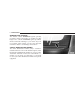
INTRODUCTION WARNINGS AND CAUTIONS This manual contains WARNINGS against operating procedures which could result in an accident or bodily injury. It also contains CAUTIONS against procedures which could result in damage to your vehicle. If you do not read this entire manual you may miss important information. Observe all Warnings and Cautions.
THINGS TO KNOW BEFORE STARTING YOUR VEHICLE 2 CONTENTS m A Word About Your Keys . . . . . . . . . . . . . . . . . 9 ▫ Start Lockout . . . . . . . . . . . . . . . . . . . . . . . . .14 ▫ Keys . . . . . . . . . . . . . . . . . . . . . . . . . . . . . . . 9 m Remote Keyless Entry . . . . . . . . . . . . . . . . . . . .14 ▫ Obtaining Replacement Keys . . . . . . . . . . . . . . 9 ▫ To Unlock The Doors . . . . . . . . . . . . . . . . . . .15 ▫ Ignition Key Removal . . . . . . . . . . . . . . . . . . .
THINGS TO KNOW BEFORE STARTING YOUR VEHICLE m Power Windows . . . . . . . . . . . . . . . . . . . . . . . .21 ▫ Child Restraint . . . . . . . . . . . . . . . . . . . . . . . .47 ▫ Power Window Operation With The Convertible Top Switch (Roadster Only) . . . . . .22 m Engine Break-In Recommendations . . . . . . . . . .55 m Rear Liftgate/Decklid Release . . . . . . . . . . . . . .23 m Occupant Restraints . . . . . . . . . . . . . . . . . . . . .23 ▫ Lap/Shoulder Belts . . . . . . . . . . . . . . . . .
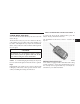
THINGS TO KNOW BEFORE STARTING YOUR VEHICLE A WORD ABOUT YOUR KEYS You can insert the double-sided keys into the locks with either side up. The dealer that sold you your new vehicle has the key code numbers for your vehicle locks. These numbers can be used to order duplicate keys only from an authorized dealer. Ask your dealer for these numbers and keep them in a safe place. 9 To release the key from the folded position, press the button. The key unfolds from the fob.
THINGS TO KNOW BEFORE STARTING YOUR VEHICLE Important! Removing the key from the steering lock activates the start lock-out. The engine cannot be started. Turning the key in the steering lock to the ON/RUN position deactivates the start lock-out. NOTE: In case the engine cannot be started, and START and ERROR are shown in the odometer display field, the system is not operational. Contact an authorized dealer. Ignition Key Removal Turn the key to the LOCK position and remove the key.
THINGS TO KNOW BEFORE STARTING YOUR VEHICLE GLOVE COMPARTMENT LOCK The glove compartment can be locked by turning the key straight up to the vertical or right position, and then removing the key. To unlock the glove compartment, turn the key to the horizontal or left position, and then remove the key.
THINGS TO KNOW BEFORE STARTING YOUR VEHICLE The doors can be unlocked by pulling on the inside door handle, pressing and releasing the top portion of the central locking switch located in the console, or by pressing and releasing the Unlock transmit button on the key fob. Both doors can also be unlocked by turning the key counterclockwise in the driver’s door. NOTE: If the key in the ignition switch is in the ON/RUN position, the vehicle cannot be locked or unlocked with the remote control.
THINGS TO KNOW BEFORE STARTING YOUR VEHICLE was previously locked with the central locking switch, the complete vehicle is unlocked when a door is opened from the inside. NOTE: The fuel filler door and center console (roadster only) cannot be locked or unlocked with the central locking switch. Automatic Central Locking The central locking switch also operates the automatic central locking feature.
THINGS TO KNOW BEFORE STARTING YOUR VEHICLE NOTE: To help prevent the vehicle battery from discharging during short periods of inactivity, perform the following: 1. Make sure that the rear liftgate/decklid, hood and doors are completely closed. 2. Make sure that remote transmitter is operating and that the battery is good. 3. Make sure that the hood, rear liftgate/decklid and door switches are in adjustment. Perform the quick system check which follows: Use the remote transmitter to set the alarm.
THINGS TO KNOW BEFORE STARTING YOUR VEHICLE 15 To Unlock the Doors Press and release the unlock button on the key fob. NOTE: If within 40 seconds of unlocking with the key fob, neither door is opened, the key is not inserted in the ignition switch, or the central locking switch is not activated, the vehicle will automatically lock. Press the Unlock transmit button on the key fob once to unlock driver’s door, rear liftgate/decklid, fuel filler door, and center console (roadster only).
THINGS TO KNOW BEFORE STARTING YOUR VEHICLE To Lock The Doors Press the Lock button on the key fob once. All turn signal lights blink three times to indicate that the vehicle is locked. If the turn signal lights do not blink, a door or rear liftgate/decklid is not closed properly. The entire vehicle, including the fuel filler door, may be locked or unlocked by using the key in the driver’s door.
THINGS TO KNOW BEFORE STARTING YOUR VEHICLE Panic Alarm The panic alarm unlocks the driver’s door, turns on the interior lights, flashes the foglights and sounds the horn for about three minutes or until the alarm is turned off. The vehicle can be driven while in the Panic mode. To Use the Panic Alarm Press and hold the Panic button to activate the alarm. Press and hold the Panic button or unlock the door with the key to deactivate the alarm.
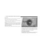
THINGS TO KNOW BEFORE STARTING YOUR VEHICLE Transmitter Battery Service The recommended replacement Lithium battery is Panasonict CR 2025 or equivalent. To change the batteries: • Insert the new batteries in the direction of the arrow with the positive symbol facing upwards. • Replace the battery cover and press on it until you feel it engage. • Press release button (2) on the key fob. The key folds out. • Press the battery cover (1) in the direction of the arrow. • Remove the old batteries.
THINGS TO KNOW BEFORE STARTING YOUR VEHICLE approximately 30 seconds, insert the key in the ignition and turn it to the ON/RUN position. The remote control should once again be operational. SECURITY ALARM SYSTEM The system monitors the doors, rear liftgate/decklid, hood, and ignition for unauthorized operation. The security alarm system is automatically armed or disarmed with the remote control or any of your vehicle’s keys by locking or unlocking the vehicle.
THINGS TO KNOW BEFORE STARTING YOUR VEHICLE The tow-away alarm remains switched off until the vehicle is locked again with the key or the remote control, at which time it is automatically reactivated. DECKLID INTERNAL EMERGENCY RELEASE ROADSTER As a security measure, a Decklid Internal Emergency Release lever is built into the decklid latching mechanism.
THINGS TO KNOW BEFORE STARTING YOUR VEHICLE 21 WARNING! If the battery voltage drops below the minimum threshold at any time, the Trunk Internal Emergency Release will not function. 2 WARNING! The Trunk Internal Emergency Release will not function during the convertible top operation. POWER WINDOWS The power window switches are located in the console. To operate, turn the key in the ignition switch to the ACC or ON/RUN position.
THINGS TO KNOW BEFORE STARTING YOUR VEHICLE For express opening of windows, press the switch past the resistance point and release; the window lowers to the fully open position. To interrupt the procedure, briefly press the switch again and release. When closing the windows, be sure that there is no danger of anyone being harmed by the closing procedure. WARNING! When leaving the vehicle, always remove the key from the ignition switch, and lock the vehicle.
THINGS TO KNOW BEFORE STARTING YOUR VEHICLE REAR LIFTGATE/DECKLID RELEASE You can open the rear liftgate/decklid by using the handle located on the liftgate/decklid just above the rear license plate pocket. WARNING! Do not allow children to have access to the rear cargo area by climbing into the rear cargo area from outside. Always close the liftgate/decklid when your vehicle is unattended. Once in the cargo area, young children may have difficulty leaving the vehicle.
THINGS TO KNOW BEFORE STARTING YOUR VEHICLE Buckle up even though you are an excellent driver, even on short trips. Someone on the road may be a poor driver and cause a collision that includes you. This can happen far away from home or on your street. Research has shown that seat belts save lives. They also can reduce the seriousness of injuries in a collision. Some of the worst injuries happen when people are thrown from the vehicle.
THINGS TO KNOW BEFORE STARTING YOUR VEHICLE WARNING! • Wearing a seat belt incorrectly is dangerous. Seat belts are designed to go around the large bones of your body. These are the strongest parts of your body and can take the forces of a collision the best. Wearing your belt in the wrong place could make your injuries in a collision much worse. You might suffer internal injuries, or you could even slide out of part of the belt.
THINGS TO KNOW BEFORE STARTING YOUR VEHICLE 2. The seat belt latch plate is above the back of your seat. Grasp the latch plate and pull out the belt. Slide the latch plate up the webbing as far as necessary to make the belt go around your lap. 3. When the belt is long enough to fit, insert the latch plate into the buckle until you hear a “click.” 4. Position the lap belt across your thighs, below your abdomen. To remove slack in the lap belt portion, pull up a little on the shoulder belt, as shown.
THINGS TO KNOW BEFORE STARTING YOUR VEHICLE 5. To loosen the lap belt if it is too tight, tilt the latch plate away from you and pull on the lap belt. Remember that a snug belt reduces the risk of sliding under the belt in a collision. 6. Position the shoulder belt on your chest so that it is comfortable and not resting on your neck. The retractor will withdraw any slack in the belt. 7. To release the belt, push the red button on the buckle. The belt will automatically retract to its stowed position.
THINGS TO KNOW BEFORE STARTING YOUR VEHICLE WARNING! WARNING! • A lap belt worn too high can increase the risk of internal injury in a collision. The belt forces won’t be at the strong hip and pelvic bones, but across your abdomen. Always wear the lap belt as low as possible and keep it snug. Seat belt systems must always be replaced after an impact severe enough to fire the emergency locking retractors.
THINGS TO KNOW BEFORE STARTING YOUR VEHICLE Seat Belts and Pregnant Women We recommend that pregnant women use the seat belts throughout their pregnancy. Keeping the mother safe is the best way to keep the baby safe. Pregnant women should wear the lap part of the belt across the thighs and as snug across the hips as possible. Keep the belt low so that it does not come across the abdomen. That way the strong bones of the hips will take the force if there is a collision.
THINGS TO KNOW BEFORE STARTING YOUR VEHICLE Supplemental Restraint System (SRS) - Airbag This vehicle has airbags for the driver and passenger as a supplement to the seat belt restraint systems. The driver’s airbag is mounted in the steering wheel. The passenger frontal airbag is mounted in the instrument panel, under a cover marked SRS/AIRBAG. These airbags inflate in higher speed frontal impacts.
THINGS TO KNOW BEFORE STARTING YOUR VEHICLE WARNING! • Do not put anything on or around the front airbag covers or attempt to manually open them. You may damage the airbags and you could be injured because the airbags are not there to protect you. These protective covers are designed to open only when the airbags are inflated. • Do not place objects between you and the side airbags; the performance could be adversely affected and/or objects could be pushed into you, causing serious injury.
THINGS TO KNOW BEFORE STARTING YOUR VEHICLE Children that are not big enough to properly wear the vehicle seat belt (see section on “Child Restraint”) should be secured in child safety seats or booster seats that are appropriate for the child’s age, height, and weight. Older children who do not use child safety seats or booster seats should ride properly buckled. Never allow children to place the shoulder belt behind them or under the arm.
THINGS TO KNOW BEFORE STARTING YOUR VEHICLE 33 WARNING! WARNING! After installing a child safety seat or booster seat on the passenger seat, do not adjust the back rest forward. This could cause a higher load being perceived by the OCS system which in turn could lead to the passenger airbag being turned on. Failure to follow this warning could result in serious or fatal injury.
THINGS TO KNOW BEFORE STARTING YOUR VEHICLE Airbag System Components The airbag system consists of the following: • Occupant Restraint Controller • Airbag Warning Light • Driver and passenger frontal airbag/inflator units • Driver and passenger side airbag/inflator units • Driver and Passenger Inflatable Knee Blocker • Driver and Front Passenger Seat Belt Pretensioners • Side impact sensors • Front Passenger Seat Occupant Classification System (OCS) How the Front Airbag System Works • The Occupant Rest
THINGS TO KNOW BEFORE STARTING YOUR VEHICLE WARNING! Ignoring the AIRBAG light in your instrument panel could mean you won’t have the airbags to protect you in a collision. If the light does not come on, stays on after you start the vehicle, or if it comes on as you drive, have the airbag system checked right away. WARNING! Do not put anything on or around the airbag covers or attempt to manually open them.
THINGS TO KNOW BEFORE STARTING YOUR VEHICLE • The Knee Blocker Airbag helps protect the knees and working with the seatbelts, position you for the best interaction with the airbags. If a Deployment Occurs WARNING! Deployed airbags can’t protect you in another collision. Have the airbags replaced by an authorized dealer as soon as possible.
THINGS TO KNOW BEFORE STARTING YOUR VEHICLE If you do have a collision which deploys the airbags, any or all of the following may occur: • The nylon airbag material may sometimes cause abrasions and/or skin reddening to the driver and passenger as the airbags deploy and unfold. The abrasions are similar to friction rope burns or those you might get sliding along a carpet or gymnasium floor. They are not caused by contact with chemicals. They are not permanent and normally heal quickly.
THINGS TO KNOW BEFORE STARTING YOUR VEHICLE • When a side impact above a predetermined threshold occurs, the sensors signal the inflator on the impacted side of the vehicle. A large quantity of nontoxic nitrogen gas is generated to inflate the airbag. The door panel opens to allow the airbag to inflate to its full size. WARNING! • Do not put anything on or around the airbag covers or attempt to manually open them.
THINGS TO KNOW BEFORE STARTING YOUR VEHICLE • The operational readiness of the side airbag system is verified by the airbag indicator light in the instrument cluster when turning the key in the ignition switch to the ON/RUN position. If no fault is detected, the light will go out after approximately four seconds. After the light goes out, the system continues to monitor the components and circuitry of the airbag system and will indicate a malfunction by coming on again.
THINGS TO KNOW BEFORE STARTING YOUR VEHICLE How the Occupant Classification System (OCS) System Works The Occupant Classification System (OCS) will classify an occupant in the front passenger seat into a size category based on sensor readings from within the seat cushion. Occupants should try to remain in a normally seated position. If the occupant’s weight is transferred to another object in the vehicle (i.e. feet on the dashboard), the OCS may not be able to properly approximate occupant size.
THINGS TO KNOW BEFORE STARTING YOUR VEHICLE will not inflate. For most children properly seated on the front seat and most properly installed child restraint systems, the airbag will be disabled and the PAD indicator light will be on. However, under certain conditions even with the child restraint system has been installed properly, the PAD indicator light may not be on even though the air bag is disabled.
THINGS TO KNOW BEFORE STARTING YOUR VEHICLE How the Occupant Classification Module (OCM) Works The Occupant Classification Module (OCM) is located beneath the passenger seat.. The OCM classifies the occupant into one of three size categories based on the input from the Bladder Assembly and a Belt Tension Sensor. The size categories include empty, child, and adult. The OCM sends the Occupant Classification to the ORC to determine if a front passenger airbag is allowed.
THINGS TO KNOW BEFORE STARTING YOUR VEHICLE How the Driver/Passenger Inflatable Knee Blockers Works When the ORC and the impact sensors detect a collision requiring the Driver/Passenger Inflatable Knee Blockers, it signals the inflator unit. A quantity of nontoxic gas is generated to inflate the Driver/Passenger Inflatable Knee Blockers.
THINGS TO KNOW BEFORE STARTING YOUR VEHICLE If the airbag is turned off when there is any other occupant at that position, the supplemental restraint provided by the airbag will not be available. To turn OFF the passenger front airbag, use the on/off switch located on the instrument panel. NOTE: When the passenger airbag is turned off, the yellow airbag off light will illuminate.
THINGS TO KNOW BEFORE STARTING YOUR VEHICLE 45 To Shut Off the Passenger Airbag: To Turn On the Passenger Airbag: • Place the ignition key in the on/off switch, turn the key clockwise, and remove the key from the switch. This will shut off the passenger front airbag. • Place the ignition key in the on/off switch, turn the key counterclockwise, and remove the key from the switch. This will turn on the passenger airbag.
THINGS TO KNOW BEFORE STARTING YOUR VEHICLE Maintaining Your Airbag System WARNING! • Unapproved modifications or service procedures to the front passenger seat assembly, its related components, or seat cover may inadvertently change the airbag deployment in case of a frontal crash. This could result in death or serious injury to the front seat passenger if the vehicle is involved in an accident. A modified vehicle may not comply with required Federal Motor Vehicle Safety Standards (FMVSS).
THINGS TO KNOW BEFORE STARTING YOUR VEHICLE 47 Airbag Light You will want to have the airbags ready for your protection in case of a collision. While the airbag Supplemental Restraint System (SRS) is designed to be maintenance free, if any of the following occurs, have an authorized dealer service the system immediately. Child Restraint Everyone in your vehicle needs to be buckled up all the time, babies and children, too.
THINGS TO KNOW BEFORE STARTING YOUR VEHICLE Infants and Child Restraints There are different sizes and types of restraints for children from newborn size to the child almost large enough for an adult safety belt. Always check the child seat Owner’s Manual to ensure you have the right seat for your child. Use the restraint that is correct for your child: • Safety experts recommend that children ride rearward-facing in the vehicle until they are at least one year old and weigh at least 9 kg (20 lbs.).
THINGS TO KNOW BEFORE STARTING YOUR VEHICLE 49 Here are some tips on getting the most out of your child restraint: NOTE: For additional information refer www.seatcheck.org or call 1–866–SEATCHECK. • Before buying any restraint system, make sure that it has a label certifying that it meets all applicable Safety Standards. We also recommend that you make sure that you can install the child restraint in the vehicle where you will use it before you buy it.
THINGS TO KNOW BEFORE STARTING YOUR VEHICLE Children Too Large For Booster Seats Children who are large enough to wear the shoulder belt comfortably, and whose legs are long enough to bend over the front of the seat when their back is against the seat back, should use the lap/shoulder belt. • Make sure that the child is upright in the seat. • The lap portion should be low on the hips and as snug as possible. • Check belt fit periodically.
THINGS TO KNOW BEFORE STARTING YOUR VEHICLE 51 The passenger seat lower anchorages are round bars, located at the rear of the seat cushion where it meets the seat back, and are just visible when you lean in to install the child restraint. You will easily feel them if you run your finger along the intersection of the seat back and seat cushion surfaces. The passenger seat tether anchorage is located on the back of the seat cushion frame. It is visible by moving the passenger seat forward in the vehicle.
THINGS TO KNOW BEFORE STARTING YOUR VEHICLE You will first loosen the adjusters on the lower straps and on the tether strap so that you can more easily attach the hooks or connectors to the vehicle anchorages. Next, you can attach the tether strap to the anchor by moving the passenger seat forward. Route the child restraint tether directly over the top of the seat, through the strap near the top of the seat back, and attach the hook to the anchor bar.
THINGS TO KNOW BEFORE STARTING YOUR VEHICLE WARNING! Improper installation of a child restraint to the LATCH anchorages can lead to failure of an infant or child restraint. The child could be badly injured or killed. Follow the manufacturer’s directions exactly when installing an infant or child restraint. Installing Child Restraints Using the Vehicle Seat Belt Child restraints can be securely fastened in the passenger seat using the seat belts.
THINGS TO KNOW BEFORE STARTING YOUR VEHICLE To attach the tether strap to the anchor, move the seatback fully forward. Pass the child restraint tether hook over the top of the seat, through the strap near the top of the seat back, and attach it to the anchor bar behind the passenger seat, below the seatback. After securing the tether hook to the bar, recline the seatback fully rearward and move the seat to its most rearward position.
THINGS TO KNOW BEFORE STARTING YOUR VEHICLE ENGINE BREAK-IN RECOMMENDATIONS The engine in your new Crossfire does not require a long break-in period. Following these few simple guidelines is all that is necessary for a good break-in. • Drive your vehicle at moderate vehicle and engine speeds during the first 1,000 miles (1,600 km). • Do not make any full throttle starts and avoid full throttle acceleration. • Use the proper transmission gear for your speed range. • Avoid excessive idling.
THINGS TO KNOW BEFORE STARTING YOUR VEHICLE • To avoid drawing exhaust gases into the vehicle, close the rear liftgate/decklid while driving. However, if for some reason it must remain open, close all windows. Adjust the heating or cooling system to force outside air into the vehicle. Set the blower at high speed. Safety Checks You Should Make Inside the Vehicle Seat Belts Inspect the belt system periodically, checking for cuts, frays and loose parts. Damaged parts must be replaced immediately.
THINGS TO KNOW BEFORE STARTING YOUR VEHICLE Fluid Leaks Check area under vehicle after overnight parking for fuel, water, oil, or other fluid leaks. Also, if gasoline fumes are present, the cause should be corrected immediately. 57 NOTE: Use of the air conditioning may cause puddles of water to form under the vehicle.
UNDERSTANDING THE FEATURES OF YOUR VEHICLE CONTENTS 3 m Convertible Top Operation . . . . . . . . . . . . . . . .62 m Mirrors . . . . . . . . . . . . . . . . . . . . . . . . . . . . . .77 ▫ To Lower The Top . . . . . . . . . . . . . . . . . . . . . .63 ▫ Inside Day/Night Mirror . . . . . . . . . . . . . . . . .77 ▫ To Raise The Top . . . . . . . . . . . . . . . . . . . . . .67 ▫ Exterior Mirrors Folding Feature . . . . . . . . . . .77 ▫ Convertible Top Lamp And Audible Signal Chart . . . . . . . . .
UNDERSTANDING THE FEATURES OF YOUR VEHICLE ▫ Heated Seats (If Equipped) . . . . . . . . . . . . . . .83 ▫ Windshield Wipers And Washer . . . . . . . . . . . .90 m To Open And Close The Hood . . . . . . . . . . . . .84 ▫ Mist Function . . . . . . . . . . . . . . . . . . . . . . . . .91 m Interior Lights . . . . . . . . . . . . . . . . . . . . . . . . .85 m Telescoping Steering Column . . . . . . . . . . . . . .92 ▫ Front Map/Reading Lights . . . . . . . . . . . . . . .
UNDERSTANDING THE FEATURES OF YOUR VEHICLE 61 ▫ Using The Universal Transceiver . . . . . . . . . . 109 ▫ Security . . . . . . . . . . . . . . . . . . . . . . . . . . . . 109 ▫ Erasing Universal Transceiver Buttons . . . . . . . 109 m Umbrella Hook . . . . . . . . . . . . . . . . . . . . . . . 110 ▫ Reprogramming a Single Button . . . . . . . . . . .
UNDERSTANDING THE FEATURES OF YOUR VEHICLE CONVERTIBLE TOP OPERATION WARNING! The convertible top does not provide the structural protection that a reinforced metal roof does and the fabric top cannot be expected to prevent the ejection of the occupants of a vehicle in a collision. Therefore, it is important that all occupants wear their seat belts at all times when riding in a convertible.
UNDERSTANDING THE FEATURES OF YOUR VEHICLE CAUTION! When opening and closing the convertible top, make sure that: • There is sufficient clearance of at least 6 ft. (1.8m) for the convertible top to move up. • Nothing is placed on the tonneau cover. • The outside temperature is above 32°F (0°C). Otherwise the convertible top and other parts of the vehicle could be damaged. CAUTION! Use caution when putting items into the storage compartment with the top in the closed position.
UNDERSTANDING THE FEATURES OF YOUR VEHICLE CAUTION! CAUTION! To avoid possible damage to the tonneau cover and convertible top, do not allow the convertible top to remain in the suspended position. After approximately 10 minutes in the suspended position, the hydraulic pressure will be released which will allow the top and the tonneau cover to lower. The convertible top switch can be pressed to cancel this operation.
UNDERSTANDING THE FEATURES OF YOUR VEHICLE NOTE: See label attached to underside of decklid. 65 2. Make sure the decklid is closed. CAUTION! Be sure to turn the ignition to the “ON/RUN” position before releasing the top from the windshield header. The windows will not go down if the top is released from the header without the ignition turned “ON”. The side windows can be damaged if the doors are opened or closed with the windows up and the top released from the windshield header. 3.
UNDERSTANDING THE FEATURES OF YOUR VEHICLE NOTE: Once the release handle is rotated, the windows will automatically go down. 5. Push up on the convertible top latch handle to create a gap between the header and top of approximately 8 inches (200 mm). As soon as the top is free, rotate the latch handle counterclockwise just over one quarter turn and push it up into the stored position.
UNDERSTANDING THE FEATURES OF YOUR VEHICLE NOTE: Once the top is lowered and the audible signal is heard, you can continue to push the convertible top switch down or push it within 2 seconds to raise the windows. The windows can also be closed/opened later using the power window switches. 67 CAUTION! To prevent mildew, the convertible top must be dry before lowering it into the storage compartment. Do not lower a frozen convertible top until thawed and dry.
UNDERSTANDING THE FEATURES OF YOUR VEHICLE 3. Turn the ignition key to the ON/RUN position and press down on the front of the convertible top switch. NOTE: If the top is latched to the windshield header before the rear of the top is properly latched, an audible warning will sound and the top raising operation will stop. 5. Pull the latch handle down from the storage position and turn it clockwise just over one quarter turn. 6.
UNDERSTANDING THE FEATURES OF YOUR VEHICLE 7. When the top engages to the header, turn the latch handle counterclockwise just over one quarter turn to the lock position and push the latch handle up to the stored position. The top is now secured in the closed position. NOTE: The convertible top switch indicator will light up and an audible warning will be heard if you start driving the vehicle without the top fully locked in the closed position.
UNDERSTANDING THE FEATURES OF YOUR VEHICLE CAUTION! Once the cargo compartment divider is folded forward to increase the cargo compartment capacity, the tonneau cover flaps are exposed and can be damaged by long items being put into the cargo compartment.
UNDERSTANDING THE FEATURES OF YOUR VEHICLE Convertible Top Lamp and Audible Signal Chart Below is a table containing all of the visual and audible signals that can be seen or heard during top operation or if a fault is present.
UNDERSTANDING THE FEATURES OF YOUR VEHICLE CONSOLE FEATURES The console has a power outlet/cigar lighter, an ash tray with a coin holder, a cupholder (if equipped), and the passenger airbag light. In addition, there are switches to control the heated seats (if equipped), rear spoiler, electronic stability program (ESP), hazard flashers, central locking, rear defroster and towing alarm.
UNDERSTANDING THE FEATURES OF YOUR VEHICLE 73 Storage Compartments (If Equipped) There is a storage compartment in the console. To open the storage compartment, lift the lid with the finger depressions on either side. To close, lower the lid until the lock engages. 3 Additionally, storage pockets are located on the wall behind each seat and on each door panel. A storage pouch is located on the rear wall between the seats, and the driver’s sunvisor has a document strap.
UNDERSTANDING THE FEATURES OF YOUR VEHICLE Ashtray Lightly touch the bottom of the ashtray cover. The ashtray will open automatically. To remove the ashtray insert, pull the ashtray past the detent. Hold both sides of the insert, and pull up. To install the ashtray, place it in the frame and push down to engage. WARNING! Remove the ashtray only with the vehicle stopped and the ignition off. Otherwise, the vehicle might move unexpectedly as a result of unintended contact with the gear selector lever.
UNDERSTANDING THE FEATURES OF YOUR VEHICLE Coin Holder With the ashtray open, folding down the cover plate reveals the coin holder, which can accommodate nine coins in various sizes up to a U.S. quarter. The coin slots are shaped to retain the coins, and the cover plate ensures that the coins remain in the coin holder. Power Outlet/Cigar Lighter The dual-purpose power outlet is located in the console, next to the passenger airbag off warning light.
UNDERSTANDING THE FEATURES OF YOUR VEHICLE Glove Compartment To lock the glove compartment, turn the key to the right and remove. To unlock, turn the key to the left and remove. Pull on the handle to open the glove compartment. CUPHOLDER (If Equipped) The cupholder is located in the console. To open the cupholder, gently press downward on the front edge of the top panel, and then release. The cupholder will open automatically.
UNDERSTANDING THE FEATURES OF YOUR VEHICLE MIRRORS Inside Day/Night Mirror Adjust the mirror to center on the view through the rear window. A two point pivot system allows for horizontal and vertical mirror adjustment. 77 Exterior Mirrors Folding Feature All exterior mirrors are hinged to move forward or rearward to resist damage. The hinges have three detent positions: full forward, full rearward, and normal.
UNDERSTANDING THE FEATURES OF YOUR VEHICLE Power Remote Control Outside Mirrors The mirrors can be adjusted by using the remote control located in the console. Rotate the switch to the right to select the right mirror, rotate to the left to select the left mirror. Then use the switch to adjust the selected mirror to the desired direction.
UNDERSTANDING THE FEATURES OF YOUR VEHICLE Vanity Mirrors 79 SEATS Your vehicle’s seats can be adjusted either manually or electrically, depending on how your vehicle is equipped. WARNING! • Adjusting a seat while the vehicle is moving is dangerous. The sudden movement of the seat could cause you to lose control. The seat belt might not be properly adjusted and you could be injured. Adjust the seat only while the vehicle is parked. A vanity mirror is on each sun visor.
UNDERSTANDING THE FEATURES OF YOUR VEHICLE NOTE: When moving the seat, be sure that there are no items in the footwell or behind the seats. Otherwise you could damage the seats. Manual Seat Adjustments (If Equipped) Seat Height (Drivers Seat Only) • Pull up on handle 3. • To lower the seat, use your body weight to push the seat downward. • To raise the seat, lift your body weight off the seat to obtain a higher seat position. • Release handle 3 when you are at your desired seat level.
UNDERSTANDING THE FEATURES OF YOUR VEHICLE Backrest Tilt • Turn handwheel 2 forward or backward to adjust the backrest tilt to your desired position which allows your arms to slightly bend when holding the steering wheel. Head Restraint Height WARNING! For your protection, drive only with properly positioned head restraints. Adjust head restraint to support the back of the head approximately at ear level. Do not drive the vehicle without the seat head restraints.
UNDERSTANDING THE FEATURES OF YOUR VEHICLE Driver Eight-Way Power Seat (If Equipped) The switches to adjust the power seats are located on the outboard side of each seat. The driver’s seat features eight-way power adjustment - horizontal, vertical, cushion tilt and back angle.
UNDERSTANDING THE FEATURES OF YOUR VEHICLE 83 Passenger Four-Way Power Seat (If Equipped) The switches to adjust the passenger seat are also on the outboard side of the seat. The passenger seat provides four-way adjustment - horizontal and back angle. 3 After turning the ignition switch ON, you can choose the HI, LO, or OFF setting. Indicators on the switches show which setting has been selected. Heated Seats (If Equipped) This feature heats the driver and passenger seats.
UNDERSTANDING THE FEATURES OF YOUR VEHICLE TO OPEN AND CLOSE THE HOOD To open the hood, pull the release lever located inside your vehicle, below the instrument panel. WARNING! Then, reach under the hood and pull upward on the safety latch and lift the hood. To prevent possible damage, close the hood by dropping it from approximately 12 inches (30 cm). If the hood is not fully latched, it could fly up when the vehicle is moving, and block your forward vision. You could have a collision.
UNDERSTANDING THE FEATURES OF YOUR VEHICLE INTERIOR LIGHTS A two-position mode selector switch controls the interior lights located in the overhead console. 85 Front Map/Reading Lights These lights are located between the sun visors. A single centrally located switch operates both lights. 3 The AUTO mode turns the lights on when a door is open or ajar, or when locking or unlocking the vehicle. AUTO mode also has a “fade to off” feature. When the doors are closed or locked, they gradually “fade” off.
UNDERSTANDING THE FEATURES OF YOUR VEHICLE Instrument Panel Lighting With the parking lights or headlights on, rotate the dimmer control to the left of the speedometer to increase or decrease brightness of the instrument panel. Night Security Illumination For added security when exiting the vehicle after driving with the exterior lights on, the lights will switch on again for approximately 30 seconds after closing the last door. The lights-on timing can be changed at your authorized dealer.
UNDERSTANDING THE FEATURES OF YOUR VEHICLE Lights-On Reminder If the headlights or parking lights are left on after the ignition is turned off, a warning will sound if the driver’s door is opened. Daytime Running Lights (Where Applicable) VEHICLES WITH AUTOMATIC TRANSMISSION The low beam headlights, parking lights, side marker lights, taillights and license plate lights are automatically switched on whenever the vehicle is started and the transmission gear selector is in a driving position.
UNDERSTANDING THE FEATURES OF YOUR VEHICLE CAUTION! Standing lamps are intended for short term use when parking. If these lights are left on for a long period of time, your car’s battery may drain, causing a possible starting problem. Assure that the headlamp switch is in the OFF position when leaving the vehicle. MULTIFUNCTION CONTROL LEVER Turn Signals Move the multifunction control lever up to activate the right turn signal; move the lever down to activate the left turn signal.
UNDERSTANDING THE FEATURES OF YOUR VEHICLE 89 Headlight Dimmer Switch Push the multifunction control lever toward the instrument panel to turn the headlights to high beam. Pull the lever toward you to switch to low beam.
UNDERSTANDING THE FEATURES OF YOUR VEHICLE Passing Light You can signal another vehicle with your headlights by lightly pulling the multifunction control lever toward the steering wheel. This will cause the headlights to turn on at high beam and remain on until the control lever is released. Windshield Wipers And Washer The wipers and washer are operated by a switch in the multifunction control lever. Turn the end of the lever to select desired wiper speed: off, intermittent, normal, or fast.
UNDERSTANDING THE FEATURES OF YOUR VEHICLE 91 Push the end of the lever inward and hold it to activate the wiper and washer together. 3 WARNING! Mist Function Push the end of the multifunction control lever inward briefly for a single wipe without adding washer fluid. Use this feature only when the windshield is wet. Sudden loss of visibility through the windshield could lead to an accident. You might not see other vehicles or other obstacles.
UNDERSTANDING THE FEATURES OF YOUR VEHICLE TELESCOPING STEERING COLUMN Unlock the steering column by pulling out the handle located directly below the column. The indicator light located in the instrument cluster will come on. To lengthen or shorten the steering column, pull out or push in the steering wheel. Lock the steering column in position by pushing the handle in until it engages. The indicator light in the instrument cluster will go out. WARNING! Do not adjust the steering wheel while driving.
UNDERSTANDING THE FEATURES OF YOUR VEHICLE 93 more of your tires is significantly under—inflated. Accordingly, when the low tire pressure telltale illuminates, you should stop and check your tires as soon as possible, and inflate them to the proper pressure, Driving on a significantly under-inflated tire causes the tire to overheat and can lead to tire failure. Under-inflation also reduced fuel efficiency and tire tread life, and may affect the vehicle’s handling and stopping ability.
UNDERSTANDING THE FEATURES OF YOUR VEHICLE The TPM system will cause the indicator lamp in the instrument cluster to illuminate whenever the pressure in one tire falls 25% below the recommended pressure shown on the vehicle’s tire label. NOTE: The pressure in your tires changes with temperature. A significant decrease in temperature could reduce cold inflation pressure below the TPM setpoint.
UNDERSTANDING THE FEATURES OF YOUR VEHICLE 95 NOTE: The standard TIREFIT system (refer to What To Do In Emergencies for more information) is specifically designed to operate in conjunction with the TPM system, and will not damage the sensors. If your tire pressure is low, you should correct your tire inflation pressure as soon as possible and inspect all of your tires. Low tire pressure will cause the tire pressure light to illuminate.
UNDERSTANDING THE FEATURES OF YOUR VEHICLE 2. This device must accept any interference that may be received, including interference that may cause undesired operation. NOTE: Changes and modifications not expressly approved by the party responsible for compliance could void the user’s authority to operate the equipment. REAR SPOILER CAUTION! Do not push or pull on the spoiler when deployed. Damage to the spoiler could result. A rear spoiler enhances vehicle stability.
UNDERSTANDING THE FEATURES OF YOUR VEHICLE The spoiler control also incorporates an emergency stop feature. If, for any reason, spoiler motion needs to be stopped, pressing either the top or bottom of the switch will stop the spoiler motion. Once the deployment speed is reached, however, the spoiler deploys to its full up position. The spoiler will deploy as a safety precaution if the ESP system detects a large difference in wheel speed between the front and rear wheels.
UNDERSTANDING THE FEATURES OF YOUR VEHICLE WARNING! Do not drive the vehicle at speeds above 62 mph (100 km/h) if the red spoiler warning indicator is illuminated. You could have reduced vehicle stability and control. WARNING! Keep hands and fingers away from the spoiler and spoiler linkage when the spoiler is deploying or retracting. The linkage could pinch your fingers and cause serious injury.
UNDERSTANDING THE FEATURES OF YOUR VEHICLE 99 BAS complements the antilock brake system (ABS). Applying the brakes very quickly results in maximum BAS assistance. To receive the benefit of the system, you must apply continuous full braking power during the stopping sequence. Do not reduce brake pedal pressure. turned to the ON/RUN position. They should go out with the engine running.
UNDERSTANDING THE FEATURES OF YOUR VEHICLE The ESP enhances directional control and reduces driving wheel spin of the vehicle under various driving conditions. The ESP system corrects for over/understeering of the vehicle by applying brakes to the appropriate wheel. Engine torque is also limited. The ESP warning light, located in the instrument cluster, starts to flash as soon as the tires lose traction and the wheels begin to spin.
UNDERSTANDING THE FEATURES OF YOUR VEHICLE wheel regains sufficient traction. The traction control engages at approximately 24 mph (40 km/h), and switches off at 50 mph (80 km/h). If the ESP warning light begins to flash during acceleration, ease up on the accelerator and apply as little throttle as possible. Be sure to adapt your speed and driving to the prevailing road conditions. When the ESP warning light is illuminated continuously, the ESP is switched off.
UNDERSTANDING THE FEATURES OF YOUR VEHICLE ELECTRONIC SPEED CONTROL The electronic speed control automatically maintains the set speed by actively regulating the throttle setting. Any speed above approximately 20 mph (30 km/h) can be maintained with the electronic speed control by operating the lever. To accelerate and set a speed, lift the lever up. Lift and hold the lever to accelerate, or lift and release to set a speed. To decelerate and set a speed, press the lever down.
UNDERSTANDING THE FEATURES OF YOUR VEHICLE 103 To Vary The Speed Setting If a set speed needs to be adjusted slightly, lift up or hold down the speed control lever briefly until the desired speed is reached. A single tap on the lever up or down will change the speed in 0.6 mph (1 km/h) increments. When the lever is released, the newly set speed remains. To increase the speed for passing, use the accelerator. After the accelerator is released, the previously set speed will resume automatically.
UNDERSTANDING THE FEATURES OF YOUR VEHICLE To Deactivate A soft tap on the brake pedal, or normal brake pressure while slowing the vehicle, will deactivate the speed control without erasing the memory. Pushing the speed control lever forward or turning the key in the ignition switch to the OFF/LOCK position will turn off the speed control and erase the memory. To Resume Speed To resume a previously set speed, pull the speed control lever toward you, and then release.
UNDERSTANDING THE FEATURES OF YOUR VEHICLE Using Speed Control On Hills Your vehicle is equipped with interactive speed control. This feature activates when driving up or down hills with the speed control engaged and the driver’s foot off the accelerator. WARNING! Speed control can be dangerous where the system can’t maintain a constant speed. Your vehicle could go too fast for the conditions, and you could lose control. An accident could be the result.
UNDERSTANDING THE FEATURES OF YOUR VEHICLE WARNING! WARNING! A moving garage door can cause injury to people and pets in the path of the door. People or pets could be seriously or fatally injured. Only use this transceiver with a garage door opener that has a “stop and reverse” feature, as required by federal safety standards. This includes most garage door opener models manufactured after 1982. Do not use a garage door opener without these safety features, as it could cause injury or death.
UNDERSTANDING THE FEATURES OF YOUR VEHICLE 3. Erase the factory test codes by pressing the two outside buttons. Release the buttons when the light in the overhead console display begins to flash (about 20 seconds). NOTE: Step 3 does not have to be followed to program additional hand-held transmitters. 4. Choose one of the three buttons to program. Place the hand-held controller 1–3 inches (25–76 mm) from the universal transceiver while keeping its indicator light in view. 107 5.
UNDERSTANDING THE FEATURES OF YOUR VEHICLE If the indicator light blinks rapidly for two seconds and then turns to a constant light, continue with Programming Steps 8-10 to complete programming of a rolling code equipped device (most commonly a garage door opener). 8. At the garage door opener receiver (motor-head unit) in the garage, locate the “learn” or “smart” button. This can usually be found where the hanging antenna wire is attached to the motor-head unit. 9.
UNDERSTANDING THE FEATURES OF YOUR VEHICLE 5. Continue to press and hold the universal transceiver button while you press and release every two seconds (“cycle”) your hand-held transmitter until the frequency signal has successfully been accepted by the universal transmitter. (The indicator light will flash slowly and then rapidly.) Proceed with Programming Step 6 to complete. Using the Universal Transceiver To operate the universal transceiver, simply press and release the programmed button.
UNDERSTANDING THE FEATURES OF YOUR VEHICLE This device complies with part 15 of FCC rules and with RS-210 of Industry Canada. Operation is subject to the following conditions: 1. This device may not cause harmful interference. 2. This device must accept any interference that may be received, including interference that may cause undesired operation. NOTE: Changes or modifications not expressly approved by the party responsible for compliance could void the user’s authority to operate the equipment.
UNDERSTANDING YOUR INSTRUMENT PANEL CONTENTS m Instruments And Controls . . . . . . . . . . . . . . . . 112 ▫ Driver – L/R . . . . . . . . . . . . . . . . . . . . . . . . 133 m Instrument Cluster . . . . . . . . . . . . . . . . . . . . . 113 ▫ Telephone Mute Characteristics . . . . . . . . . . . 133 m Instrument Cluster Description . . . . . . . . . . . . 114 m Compact Disc Maintenance . . . . . . . . . . . . . . .
UNDERSTANDING YOUR INSTRUMENT PANEL INSTRUMENTS AND CONTROLS
UNDERSTANDING YOUR INSTRUMENT PANEL INSTRUMENT CLUSTER The instrument cluster displays are activated by either opening the door, pressing the left button within the 113 cluster, or turning the key in the ignition switch to the ON/RUN position.
UNDERSTANDING YOUR INSTRUMENT PANEL INSTRUMENT CLUSTER DESCRIPTION 1. Low Windshield Washer System Fluid Level Warning Light With the key in the ignition switch turned to the ON/RUN position, the indicator light comes on. It should go out when the engine is running. If the indicator light does not go out after starting the engine, or if it comes on while driving, the fluid reservoir is less than 1⁄4 filled.
UNDERSTANDING YOUR INSTRUMENT PANEL CAUTION! The TPMS is designed to monitor your tire pressure and will not function as a tire pressure gauge. After adjusting the air pressure in a tire, there will be a delay before the system updated the display 115 level in the reservoir or the coolant temperature is too high (see the Temperature gauge section). To check the coolant level, the vehicle must be parked on level ground and the engine stopped. Check coolant level only when the coolant is cold.
UNDERSTANDING YOUR INSTRUMENT PANEL If the pointer rises to the red (Hot) area, stop the vehicle and turn off the engine until the problem is corrected. down. The switch is automatically canceled when the steering wheel is turned to a large enough degree. CAUTION! The arrows in the instrument cluster will flash in unison with the respective exterior turn signal. Continuing to drive with an overheated engine cooling system can cause damage to the engine or other components. 5.
UNDERSTANDING YOUR INSTRUMENT PANEL The red markings on the tachometer indicate excessive engine speed. Ease off on the accelerator before reaching the red area. 10. Brake System Warning Light The dual brake system provides a reserve braking capability if a failure occurs in a portion of the hydraulic system. This light monitors both the brake fluid level and the parking brake.
UNDERSTANDING YOUR INSTRUMENT PANEL The indicator light will come on when the exterior light fails. If a brake light fails, the light outage indicator will come on when applying the brake and stays on until the engine is turned off. NOTE: If additional lighting equipment is installed (e.g., auxiliary headlights, etc.) be certain to connect into the fuse before the failure indicator monitoring unit in order to avoid damaging the system. 12.
UNDERSTANDING YOUR INSTRUMENT PANEL The seat belt indicator light will remain lit until the seat belts are fastened. 15. Charging System Indicator Light Should the charging system indicator light fail to come on prior to starting when the key is in the ignition switch in the ON/RUN position, or should it fail to go out after starting or during operation, it indicates a malfunction that must be repaired immediately at an authorized dealer.
UNDERSTANDING YOUR INSTRUMENT PANEL The display can be adjusted with the knob/button located to the left of the clock. • Press the button twice (with the key removed or in the OFF/LOCK or ACC position). 18. Gear Indicator For automatic transmission vehicles, the current gear shift selector range is indicated in the gear range indicator display. 21. Main Odometer, Flexible Service System (FSS) This shows the total distance the vehicle has been driven. 19.
UNDERSTANDING YOUR INSTRUMENT PANEL To reset the trip odometer, press the knob/button once with the key in the ON/RUN position. Press the knob/ button twice with the key removed or in the OFF/LOCK or ACC position. The FSS permits a flexible service schedule that is directly related to the operating conditions of the vehicle. There are two symbols which will appear in the main odometer display field prior to the next suggested service. This symbol represents Service A.
UNDERSTANDING YOUR INSTRUMENT PANEL or while driving when reaching the service warning threshold. It can be canceled manually by pressing the knob/button. starts combined with short distance driving in which the engine does not reach normal operating temperature, reduce the interval between services.
UNDERSTANDING YOUR INSTRUMENT PANEL WARNING! The outside temperature indicator is not designed to serve as an ice-warning device and is unsuitable for that purpose. Indicated temperatures just above the freezing point do not guarantee that the road surface is free of ice. 24. Airbag Light The operational readiness of the airbag system is verified by the airbag indicator light in the instrument cluster when turning the key in the ignition switch to the ACC or ON/RUN position.
UNDERSTANDING YOUR INSTRUMENT PANEL WARNING! Do not drive the vehicle until you have properly locked the steering column. 26. Check Engine Light This light is part of an onboard diagnostic system that monitors the emissions and engine control systems. If a problem is detected in one of these systems, the Check Engine light will come on. The light comes on and stays on briefly as a bulb check when the ignition is first turned on.
UNDERSTANDING YOUR INSTRUMENT PANEL 28. Oil Level Indicator Light With the key in the ignition switch turned to the ON/RUN position, the oil level indicator light comes on. It should go out immediately when the engine is running. If the light does not go out, or comes on while driving, the engine oil level has dropped to approximately the minimum mark on the dipstick. CHECKING ENGINE OIL LEVEL A sensor in the oil pan allows oil level to be checked without opening the hood.
UNDERSTANDING YOUR INSTRUMENT PANEL “INFINITY MODULUS” AM/FM STEREO RADIO WITH SINGLE-DISC CD PLAYER AND GPS NAVIGATION (OPTIONAL - See separate User’s Manual) AM/FM STEREO RADIO WITH SINGLE-DISC CD PLAYER INFINITY MODULUS Entertainment Systems A premium Infinity Modulus AM/FM stereo, single-disc CD audio system is standard equipment on some models. It feeds a six-channel, 240-watt amplifier with dual subwoofers mounted in the back panel behind the seats, and four door-mounted speakers.
UNDERSTANDING YOUR INSTRUMENT PANEL Audio (AUD) Settings • Bass (BASS) Press the AUD button repeatedly until BASS appears. Rotate the right rotary control for the desired level (from -9 to +9). • Treble (TREB) Press the AUD button repeatedly until TREB appears. Rotate the right rotary control for the desired level (from -9 to +9). • Balance (BAL) Press the AUD button repeatedly until BAL appears. Rotate the right rotary control for the desired level (from -9 to +9).
UNDERSTANDING YOUR INSTRUMENT PANEL FM AS – An autostore feature will store the 9 current stations with the strongest signal on station buttons 1-9 in the order of their signal quality. Press the FM button repeatedly until FM AS is displayed to perform an autostore scan. Press the multifunction button labeled AS repeatedly until AS-SEEK is displayed. To select the stored stations, press the 1-9 buttons.
UNDERSTANDING YOUR INSTRUMENT PANEL currently available PTY by turning the right rotary control/push button and the program type scan search begins. Press the button again to keep the received program. If the selected station does not transmit a PTY identification, the display will show NO PTY. If all criteria for evaluating RDS are not met, the unit will only display the frequency.
UNDERSTANDING YOUR INSTRUMENT PANEL AM-AM AS The system has two AM modes available. Press the AM button repeatedly until the band or operation mode is selected. To search in this mode, press the right rotary control/push button and the abbreviation SC is displayed. Receivable stations can be heard for eight seconds. Press the control again to keep the received station. Once the scan search begins, it will continue until either a station is retained or until another mode is selected.
UNDERSTANDING YOUR INSTRUMENT PANEL CAUTION! Before inserting a CD, assure that a CD is not already in the player. Press the CD button; if the display shows NO CDS, a new CD can be inserted. If a CD is already loaded, press and release the EJT button and allow time for the current CD to be ejected. Loading a new CD into the player while another CD is already loaded can result in a jammed mechanism which may require service at an authorized dealer. Insert the CD into the slot with the printed side up.
UNDERSTANDING YOUR INSTRUMENT PANEL • Relative Time Display (T) Press the multifunction button T for the time of the currently playing track to be displayed for approximately eight seconds. • Random Play (RP) Press the multifunction button RP for random generation of the next track to be played. Press the button again to cancel the feature. NOTE: To protect the unit from excessive heat, a temperature protection device has been integrated into the circuitry.
UNDERSTANDING YOUR INSTRUMENT PANEL Mono/Stereo In order to suppress reception-related interference, three different parameters can be set to optimize reception. To activate, call up the user menu, then press the right rotary control/push button repeatedly until STEREO, STO AUTO or MONO is displayed (depending on the currently selected setting, you may need to turn the knob also for your selection). • STO AUTO – Setting for normal operation.
UNDERSTANDING YOUR INSTRUMENT PANEL Call up the user menu, then press the right rotary control/push button repeatedly until AUDIO PH or PH MUTE is displayed (depending on the currently selected setting, you may need to turn the knob also for your selection). COMPACT DISC MAINTENANCE To keep the compact discs in good condition, take the following precautions: 1. Handle the disc by its edge; avoid touching the surface. 2.
UNDERSTANDING YOUR INSTRUMENT PANEL 135 RADIO OPERATION AND CELLULAR PHONES Under certain conditions, the operation of a cellular phone in your vehicle can cause erratic or noisy performance from your radio. This condition may be lessened or eliminated by relocating the cellular phone antenna. This condition is not harmful to the radio.
UNDERSTANDING YOUR INSTRUMENT PANEL The settings and controls are as follows: Temperature Control Use the driver or passenger temperature control to regulate the temperature of the air inside the passenger compartment. The blue area of the control indicates cooler temperatures, while the red area indicates warmer temperatures. The temperature selector should be left at the desired temperature setting so that the system can automatically reach that selection as quickly as possible.
UNDERSTANDING YOUR INSTRUMENT PANEL Basic Setting - Air Conditioner Press the air conditioning ON/OFF switch. The light in the switch will illuminate. Select a temperature for each side of the passenger compartment. Select the air volume with the fan control switch, at least to position 1. Set the air distribution control switch to one of the positions shown above. Open center air outlets. Open left and right side air outlets.
UNDERSTANDING YOUR INSTRUMENT PANEL control switch to position 1 or higher. Close the center, left, and right side air outlets. Turn the defroster outlets for the side windows to the detent position. NOTE: The air conditioner removes moisture from the air inside your vehicle. The quickest and most efficient method for defogging your windows, even if the air temperature in your vehicle is cool, is to use the air conditioner. Make sure that you press the A/C button to defog your windows.
UNDERSTANDING YOUR INSTRUMENT PANEL 139 Climate Control - OFF To switch the climate control off, set the air volume control switch to position 0. The fresh air supply to the vehicle interior is shut off. While driving, use this setting only temporarily, otherwise the windshield could fog up. inside the switch starts blinking. As soon as the battery has sufficient voltage, the defroster automatically turns itself back on. Rear Window Defroster Turn the key in the ignition switch to the ON/RUN position.
UNDERSTANDING YOUR INSTRUMENT PANEL after approximately 30 minutes, at outside temperatures above approximately 40°F (5°C); after approximately five minutes, if the A/C button is pressed. At high outside temperatures, the system automatically engages the recirculated air mode for approximately 30 minutes, thereby increasing the cooling capacity performance. Press the recirculation button again to extend the recirculated air mode.
UNDERSTANDING YOUR INSTRUMENT PANEL 141 Operating Tips 4
STARTING AND OPERATING CONTENTS m Starting Procedures . . . . . . . . . . . . . . . . . . . . 145 ▫ Park Position . . . . . . . . . . . . . . . . . . . . . . . . 151 ▫ Normal Starting . . . . . . . . . . . . . . . . . . . . . . 145 ▫ Reverse . . . . . . . . . . . . . . . . . . . . . . . . . . . . 152 ▫ Extremely Cold Weather (Below -20°F Or -29°C) . . . . . . . . . . . . . . . . . 146 ▫ Neutral . . . . . . . . . . . . . . . . . . . . . . . . . . . . 152 ▫ If Engine Fails To Start . . . . . . . . . . .
STARTING AND OPERATING ▫ Synchronizing ESP . . . . . . . . . . . . . . . . . . . . 161 m Tire Pressure Monitor System (If Equipped) . . 181 ▫ ESP Control Switch . . . . . . . . . . . . . . . . . . . . 161 ▫ General Information . . . . . . . . . . . . . . . . . . . 183 ▫ Anti-Lock Brake System (ABS) . . . . . . . . . . . . 162 m Tire Chains . . . . . . . . . . . . . . . . . . . . . . . . . . . 183 ▫ Brake Pad Break-In . . . . . . . . . . . . . . . . . . . . 166 m Original Equipment Tires . . . .
STARTING AND OPERATING STARTING PROCEDURES WARNING! Do not leave animals or children inside parked vehicles in hot weather; interior heat build up may cause serious injury or death. Be sure that the parking brake is engaged and that selector lever is in the NEUTRAL or PARK position (gearshift lever in Neutral). Turn the key in the ignition switch to the ON/RUN position. Apply the brakes before shifting into any driving gear.
STARTING AND OPERATING NOTE: Due to the starter non-repeat feature, the key must be turned completely to the left before attempting to start the engine again. If Engine Fails to Start CAUTION! Do not try to push or tow your vehicle to get it started. Your vehicle cannot be started this way. Pushing with another vehicle may damage the transmission or the rear of your vehicle. See Section 6 of this manual for proper jump-starting procedures.
STARTING AND OPERATING accelerator pedal all the way to the floor and hold it there while cranking the engine. This should clear any excess fuel in case the engine is flooded. CAUTION! To prevent damage to the starter, do not crank the engine for more than 15 seconds at a time. Wait 10 to 15 seconds before trying again. 147 After Starting The idle speed will automatically decrease as the engine warms up.
STARTING AND OPERATING Fully depress the clutch pedal before you shift gears. As you release the clutch pedal, lightly depress the accelerator pedal. NOTE: During cold weather, until the transmission lubricant has warmed, you may have difficulty shifting. This is normal and not harmful to the transmission. Be sure the transmission is in FIRST gear, (not THIRD), when starting from a stopped position. Damage to the clutch can result from starting in THIRD.
STARTING AND OPERATING WARNING! 149 Automatic Transmission When leaving the vehicle, always remove the key from the ignition switch, and lock the vehicle. Do not leave children unattended in the vehicle, or with access to an unlocked vehicle. Children could move the gearshift lever, which could result in an accident or serious injury. 5 WARNING! Skipping more than one gear while downshifting could cause you to lose control of your vehicle. You could have an accident.
STARTING AND OPERATING The gear shifting process is continuously adapted, dependent on the driving style, the driving situation and the road characteristics. The selector lever is automatically locked while in the PARK position. To move the selector lever out of the PARK position, the brake pedal must be firmly depressed before the shift lock will release. Shift the selector lever to the desired position only when the engine is idling normally and the brake pedal is applied.
STARTING AND OPERATING Maneuvering To maneuver in tight areas, control the vehicle speed by gradually releasing the brakes. Accelerate gently and never abruptly step on the accelerator. 151 NOTE: The key can be removed from the ignition switch only with the selector lever in the PARK position. With the key removed, the selector lever is locked in the PARK position. To rock a vehicle out of soft ground (mud or snow), alternately shift from forward to reverse, while applying only slight acceleration.
STARTING AND OPERATING the tool from the opening, the cover will not close fully. Only after moving the selector lever to the “D+” and “D-” positions does the cover return to its closed position. Neutral No power is transmitted from the engine to the drive axle. When the brakes are released, the vehicle can be moved freely (pushed or towed). Do not engage in NEUTRAL position while driving except to coast when the vehicle is in danger of skidding (e.g., on icy roads).
STARTING AND OPERATING into another gear that allows for quicker acceleration or to slow the vehicle down is possible. Downshifts can also be performed. Press and hold the selector lever in the “D-” direction. The transmission will shift from the current gear directly to the best gear for acceleration. NOTE: To avoid overrevving the engine when the selector lever is moved in “D-” direction, the transmission will not shift to a lower gear if the engine’s revolutions per minute limit would be exceeded.
STARTING AND OPERATING Gear Ranges “P” PARK NOTE: If the key is in the ON/RUN position, you must press the brake pedal to shift out of the PARK position. Program mode selector switch The transmission is provided with a selector switch for Standard “S” and Winter/Wet “W” (snow and ice) program modes. PARK supplements the parking brake by locking the transmission. The engine can be started in this range. Never attempt to use PARK while the vehicle is in motion.
STARTING AND OPERATING down into a lower gear. Rapid release of the accelerator pedal will normally result in an upshift. This gear shifting process is dependent on the current vehicle speed. For Winter/Wet (snow and ice) mode, press the “W” symbol on the switch. The vehicle starts out in SECOND gear, unless FIRST gear has been selected, or the accelerator pedal is in the kickdown position. The “W” mode helps to improve traction and driving stability of the vehicle.
STARTING AND OPERATING Have the transmission checked at your authorized dealer as soon as possible. PARKING BRAKE When you apply the parking brake with engine running, the brake system warning light in the instrument cluster will come on. NOTE: This light, when illuminated with parking brake application, shows only that the parking brake is on. It does not show the degree of brake application. NOTE: If the light remains on with the parking brake released, a brake system malfunction is indicated.
STARTING AND OPERATING precaution, turn the front wheels toward the curb on a downhill grade and away from the curb on an uphill grade. The parking brake should always be applied when the driver is not in the vehicle. WARNING! Be sure the parking brake is fully disengaged before driving; failure to do so can lead to brake failure and an accident. WARNING! Do not leave children unattended in a vehicle. A child could be injured, or could injure others, if left unattended.
STARTING AND OPERATING The BAS complements the antilock brake system (ABS). Applying the brakes very quickly results in maximum BAS assistance. To receive the benefit of the system you must apply continuous, full braking power during the stopping sequence. Do not reduce brake pedal pressure. Once the brake pedal is released, the BAS is deactivated. The malfunction indicator light for the BAS is combined with the Electronic Stability Program (ESP) malfunction indicator light.
STARTING AND OPERATING 159 system. As a result, it is possible that only partial engine output will be available, and pressing the accelerator pedal will require more effort. If the BAS malfunctions, the brake system functions in the usual manner, but without BAS. With the ABS malfunctioning, the BAS and ESP will be disabled. In this condition, both malfunction indicator lights come on while the engine is running.
STARTING AND OPERATING WARNING! CAUTION! ESP cannot prevent the natural laws of physics from acting on the vehicle, nor can it increase the traction afforded. The ESP cannot prevent accidents, including those resulting from excessive speed in turns, or hydroplaning. Only a safe, attentive, and skillful driver can prevent accidents. The capabilities of an ESP equipped vehicle must never be exploited in a reckless or dangerous manner which could jeopardize the user’s safety or the safety of others.
STARTING AND OPERATING Synchronizing ESP If the power supply was interrupted (battery disconnected or discharged), the BAS/ESP malfunction indicator light may be illuminated with the engine running. To re-synchronize the ESP, and cancel the malfunction indicator light, the steering angle sensor will need to be recalibrated. 161 ESP Control switch The ESP control switch is located in the center console. When the ESP is switched off, the warning light in the instrument cluster comes on.
STARTING AND OPERATING illuminated. With the ESP system switched off, the engine torque reduction feature is cancelled. Therefore, the enhanced vehicle stability offered by ESP is unavailable. CAUTION! Snow chains should never be used without the recommended mud and snow (M+S) rated radial-ply tires. Damage to your vehicle may result from such usage. ESP always operates under braking, even with the switch in the OFF position.
STARTING AND OPERATING In the case of an emergency brake maneuver, keep continuous full pressure on the brake pedal. In this manner only can the ABS be most effective. On slippery road surfaces, the ABS will respond even with light brake pedal pressure because of the increased likelihood of locking wheels. The pulsating brake pedal can be an indication of hazardous road conditions and functions as a reminder to take extra care while driving.
STARTING AND OPERATING The ABS malfunction indicator light in the instrument cluster comes on with the key in the ignition switch turned to the ON/RUN position, and should go out with the engine running. If the ABS light does not illuminate briefly during this procedure, or remains on after the engine is running, have the system checked by an authorized dealer.
STARTING AND OPERATING 165 WARNING! WARNING! ABS cannot prevent the natural laws of physics from acting on the vehicle, nor can it increase braking or steering efficiency beyond that afforded by the condition of the vehicle brakes and tires or the traction afforded. The ABS cannot prevent accidents, including those resulting from excessive speed in turns, following another vehicle too closely, or hydroplaning. Only a safe, attentive, and skillful driver can prevent accidents.
STARTING AND OPERATING Brake Pad Break-In The brakes on your vehicle do not require a long break-in period, but avoid repeated hard brake applications from high speeds during initial break-in. Also avoid severe brake loading such as may be encountered when descending long mountain grades. POWER STEERING The standard power steering system will give you good vehicle response and increased ease of maneuverability in tight spaces.
STARTING AND OPERATING TIRE SAFETY INFORMATION Tire Markings 167 NOTE: European Metric tire sizing is based on European design standards. Tires designed to this standard have the tire size molded into the sidewall beginning with the section width. The letter 9P9 is absent from this tire size designation. Example: 215/65R15 96H. NOTE: LT(Light Truck)-Metric tire sizing is based on U.S. design standards.
STARTING AND OPERATING EXAMPLE: Size Designation: P = Passenger car tire size based on U.S. design standards (...blank...( = Passenger car tire based on European design standards LT = Light Truck tire based on U.S. design standards T = Temporary Spare tire 31 = Overall Diameter in Inches (in) 215 = Section Width in Millimeters (mm) 65 = Aspect Ratio in Percent (%) —Ratio of section height to section width of tire. 10.
STARTING AND OPERATING 169 Service Description: 95 = Load Index —A numerical code associated with the maximum load a tire can carry. H = Speed Symbol —A symbol indicating the range of speeds at which a tire can carry a load corresponding to its load index under certain operating conditions. —The maximum speed corresponding to the Speed Symbol should only be achieved under specified operating conditions. i.e. tire pressure, vehicle loading, road conditions and posted speed limits.) Load Identification: (..
STARTING AND OPERATING Tire Identification Number (TIN) The TIN may be found on one or both sides of the tire however the date code may only be on one side. Tires with white sidewalls will have the full TIN including date code located on the white sidewall side of the tire. Look for the TIN on the outboard side of black sidewall tires as mounted on the vehicle. If the TIN is not found on the outboard side then you will find it on the inboard side of the tire.
STARTING AND OPERATING Tire Loading and Tire Pressure 171 Tire and Loading Information Placard Tire Placard Location NOTE: Some vehicles have a “Tire and Loading Information” placard located on the driver’s side “B” pillar. 5 This placard tells you important information about: 1. the number of people that can be carried in the vehicle 2. the total weight your vehicle can carry 3. the tire size designed for your vehicle 4. the cold tire inflation pressures for the front, rear and spare tires.
STARTING AND OPERATING Loading The vehicle maximum load on the tire must not exceed the load carrying capacity of the tire on your vehicle. You will not exceed the tire’s load carrying capacity if you adhere to the loading conditions, tire size and cold tire inflation pressures specified on the Tire and Loading Information placard and the Vehicle Loading section of this manual.
STARTING AND OPERATING 4. The resulting figure equals the available amount of cargo and luggage load capacity. For example, if “XXX” amount equals 1400 lbs. and there will be five 150 lb. passengers in your vehicle, the amount of available cargo and luggage load capacity is 650 lbs. (1400–750 (5 x 15) = 650 lb.) 5. Determine the combined weight of luggage and cargo being loaded on the vehicle. That weight may not safely exceed the available cargo and luggage load capacity calculated in step 4. 6.
STARTING AND OPERATING
STARTING AND OPERATING WARNING! Overloading of your tire is dangerous. Overloading can cause tire failure, affect vehicle handling, and increase your stopping distance. Use tires of the recommended load capacity for your vehicle-never overload them. TIRES—GENERAL INFORMATION Please take time to read the tire warranty booklet in your Owner’s Manual package. It contains valuable information on tire maintenance.
STARTING AND OPERATING 2. Economy— Improper inflation pressures can cause uneven wear patterns to develop across the tire tread. These abnormal wear patterns will reduce tread life resulting in a need for earlier tire replacement. Underinflation also increases tire rolling resistance and results in higher fuel consumption. 3. Ride Comfort and Vehicle Stability— Proper tire inflation contributes to a comfortable ride. Overinflation produces a jarring and uncomfortable ride.
STARTING AND OPERATING CAUTION! After inspecting or adjusting the tire pressure always reinstall the valve stem cap–if equipped. This will prevent moisture and dirt from entering the valve stem, which could damage the valve stem. Inflation pressures specified on the placard are always “cold tire inflation pressure”. Cold tire inflation pressure is defined as the tire pressure after the vehicle has not been driven for at least 3 hours, or driven less than 1 mile (1 km) after a 3 hour period.
STARTING AND OPERATING WARNING! High speed driving with your vehicle under maximum load is dangerous. The added strain on your tires could cause them to fail. You could have a serious accident. Don’t drive a vehicle loaded to the maximum capacity at continuous speeds above 75 mph (120 km/h). Cuts and punctures in radial tires are repairable only in the tread area because of sidewall flexing. Consult your authorized tire dealer for radial tire repairs.
STARTING AND OPERATING Tread Wear Indicators Tread wear indicators are in the original equipment tires to help you in determining when your tires should be replaced. These indicators are molded into the bottom of the tread grooves and will appear as bands when the tread depth becomes 1/16 inch (2 mm). When the indicators appear in 2 or more adjacent grooves, the tire should be replaced. Many states have laws requiring tire replacement at this point.
STARTING AND OPERATING Recommended Tire Inflation Pressures WARNING! Sport Performance (Y speed rating) tires and All-Season Performance (W speed rating) tires Front 225/40 ZR18 . . . . . . . . . . . . . . . 32 psi (221 kPa) Rear 255/35 ZR19. . . . . . . . . . . . . . . . 33 psi (227 kPa) • When obtaining replacement tires, assure that the tires are specified for replacement on the Crossfire.
STARTING AND OPERATING CAUTION! Replacing original tires with tires of a different size may result in false speedometer and odometer readings. Check with your authorized dealer before replacing tires with a different size. Alignment And Balance The suspension components of your vehicle should be inspected and aligned when needed to obtain full tire tread mileage Poor suspension alignment may result in: • Fast tire wear. • Uneven tire wear, such as feathering and one-sided wear.
STARTING AND OPERATING cannot be expected to function as a tire pressure gauge. There can be a delay between the instant you adjust the air pressure in a tire and when the system updates the display. The TPMS is not intended to provide you with notification of rapid air loss. The TPMS will cause the Telltale lamp in the instrument cluster to illuminate whenever the pressure in one tire falls 25% below the recommended pressure shown on the tire label.
STARTING AND OPERATING NOTE: The pressure in your tires changes with temperature. A significant decrease in temperature could reduce cold inflation pressure below the TPMS setpoint. For example, tires inflated to the proper cold inflation pressure on a warm day or in a warm garage could illuminate the TPMS Telltale lamp on the following day if the temperature is very cold. ALWAYS check the pressure in your tires if the TPMS Telltale lamp is illuminated.
STARTING AND OPERATING ORIGINAL EQUIPMENT TIRES Your vehicle is equipped with either sport performance tires or all-season performance tires. The sport performance tires offer the maximum road handling capability in dry and wet weather conditions. The all-season performance tires, while offering slightly less road handling capability, are able to provide traction capability in snow and ice conditions. Both types of tires are rated for high speed operation.
STARTING AND OPERATING 185 If you need snow tires, the recommended size for the front and rear tires is the same size as the original equipment front tires. This size tire on the rear allows the use of tire chains on the rear wheels. Selection of this size tire also requires the purchase of two additional wheels with the same size specification as the original equipment front wheels. These effects can be reduced by timely rotation of tires.
STARTING AND OPERATING FUEL REQUIREMENTS Your engine is designed to meet all emissions regulations and provide satisfactory fuel economy and optimum performance when using high quality unleaded gasoline having an octane rating of 91 or higher. DaimlerChrysler Corporation requires the use of 91 octane or higher premium fuel to minimize the potential for engine damage. Light spark knock at low engine speeds is not harmful to your engine.
STARTING AND OPERATING Over 60 automobile manufacturers around the world have issued and endorsed consistent gasoline specifications (the World Wide Fuel Charter, WWFC) to define fuel properties necessary to deliver enhanced emissions, engine performance, and durability for your vehicle. DaimlerChrysler Corporation recommends the use of gasolines that meet the WWFC specifications if they are available.
STARTING AND OPERATING MMT in Gasoline MMT is a manganese containing metallic additive that is blended into some gasolines to increase the octane number. Gasolines blended with MMT offer no performance advantage beyond gasolines of the same octane number without MMT. Gasolines blended with MMT have shown to reduce spark plug life and reduce emission system performance in some vehicles. DaimlerChrysler Corporation recommends using gasolines without MMT.
STARTING AND OPERATING of unleaded gasoline having lower sulfur to determine if the problem is fuel-related prior to returning your vehicle to an authorized dealer for service. CAUTION! If the CHECK ENGINE Light is flashing, immediate service is required. See the Onboard Diagnostic System (OBDII) paragraph in the Maintaining Your Vehicle section of this manual. ADDING FUEL Fuel Filler Cap (Gas Cap) The gas cap is located under the fuel filler door, on the passenger’s side of the vehicle.
STARTING AND OPERATING With the key in the ignition switch turned to the ON/ RUN position, the fuel reserve warning light comes on. It should go out immediately when the engine is running. If the warning light does not go out after starting the engine, or if it comes on while driving, it indicates that the fuel level is down to the reserve quantity of approximately 2 gallons (7.5 liters). Leaving the engine running and the fuel cap open can cause the CHECK ENGINE light to illuminate.
STARTING AND OPERATING VEHICLE LOADING The load carrying capacity of your vehicle is in the following chart and on the tire pressure label attached to the driver door pillar. Vehicle Loading Capacities Front Seat Occupants . . . . . . . . . . . . . . . . . . . . . . . 2 Cargo Capacity (with two persons) . . . . 115 lbs (52 kg) Rated Vehicle Capacity . . . . . . . . . . . .
STARTING AND OPERATING CAUTION! WARNING! • To prevent damage to the roof of your vehicle, DO NOT carry any loads on the roof luggage rack which may come in contact with the roof panel. The load should be secured and placed on top of the rack, not directly on the roof. If it is necessary to place some part of the load on the roof, place a blanket or some other protection between the load and the roof surface. Cargo must be securely tied before driving your vehicle.
WHAT TO DO IN EMERGENCIES CONTENTS m Hazard Warning Flasher . . . . . . . . . . . . . . . . . 194 ▫ Traction . . . . . . . . . . . . . . . . . . . . . . . . . . . . 205 m If Your Engine Overheats . . . . . . . . . . . . . . . . 194 m Freeing A Stuck Vehicle . . . . . . . . . . . . . . . . . 206 m TIREFIT Tire Repair And Jacking . . . . . . . . . . 195 m Towing A Disabled Vehicle . . . . . . . . . . . . . . . 206 ▫ TIREFIT . . . . . . . . . . . . . . . . . . . . . . . . . . . . 195 ▫ Towing Eyes . . .
WHAT TO DO IN EMERGENCIES HAZARD WARNING FLASHER The flasher switch is located in the console. Push in the flasher switch and all front and rear directional signals will flash. Press the flasher switch a second time to turn the flashers off. NOTE: With extended use, the flasher may run down your battery. IF YOUR ENGINE OVERHEATS During severe operating conditions and stop-and-go city traffic, the coolant temperature may rise close to the red area on the gauge.
WHAT TO DO IN EMERGENCIES NOTE: There are steps that you can take to slow down an impending overheat condition. If your air conditioner is on, turn it off. The air conditioning system adds heat to the cooling system and turning off the A/C removes this heat. You can also turn the temperature control to maximum heat, the mode control to floor, and the fan control to high. This allows the heater core to act as a supplement to the radiator and aids in removing heat from the cooling system.
WHAT TO DO IN EMERGENCIES WARNING! Cuts or punctures larger than approximately 0.16 in. (4 mm), tire damage caused by driving with extremely low tire pressure or on a flat tire, or a damaged wheel can pose a hazard while driving. TIREFIT should not be used in such circumstances. Do not drive the vehicle under such circumstances. Contact your nearest authorized dealer for assistance. 1. TIREFIT sealant bottle 2. Air pump flap 3. Recess in air pump 4. Power plug and cable 5.
WHAT TO DO IN EMERGENCIES Sealing tire with TIREFIT 1. Set the parking brake and turn on the hazard warning flashers. 2. Move the transmission selector lever to the PARK position (manual transmission to FIRST or REVERSE gear) and turn off the engine. 3. Remove the TIREFIT kit and electric air pump from the area below the cargo compartment carpet. 4. Open flap (2) on the electric air pump. 5. Pull the power plug (4) and air hose (5) along with the pressure gauge out of the air pump housing. 6.
WHAT TO DO IN EMERGENCIES 16. If a tire pressure of 26 psi (180 kPa) is obtained, press the air pump switch to 0, turn the ignition switch to the OFF/LOCK position, and disconnect the TIREFIT system. 17. Drive the vehicle for about 10 minutes to ensure optimum distribution of the tire sealant within the tire. 18. Check the pressure in the tire. If the pressure is above 19 psi (130 kPa), inflate the tire to the pressure indicated on the tire pressure label on the driver side latch pillar. 19.
WHAT TO DO IN EMERGENCIES 199 WARNING! Do not attempt to repair a tire on the side of the vehicle close to traffic. Pull far enough off the road to avoid the danger of being hit when operating the jack or repairing a tire. Jacking the vehicle should only be necessary in the event that a tire has been severely damaged, and must be replaced. (See TIREFIT Tire Repair section for a description of cuts and punctures that may be repairable with TIREFIT.
WHAT TO DO IN EMERGENCIES • Block the wheel diagonally opposite the flat tire. • Passengers must not remain in the vehicle when the vehicle is jacked. NOTE: The jack is designed exclusively for jacking up the vehicle at the specified jack location points built beneath either side of the vehicle. Jack Location and Instructions 1. Remove the jack and jack handle from stowage beneath the cargo compartment carpet. 2.
WHAT TO DO IN EMERGENCIES 201 6
WHAT TO DO IN EMERGENCIES NOTE: Do not raise the vehicle until you are sure the jack is securely engaged, as shown. 5. Lower the vehicle by cranking the handle counterclockwise, then remove the jack assembly. NOTE: Before storing the jack, it should be fully collapsed. 6. Ensure proper tire pressure. WARNING! Raising the vehicle higher than necessary can make the vehicle less stable. It could slip off the jack and hurt someone near it. Raise the vehicle only enough to make the necessary repair. 3.
WHAT TO DO IN EMERGENCIES JUMP-STARTING THE BATTERY WARNING! Take care to avoid the radiator cooling fan whenever the hood is raised. It can start any time the ignition switch is on. You can be hurt by the fan. CAUTION! Do not try to push or tow your vehicle to get it started. Your vehicle cannot be started this way. Pushing with another vehicle may damage the transmission or the rear of your vehicle.
WHAT TO DO IN EMERGENCIES 1. Wear eye protection and remove any metal jewelry such as watch bands or bracelets that might make an inadvertent electrical contact. 2. When boost is provided by a battery in another vehicle, park that vehicle within booster cable reach but without letting the vehicles touch. Set the parking brake, place the transmission in Neutral and turn the ignition OFF for both vehicles. 3. Turn off the heater, radio and all unnecessary electrical loads. 4.
WHAT TO DO IN EMERGENCIES 6. Start the engine in the vehicle which has the booster battery, let the engine idle a few minutes, then start the engine in the vehicle with the discharged battery. 7. When removing the jumper cables, reverse the above sequence exactly. Be careful of the moving belts and fans. NOTE: If engine does not run after several unsuccessful starting attempts, have it checked at the nearest authorized dealer.
WHAT TO DO IN EMERGENCIES FREEING A STUCK VEHICLE In order to free a stuck vehicle you must turn off the Electronic Stability Program (ESP) before attempting to “rock” the vehicle. If your vehicle becomes stuck in mud, sand or snow, it can often be moved by a rocking motion. Turn your steering wheel right and left to clear the area around the front wheels. Then shift back and forth between Reverse and Drive.
WHAT TO DO IN EMERGENCIES CAUTION! If the vehicle is towed with the front wheels raised, the engine must be shut off (key in the ignition switch turned to the OFF/LOCK or ACC positions). Otherwise, the ESP will immediately be engaged and will apply the rear wheel brakes. Switch off the tow-away alarm as well as the automatic central locking system.
WHAT TO DO IN EMERGENCIES Towing Eyes The vehicle is equipped with front and rear towing eyes to allow towing with the wheels on the ground or to allow the vehicle to be easily drawn up on a flatbed tow truck. The rear towing eye is located on the right side of the vehicle below the rear fascia. The front hook is located behind the lower grille in the fascia. For access, a snap-in grille must be removed using the multifunction tool from the glovebox.
WHAT TO DO IN EMERGENCIES 209 6 Insert the tool (or similar sized screwdriver) into the slot in the grille as shown (the tool must be inserted far enough to engage the clip on the left side of the grille). Push the tool to the left to disengage the clip and detach the grille. The front towing eye is now accessible.
WHAT TO DO IN EMERGENCIES Tow-Away Alarm Once the alarm system has been armed, the exterior vehicle lights will flash and an alarm will sound when anyone attempts to raise the vehicle for towing. The alarm will last approximately three minutes in the form of flashing exterior lights. At the same time, an alarm will sound for 30 seconds. The alarm will stay on even if the vehicle is immediately lowered.
WHAT TO DO IN EMERGENCIES 211 CONVERTIBLE TOP EMERGENCY OPERATION If the convertible top cannot be closed using the convertible top switch, check the following: • Is the decklid closed properly? • Is there sufficient battery voltage? Start the engine if necessary. • Is the rear cargo compartment divider secured in the vertical position? If the power convertible top operation does not function properly, you can close the convertible top manually.
WHAT TO DO IN EMERGENCIES Relieving Hydraulic Pressure NOTE: The hydraulic pressure must be relieved before the top can manually be raised or lowered. 1. Turn the ignition to the “ON” position. CAUTION! Ensure that the decklid is closed while raising the convertible top manually to prevent the possibility of contact between the decklid and the tonneau cover. 2. Push down on the convertible top switch and hold in that position. 3.
WHAT TO DO IN EMERGENCIES 213 6 4. Open the tonneau cover and secure it in the upright position. 5. Pull up hard on the upper section of the convertible top to move it out of its storage compartment. NOTE: Do not let go of the convertible top as it may fall back into the convertible top storage compartment.
WHAT TO DO IN EMERGENCIES 6. Move the convertible top toward the windshield header. 8. Place the rear window section of the convertible top in its vertical position. 9. Close the tonneau cover by placing hands near the edges (arrows) and slowly lowering it. The tonneau cover must lock in the first notch of the compartment cover catch. WARNING! Do not place your hands in the convertible top frame areas. Serious personal injury may occur. 7.
WHAT TO DO IN EMERGENCIES 10. Lock the convertible top storage compartment by placing the tool on the bolt between the backrest and the tonneau cover. Turn the wrench in the direction of the arrow to its stop and remove the tool. 215 11. Lower the rear window section of the convertible top down and lock into the tonneau cover. 6 12. Fold down the locking latch handle.
WHAT TO DO IN EMERGENCIES 13. Turn the latch handle just past one quarter turn clockwise and pull the convertible top frame carefully down until it meets the windshield header attachment points. 15. Fold the latch handle up. The convertible top is now locked onto the windshield header. 14. Turn the latch handle counterclockwise to the stop in order to lock the convertible top. NOTE: Have the convertible top operation checked at your authorized DaimlerChrysler Dealer as soon as possible.
WHAT TO DO IN EMERGENCIES 217 Opening a Locked Decklid It is possible for the decklid to become locked if a convertible top system malfunction occurs. If the top is manually moved to the full up or full down position when the hydraulic pressure is relieved, the decklid should unlock.
MAINTAINING YOUR VEHICLE CONTENTS m 3.2L Engine . . . . . . . . . . . . . . . . . . . . . . . . . . 221 ▫ Power Steering Fluid . . . . . . . . . . . . . . . . . . . 233 m Onboard Diagnostic System (OBD II) . . . . . . . 222 ▫ Chassis Lubrication . . . . . . . . . . . . . . . . . . . . 234 m Emissions Inspection And Maintenance Programs . . . . . . . . . . . . . . . . . . . . . . . . . . . . 223 ▫ Body Lubrication . . . . . . . . . . . . . . . . . . . . . 235 m Replacement Parts . . . . . . . . . . . .
MAINTAINING YOUR VEHICLE ▫ Manual Transmission . . . . . . . . . . . . . . . . . . 245 ▫ Headlights . . . . . . . . . . . . . . . . . . . . . . . . . . 260 ▫ Appearance Care And Protection From Corrosion . . . . . . . . . . . . . . . . . . . . . . . . . . . 246 ▫ Front Turn Signal And Parking/Standing Lights . . . . . . . . . . . . . . . . . . . . . . . . . . . . . 261 m Convertible Top Care . . . . . . . . . . . . . . . . . . . 251 ▫ Front And Rear Sidemarker Lights . . . . . . . . .
MAINTAINING YOUR VEHICLE 221 3.
MAINTAINING YOUR VEHICLE ONBOARD DIAGNOSTIC SYSTEM (OBD II) To meet new government regulations and promote cleaner air, your Crossfire is equipped with a sophisticated onboard diagnostic system called OBD II. This system monitors the performance of the emissions and engine control systems. When these systems are operating properly, your vehicle will provide excellent performance and fuel economy, as well as engine emissions well within current government regulations.
MAINTAINING YOUR VEHICLE EMISSIONS INSPECTION AND MAINTENANCE PROGRAMS In some localities, it may be a legal requirement to pass an inspection of your vehicle’s emissions control system. Failure to pass could prevent vehicle registration. For states which have an I/M (Inspection and Maintenance) requirement, this check verifies the following: the CHECK ENGINE Light is functioning and is not on when the engine is running, and that the OBD (Onboard Diagnostic) system is ready for testing.
MAINTAINING YOUR VEHICLE If your OBD system is not ready, you should see your authorized dealer or repair facility. If your vehicle was recently serviced or had a battery failure or replacement, you may need to do nothing more than drive your vehicle as you normally would in order for your OBD system to update. A recheck with the above test routine may then indicate that the system is now ready.
MAINTAINING YOUR VEHICLE WARNING! You can be badly injured working on or around a motor vehicle. Do only that service work for which you have the knowledge and the proper equipment. If you have any doubt about your ability to perform a service job, take your vehicle to a competent technician. MAINTENANCE PROCEDURES The pages that follow contain the maintenance service recommended by the engineers who designed your vehicle.
MAINTAINING YOUR VEHICLE The best time to check the engine oil level is about 5 minutes after a fully warmed engine is shut off, or before starting the engine after it has sat overnight. Checking the oil while the vehicle is on level ground will improve the accuracy of the oil level readings. Maintain the oil level between the MIN and MAX markings on the dipstick. Adding 1 quart of oil when the reading is at the MIN mark will result in a MAX reading on this engine.
MAINTAINING YOUR VEHICLE Change Engine Oil The oil change interval for your Crossfire is initially set at 7,000 miles (Canada: 11,000 km). The Flexible Service System (FSS) in your vehicle evaluates engine temperature, oil level, vehicle speed, engine speed, distance driven, and the time elapsed since your last service. It determines when your vehicle needs maintenance service and alerts you in advance. The next necessary service is indicated by the FSS in your instrument cluster.
MAINTAINING YOUR VEHICLE Engine Oil Selection For best performance and maximum protection under all types of operating conditions, only use synthetic engine oils, approved to MB 229.3 or MB 229.5, such as Mobil 1 SAE 0W-40. The FSS may not alert for an oil change at the proper interval if an unapproved engine oil is used; engine damage and reduced engine life may result. Materials Added To Engine Oils Do not add materials (other than leak detection dyes) to engine oil.
MAINTAINING YOUR VEHICLE Drive Belts - Check Condition and Tension At the distance shown in the maintenance schedules, check all drive belts for condition and proper tension. Improper belt tension can cause belt slippage and failure. Inspect the drive belts for evidence of cuts, cracks, or glazing and replace them if there is any sign of damage which could result in belt failure. If adjustment is required, adjust the belts according to the specifications and procedures shown in the Service Manual.
MAINTAINING YOUR VEHICLE Catalytic Converter The catalytic converter requires the use of unleaded fuel only. Leaded gasoline will destroy the effectiveness of the catalyst as an emission control device. Under normal operating conditions, the catalytic converter will not require maintenance. However, it is important to keep the engine properly serviced to assure proper catalyst operation and prevent possible catalyst damage. If the CHECK ENGINE light is flashing, immediate service is required.
MAINTAINING YOUR VEHICLE In unusual situations involving grossly malfunctioning engine operation, a scorching odor may suggest severe and abnormal catalyst overheating. If this occurs, stop the vehicle, turn off the engine and allow it to cool. Service, including a tune up to DaimlerChrysler Corporation’s specifications, should be obtained immediately.
MAINTAINING YOUR VEHICLE WARNING! CAUTION! Battery posts, terminals and related accessories contain lead and lead compounds. Wash hands after handling. It is essential when replacing the cables on the battery that the positive cable is attached to the positive post and the negative cable is attached to the negative post. Battery posts are marked positive (+) and negative (-) and identified on the battery case. Cable clamps should be tight on the terminal posts and free of corrosion.
MAINTAINING YOUR VEHICLE NOTE: If your air conditioning performance seems lower than expected, check the front of the A/C condenser for an accumulation of dirt or insects. Clean with a gentle water spray from behind the radiator and through the condenser as required. Fabric front fascia protectors may reduce air flow to the condenser, reducing air conditioning performance. 233 Power Steering Fluid No power steering fluid service is required. The system is filled at the factory with Pentosin CHF 11S.
MAINTAINING YOUR VEHICLE Before removing the reservoir cap, wipe the outside of the cap and reservoir so that no dirt can fall into the reservoir. The power steering pump has a dipstick. Fluid level should be maintained at the proper level indicated on the dipstick. If the indicated level of power steering fluid is low, see your authorized dealer. With a clean cloth, wipe any spilled fluid from all surfaces.
MAINTAINING YOUR VEHICLE Body Lubrication Locks and all body pivot points, including such items as seat tracks, doors, and rear liftgate / decklid hinges, should be lubricated periodically to assure quiet, easy operation and to protect against rust and wear. Hood Latch When performing other under hood services, the hood latch release mechanism and safety catch should be inspected, cleaned, and lubricated.
MAINTAINING YOUR VEHICLE Windshield Wiper Blade Replacement 1. Lift the wiper arm away from the glass. 2. Rotate the blade 45 degrees to gain access to the release tab. 3. Push the release tab as shown in the illustration and slide the wiper blade assembly down along the arm. Gently place the wiper arm on the windshield. 4. Install the new blade assembly onto the wiper arm tip until it locks in place.
MAINTAINING YOUR VEHICLE WARNING! Do not overfill the washer reservoir. Do not attempt to fill to the top of the filler neck. Fluid may leak out onto the floor or driveway causing a potential slip and fall hazard. When the indicator light first illuminates, the maximum fill amount is 1 gallon or 4 liters. WARNING! Commercially available windshield washer solvents are flammable. They could ignite and burn you. Care must be exercised when filling or working around the washer solution.
MAINTAINING YOUR VEHICLE Cooling System WARNING! • When working near the radiator cooling fan, disconnect the fan motor lead or turn the ignition switch to the OFF position. The fan is temperature controlled and can start at any time the ignition key is in the ON position. Check the front of the radiator and condenser for an accumulation of bugs, leaves, etc. Clean the radiator and condenser by gently spraying water from a garden hose at the back of the radiator core.
MAINTAINING YOUR VEHICLE If the solution is dirty and contains a considerable amount of sediment, clean and flush with a reliable cooling system cleaner. Follow with a thorough rinsing to remove all deposits and chemicals. Engine Coolant Disposal Used ethylene glycol based engine coolant is a regulated substance requiring proper disposal. Check with your local authorities to determine the disposal rules for your community.
MAINTAINING YOUR VEHICLE NOTE: Mixing coolant types other than Mopart products will decrease the life of the engine coolant and will require more frequent coolant changes. Please note that it is the owner’s responsibility to maintain the proper level of protection against freezing, according to the temperatures occurring in the area where the vehicle is operated.
MAINTAINING YOUR VEHICLE Points to Remember NOTE: When the vehicle is stopped after a few miles/ kilometers of operation, you may observe vapor coming from the front of the engine compartment. This is normally a result of moisture from rain, snow, or high humidity accumulation on the radiator and being vaporized when the thermostat opens, allowing hot water to enter the radiator. If an examination of your engine compartment shows no evidence of radiator or hose leaks, the vehicle may be safely driven.
MAINTAINING YOUR VEHICLE Insure nylon tubing in these areas has not melted or collapsed. Inspect all hose connections such as clamps and couplings to make sure they are secure and no leaks are present. Components should be replaced immediately if there is any evidence of degradation that could cause failure. Brakes In order to assure brake system performance, all brake system components should be inspected periodically. Suggested service intervals can be found in the Maintenance section.
MAINTAINING YOUR VEHICLE 243 NOTE: Inspection of brake hoses should be done whenever the brake system is serviced and at every engine oil change. WARNING! Worn brake hoses can burst and cause brake failure. You could have an accident. If you see any signs of cracking, scuffing, or worn spots, have the brake hoses replaced immediately. Brake Master Cylinder The fluid level in the master cylinder should be checked when performing under hood services, or immediately if the brake system warning light is on.
MAINTAINING YOUR VEHICLE WARNING! Use of a brake fluid that may have a lower initial boiling point or unidentified as to specification, may result in sudden brake failure during hard prolonged braking. You could have an accident. WARNING! Use only brake fluid that has been in a tightly closed container to avoid contamination from foreign matter. Use of contaminated fluid may result in reduced brake performance or a sudden brake failure. You could have an accident.
MAINTAINING YOUR VEHICLE CAUTION! Using a transmission fluid other than the fluid recommended by DaimlerChrysler Corporation may cause deterioration in transmission shift quality and/or torque converter shudder. Using a transmission fluid other than that recommended by the DaimlerChrysler Corporation will result in more frequent fluid and filter changes. Refer to the Recommended Fluids, Lubricants and Genuine Parts section for correct fluid type.
MAINTAINING YOUR VEHICLE CAUTION! Do not overfill. Dirt and water in the transmission can cause serious damage. To prevent dirt and water from entering the transmission after checking or replenishing fluid, make certain that the dipstick cap is seated properly. Add fluid, if necessary, to maintain the proper level. Frequency of Fluid Change Under normal operation conditions, the fluid installed at the factory will give satisfactory lubrication for the life of the vehicle.
MAINTAINING YOUR VEHICLE The most common causes are: • Road salt, dirt and moisture accumulation. • Stone and gravel impact. • Avoid using abrasive compounds and power buffing that may diminish the gloss or thin out the paint finish. CAUTION! • Insects, tree sap and tar. • Salt in the air near seacoast localities. • Atmospheric fallout/industrial pollutants. 247 Do not use abrasive or strong cleaning materials such as steel wool or scouring powder, which will scratch metal and painted surfaces.
MAINTAINING YOUR VEHICLE • Use Mopart touch-up paint on scratches or chips as soon as possible. Your dealer has touch-up paint to match the color of your vehicle. maintain their luster and to prevent corrosion. Wash them with the same soap solution as the body of your vehicle. Rinse the wheels thoroughly. • If your vehicle is damaged due to an accident or similar cause which destroys the paint and protective coating, have your vehicle repaired as soon as possible.
MAINTAINING YOUR VEHICLE CAUTION! Many wheel cleaners contain acids that may harm the wheel surface. Interior Care Use Mopart Fabric Cleaner to clean fabric upholstery and carpeting. Use Mopart Vinyl Cleaner to clean vinyl upholstery. Mopart Vinyl Cleaner is specifically recommended for vinyl trim. Leather Seat Care and Cleaning Leather is best preserved by regular cleaning with a damp soft cloth.
MAINTAINING YOUR VEHICLE To minimize the possibility of scratching the lenses and reducing light output, avoid wiping with a dry cloth. To remove road dirt, wash with a mild soap solution followed by rinsing. Cleaning Plastic Instrument Cluster Lenses The lenses in front of the instruments in the vehicle are molded in clear plastic. When cleaning the lenses, care must be taken to avoid scratching the plastic.
MAINTAINING YOUR VEHICLE CONVERTIBLE TOP CARE 251 Washing CAUTION! CAUTION! Due not use sharp-edged instruments to remove snow or ice from the soft top. • Remove bird droppings immediately. The organic acid can damage the material and cause the top to leak. NOTE: Place a suitable cover over the top if you are going to park the vehicle outside for a extended period of time. Immediate removal of any contaminant is recommended.
MAINTAINING YOUR VEHICLE General Cleaning CAUTION! Do not use any of the following to clean the top: • Gasoline • Paint Thinner • Tar and Stain Removers • Glass Cleaner • Similar Organic Solvents • Abrasive Type Cleaners or Bleaches The following methods are sufficient if the top is only lightly soiled: Dry Cleaning Brush the dry top with a soft-bristled brush from front to rear of the vehicle.
MAINTAINING YOUR VEHICLE 253 FUSES Underhood Accessory Fuse Block Fuses The underhood accessory fuse block fuses are located under the hood on the driver’s side, between the brake master cylinder and the left front fender. To remove the lid, squeeze the tabs together located at the front of the fusebox. Then lift the lid up by the tabs. The lid will then slide off the top of the fuse box. To replace the lid, place the two hinge-like tabs at the rear of the lid under the tabs on the fusebox.
MAINTAINING YOUR VEHICLE CAUTION! When replacing a blown fuse, it is important to use only a fuse having the correct amperage rating. The use of a fuse with a rating other than indicated may result in a dangerous electrical system overload. If a properly rated fuse continues to blow, it shows a problem in the circuit that must be corrected.
MAINTAINING YOUR VEHICLE Underhood Accessory Fuse Block Fuses Cavity 1 2 3 4 5 5 6 6 7 Fuse 5 Amp Beige 5 Amp Beige 5 Amp Beige 7.
MAINTAINING YOUR VEHICLE Cavity 18 19 20 21 22 23 24 25 26 30 30 Fuse 40 Amp Orange 40 Amp Orange 30 Amp Green 30 Amp Green 30 Amp Green 15 Amp Blue 30 Amp Green 20 Amp Yellow 20 Amp Yellow 15 Amp Blue Circuits Electronic Stability Program Cavity 31 Power Window, Front 32 Wiper Motor 33 Seat Adjustment Right Side 34 34 Seat Adjustment Left Side 35 Sound Booster (Amplifier) Seat Heater 36 Pneumatic Control Unit, Rear Window Defroster Central Locking 36 Spare (Coupe) Radio (Roadster) 37
MAINTAINING YOUR VEHICLE 257 Relay Control Module Fuses The relay control module fuses are located in the Control Module Box next to the battery in the engine compartment. Slide the control module box cover retaining clips forward and lift the cover from the control module box to gain access to the relay control module fuses.
MAINTAINING YOUR VEHICLE Cavity 5 6 Fuse 15 Amp Blue 15 Amp Blue Circuits Fuel Pump Horn Interior Fuses Interior Fuses Cavity 1 2 3 The fuse access door is located on the end of the instrument panel on the driver’s side behind the trim panel cover. Use a coin or flat blade screwdriver to open and close this access door. 4 5 Fuse 15 Amp Blue 7.5 Amp Brown 15 Amp Blue 7.
MAINTAINING YOUR VEHICLE Cavity 6 7 8 9 10 11 12 13 14 Fuse 15 Amp Blue 7.5 Amp Brown 15 Amp Blue 15 Amp Blue 7.5 Amp Brown 7.
MAINTAINING YOUR VEHICLE EXTERIOR LIGHT BULB SERVICE Headlights 3. Release the spring clamps holding the bulb in place, and pull out the bulb. Replace the bulb and reverse the removal procedure exactly. WARNING! Halogen lamps contain pressurized gas. A bulb can explode if you: • Touch or move it when hot • Drop the bulb • Scratch the bulb Wear eye and hand protection. NOTE: To prevent a possible electrical short circuit, switch off light prior to replacing a bulb. 1.
MAINTAINING YOUR VEHICLE 261 Front Turn Signal and Parking/Standing Lights • Twist the bulb socket counterclockwise and pull out. Push the bulb into the socket, turn counterclockwise and remove. • Replace the bulb, push in and twist clockwise. Reinstall the socket, and turn clockwise. Front and Rear Sidemarker Lights 1. Push the front sidemarker assembly in and slide it forward. Push the rear sidemarker assembly in and slide rearward. The assembly will release from the fascia. 2.
MAINTAINING YOUR VEHICLE 4. Replace the access door in the trim panel. NOTE: Always test the operation of all lights after service operations have been performed to validate an effective repair. License Plate Light 1. Remove the two lens assembly mounting screws. 2. Pull the bulb out of the socket. 3. Replace the bulb and reattach the lens assembly. 4. Align and resecure the two lens assembly mounting screws.
MAINTAINING YOUR VEHICLE 263 the vehicle and then readjust the headlights to the original position. If any further adjustments are necessary contact your manufacturer’s dealer. A detailed service procedure is contained in the manufacturer’s Service Manual. Information on purchasing a Service Manual can be found at the back of this Owner’s Manual. • If the vehicle will be subjected to freezing temperatures, remove the battery and store it in a dry, wellventilated place.
MAINTAINING YOUR VEHICLE in hot temperatures. If battery voltage drops below 12.40, follow the battery recharge procedure in the Service Manual. • Check that the radiator coolant level of protection is to at least -20°F (-29°C). • Move the wiper blades away from the windshield. NOTE: To help prevent the battery from discharging during shorter periods of inactivity, perform the following: • Block the wheels. Do not apply the parking brake. 1.
MAINTAINING YOUR VEHICLE Performance Specifications (approximate) SPECIFICATIONS Engine Specifications Engine Size Mode of Operation No. of Cylinders Horsepower (SAE J 1349) Bore Stroke Torque (SAE J 1349) Firing Order Compression Ratio Spark Plugs Spark Plug Gap Tightening Torque Maximum Engine Speed Accessory Drive Belt 265 195.2 CID (3.2 Liters) 4–stroke engine, gasoline injection 6 215 hp (160 kW) @ 5700 rpm 3.54 in. (89.90 mm) 3.30 in. (84.00 mm) 229 ft. lbs.
MAINTAINING YOUR VEHICLE Body Specifications Overall Length Maximum Width Maximum Width With Mirrors Overall Height Coupe: Roadster: Front Track Rear Track Wheelbase Front Overhang Rear Overhang 159.8 in. (4058 mm) 69.5 in. (1766 mm) 76.9 in. (1954 mm) 51.5 51.8 58.8 59.1 94.5 32.4 32.9 in. in. in. in. in. in. in.
MAINTAINING YOUR VEHICLE 267 FLUID CAPACITIES U.S. 15.8 Gallons 2 Gallons Metric 60.0 Liters 7.5 Liters 3.2 L Engine 8.5 Qts. 8.0 Liters 3.2 L Engine 11.8 Qts. 1.9 Qts. 8.5 Qts. 1.4 Qts. 1.1 Qts. .5 Qts. 7.4 Qts. 11.2 Liters 1.8 Liters 8.0 Liters 1.3 Liters 1.0 Liters .5 Liters 7.
MAINTAINING YOUR VEHICLE RECOMMENDED FLUIDS, LUBRICANTS AND GENUINE PARTS Engine Component Engine Coolant Engine Oil Engine Oil Filter Spark Plugs Spark Plug Gap Fuel Selection Fluids, Lubricants and Genuine Parts Use coolant approved to MB 325.0, such as Valvoline GO5, or an equivalent extended life coolant. Only use synthetic engine oils, approved to MB 229.3 or MB 229.5, such as Mobil 1 SAE 0W-40.
MAINTAINING YOUR VEHICLE 269 Chassis Component Automatic Transmission Brake Master Cylinder Clutch Fluid Manual Transmission Fluid Power Steering Reservoir Rear Axle Fluid Tire Pressure Fluids, Lubricants and Genuine Parts Only use ATF approved to MB 236.10, MB 236.12. Synthetic Dexron IIIt Transmission Fluid may be substituted. Use brake fluid approved to MB 331.
MAINTAINING YOUR VEHICLE Body Component Hinges: Fluids, Lubricants and Genuine Parts Door Mopart Spray White Lube Liftgate / Decklid Mopart Multi-Purpose Lube NLGI Grade 2 EP, GC-LB Hood Springs and Links Mopart Spray White Lube Latches: Liftgate/Decklid Hood/Safety Catch Door Seat Regulator and Track Window System Components Lock Cylinders Spoiler Mopart Mopart Mopart Mopart Mopart Mopart Mopart Spray White Lube Multi-Purpose Lube NLGI Grade 2 EP, GC-LB Spray White Lube Multi-Purpose Lube NLGI Gr
MAINTENANCE SCHEDULES CONTENTS m Introduction . . . . . . . . . . . . . . . . . . . . . . . . . . 272 m Regular Check-Ups . . . . . . . . . . . . . . . . . . . . . 278 M A I N T E N A N C E S m Warranty . . . . . . . . . . . . . . . . . . . . . . . . . . . . 272 ▫ Additional Periodic Maintenance . . . . . . . . . . 279 C m Emission Control System Maintenance . . . . . . 273 m Special Maintenance Requirements . . . . . . . . . 280 E m Maintenance Schedules . . . . . . . . . . . . . . . . . .
M A I N T E N A N C E S C H E D U L E S 8 272 MAINTENANCE SCHEDULES INTRODUCTION This is intended as a guide to the service requirements of your vehicle. It contains all necessary instructions concerning service intervals and operations which have to be carried out. Scope and frequency of maintenance work primarily depend on the vehicle’s operating conditions. In the interest of maintaining the vehicle’s operating safety, the specified work should be performed regularly and in good time.
MAINTENANCE SCHEDULES The use of Special lubricant additives is not recommended. The use of such additives may affect your warranty rights. With regard to legal stipulations concerning emissions control, please note that engines have to be serviced and adjusted in accordance with special instructions and using special measuring equipment. Modifications to or interference with the emissions control systems are not permissible.
M A I N T E N A N C E S C H E D U L E S 8 274 MAINTENANCE SCHEDULES Your Flexible Service System (FSS) — see Understanding Your Instrument Panel section — should give you an exact indication of when your vehicle should be scheduled for service and which schedule to follow. Additional Periodic Maintenance items should also be performed beyond the items listed in the following charts to assure the optimum performance of your Crossfire.
MAINTENANCE SCHEDULES SCOPE OF WORK FOR “B” SCHEDULE MAINTENANCE SERVICE Oil Change • Change oil and replace filter Maintenance • Rotate tires • Replace dust filter (if equipped) • Lubricate hood hinges, latch, and secondary latch • Reset FSS Display Function Check • Horn, hazard warning flashers, turn signals, and indicator lamps 275 M A I N front and rear brake pads for lining thickness T E N condition of front and rear brake discs A N tires for damage and general condition C tire inflation pressures a
M A I N T E N A N C E 276 S C H E D U L E S • Hydraulic brake system 8 MAINTENANCE SCHEDULES Fluid Levels Check fluid levels for the following systems and correct if necessary. Should there be a loss of fluid that cannot be explained by regular use, trace and eliminate the cause.
MAINTENANCE SCHEDULES This second symbol represents Service B. Service B rotates with Service A and includes additional service tasks. The next service is normally calculated and displayed next to the Service A or Service B symbol as distance remaining before the next service is required. Depending on operating conditions throughout the year, a clock symbol may appear next to the service symbol.
M A I N T E N A N C E S C H E D U L E S 8 278 MAINTENANCE SCHEDULES REGULAR CHECK-UPS To maintain the safe operation of your vehicle, it is recommended that you perform the following tasks on a regular basis (i.e., weekly or whenever the vehicle is refueled). • Check the windshield washer solvent and add if required. • Inspect wiper blade condition. • Check operation of lighting systems. CAUTION! • Inspect tires for unusual wear, damage, and pressure (at least every 14 days).
MAINTENANCE SCHEDULES 279 M Every 2 years: A I N T E N A At approximately every 100,000 miles (161,000 km) or 5 N C years: E • Inspect body for paint damage. • Replace spark plugs. Additional Periodic Maintenance The following maintenance items should be performed during the scheduled maintenance nearest the time elapsed and/or distance shown. Follow the interval that occurs first. • Check chassis and supporting body parts for damage and corrosion.
M A I N T E N A N C E S C H E D U L E S 8 280 MAINTENANCE SCHEDULES SPECIAL MAINTENANCE REQUIREMENTS Coolant Have the corrosion inhibitor/antifreeze concentration in the coolant checked before the onset of winter (once a year in countries with high prevailing temperatures). Have the coolant replaced every five years or 100,000 miles (160,000 km). Dust Filter for Heating/Ventilation Replacement (If Equipped) The dust filter is replaced during routine maintenance service.
IF YOU NEED CONSUMER ASSISTANCE CONTENTS m Suggestions For Obtaining Service For Your Vehicle . . . . . . . . . . . . . . . . . . . . . . . . . . . . . . 282 ▫ Prepare For The Appointment . . . . . . . . . . . . 282 ▫ Prepare A List . . . . . . . . . . . . . . . . . . . . . . . . 282 m Reporting Safety Defects . . . . . . . . . . . . . . . . . 285 ▫ In Canada . . . . . . . . . . . . . . . . . . . . . . . . . . 285 m Publication Order Forms . . . . . . . . . . . . . . . . .
IF YOU NEED CONSUMER ASSISTANCE SUGGESTIONS FOR OBTAINING SERVICE FOR YOUR VEHICLE Prepare For The Appointment If you’re having warranty work done, be sure to have the right papers with you. Take your warranty folder. All work to be performed may not be covered by the warranty; discuss additional charges with the service manager. Keep a maintenance log of your vehicle’s service history. This can often provide a valuable clue to the current problem.
IF YOU NEED CONSUMER ASSISTANCE This is why you should always talk to your dealer’s service manager first. Most matters can be resolved with this process. • If for some reason you are still not satisfied, talk to the general manager or owner of the dealership. They want to know if you need assistance. • If your dealership is unable to resolve the concern, you may contact the DaimlerChrysler Corporation’s Customer Center.
IF YOU NEED CONSUMER ASSISTANCE Customer Assistance For The Hearing Or Speech Impaired (TDD/TTY) To assist customers who have hearing difficulties, the DaimlerChrysler Corporation has installed special TDD (Telecommunication Devices for the Deaf) equipment at its Customer Center. Any hearing or speech impaired customer who has access to a TDD or a conventional teletypewriter (TTY) in the United States can communicate with the DaimlerChrysler Corporation by dialing 1-800-380-CHRY.
IF YOU NEED CONSUMER ASSISTANCE WARRANTY INFORMATION See the Warranty Information Booklet for the terms and provisions of DaimlerChrysler’s warranties applicable to this vehicle. MOPART PARTS Mopart fluids, lubricants, parts, and accessories are available from your authorized dealer. They will help you keep your vehicle operating at its best. REPORTING SAFETY DEFECTS In the 50 states of the United States and Washington, D.C.
IF YOU NEED CONSUMER ASSISTANCE PUBLICATION ORDER FORMS To order the following manuals, you may use either the website or the phone numbers listed below. Visa, Mastercard, American Express, and Discover orders are accepted. If you prefer mailing your payment, please call for an order form. NOTE: A street address is required when ordering manuals. (No P.O. Boxes). • Service Manuals.
IF YOU NEED CONSUMER ASSISTANCE 287 DEPARTMENT OF TRANSPORTATION UNIFORM TIRE QUALITY GRADES The following describes the tire grading categories established by the National highway Traffic Safety Administration. The specific grade rating assigned by the tire’s manufacturer in each category is shown on the sidewall of the tires on your car. Traction Grades The traction grades, from highest to lowest, are AA, A, B, and C.
IF YOU NEED CONSUMER ASSISTANCE Temperature Grades The temperature grades are A (the highest), B, and C, representing the tire’s resistance to the generation of heat and its ability to dissipate heat when tested under controlled conditions on a specified indoor laboratory test wheel. Sustained high temperature can cause the material of the tire to degenerate and reduce tire life, and excessive temperature can lead to sudden tire failure.
INDEX 10
INDEX ABS (Anti-Lock Brake System) . . . . . . . . . . . . . 118 Adding Engine Coolant (Antifreeze) . . . . . . . . . 239 Adding Fuel . . . . . . . . . . . . . . . . . . . . . . . . . . 189 Aiming Headlights . . . . . . . . . . . . . . . . . . . . . . 262 Air Cleaner, Engine (Engine Air Cleaner Filter) . . . . . . . . . . . . . . . . 229 Air Conditioning . . . . . . . . . . . . . . . . . . . . 135,232 Air Conditioning Filter . . . . . . . . . . . . . . . . . . . 280 Air Conditioning Refrigerant . . .
INDEX Capacity, Cargo Weight . . . . . . . . . . . . . . . . . . 191 Carbon Monoxide Warning . . . . . . . . . . . . . . . . 55 Cargo Compartment Capacity . . . . . . . . . . . . . . . . . . . . . . . . . . . . 191 Catalytic Converter . . . . . . . . . . . . . . . . . . . . . 230 CD (Compact Disc) Player . . . . . . . . . . . . . 126,130 Chains, Tire . . . . . . . . . . . . . . . . . . . . . . . . . . . 183 Changing A Flat Tire . . . . . . . . . . . . . . . . . . . . 195 Charging System Light . . . . . . .
INDEX Defroster, Windshield . . . . . . . . . . . . . . . . . . . . . 56 Disposal Engine Oil . . . . . . . . . . . . . . . . . . . . . . . . . . 228 Door Locks, Automatic . . . . . . . . . . . . . . . . . . . 13 Drive Belts . . . . . . . . . . . . . . . . . . . . . . . . . . . . 229 Drive Shaft Universal Joints . . . . . . . . . . . . . . . 234 Driving On Slippery Surfaces . . . . . . . . . . . . . . . . . . 205 Electronic Speed Control (Cruise Control) . . . . .
INDEX Octane Rating . . . . . . . . . . . . . . . . . . . . . . . . 186 Fuses . . . . . . . . . . . . . . . . . . . . . . . . . . . . . . . . 253 Garage Door Opener (HomeLinkt) . . . . . . . . . . 105 Gas Cap (Fuel Filler Cap) . . . . . . . . . . . . . . . . . 189 Gasoline (Fuel) . . . . . . . . . . . . . . . . . . . . . . . . . 267 Gasoline/Oxygenate Blends . . . . . . . . . . . . . . . 187 Gear Ratios . . . . . . . . . . . . . . . . . . . . . . . . . . . 265 General Information . . . . . . . . . . . . .
INDEX Lap/Shoulder Belts . . . . . . . . . . . . . . . . . . . . . . 24 Light Bulbs . . . . . . . . . . . . . . . . . . . . . . . . . . . 259 Lights Airbag . . . . . . . . . . . . . . . . . . . . . . . . . . . 35,123 Anti-Lock Warning . . . . . . . . . . . . . . . . . . . . 118 Back-Up . . . . . . . . . . . . . . . . . . . . . . . . . . . . 261 Daytime Running . . . . . . . . . . . . . . . . . . . . . . 87 Exterior . . . . . . . . . . . . . . . . . . . . . . . . . . . . . 86 Exterior Check . . . . . .
INDEX Rearview . . . . . . . . . . . . . . . . . . . . . . . . . . . . 77 Vanity . . . . . . . . . . . . . . . . . . . . . . . . . . . . . . 79 Monitor, Tire Pressure System . . . . . . . . . . . 93,181 Mopar Parts . . . . . . . . . . . . . . . . . . . . . . . . 224,285 Multi-Function Control Lever . . . . . . . . . . . . . . . 88 Occupant Restraints . . . . . . . . . . . . . . . . . . . . . . 23 Oil, Engine . . . . . . . . . . . . . . . . . . . . . . . . . . . 225 Change Interval . . . . . . . . . . . . .
INDEX Restraints, Child . . . . . . . . . . . . . . . . . . . . . . . . 47 Restraints, Infant . . . . . . . . . . . . . . . . . . . . . . . . 48 Restraints, Occupant . . . . . . . . . . . . . . . . . . . . . 23 Rotation, Tires . . . . . . . . . . . . . . . . . . . . . . . . . 185 Safety Checks Inside Vehicle . . . . . . . . . . . . . . . 56 Safety Checks Outside Vehicle . . . . . . . . . . . . . . 56 Safety Tips . . . . . . . . . . . . . . . . . . . . . . . . . . . . . 55 Schedule, Maintenance . . . .
INDEX TIREFIT . . . . . . . . . . . . . . . . . . . . . . . . . . . . . . 195 Tires . . . . . . . . . . . . . . . . . . . . . . . . . . . 167,175,287 Air Pressure . . . . . . . . . . . . . . . . . . . . . . . . . 175 Alignment . . . . . . . . . . . . . . . . . . . . . . . . . . 181 Chains . . . . . . . . . . . . . . . . . . . . . . . . . . . . . 183 Changing . . . . . . . . . . . . . . . . . . . . . . . . 195,200 General Information . . . . . . . . . . . . . . . . . . . 175 High Speed . . . . . . . . . . .
INDEX Warnings and Cautions . . . . . . . . . . . . . . . . . . . . 6 Warranty Information . . . . . . . . . . . . . . . . . . . . 285 Washer, Adding Fluid . . . . . . . . . . . . . . . . . . . 236 Washing Vehicle . . . . . . . . . . . . . . . . . . . . . . . . 247 Wheel Alignment and Balance . . . . . . . . . . . . . 181 Wheel and Wheel Trim Care . . . . . . . . . . . . . . . 248 Windows Power . . . . . . . . . . . . . . . . . . . . . . . . . . . . . . 21 Windshield Defroster . . . . . . . . . . . .
INTRODUCTION INTRODUCTION HOW TO USE THIS MANUAL WARNINGS AND CAUTIONS VEHICLE IDENTIFICATION NUMBER THINGS TO KNOW BEFORE STARTING YOUR VEHICLE A WORD ABOUT YOUR KEYS KeysObtaining Replacement KeysIgnition Key RemovalKey-In-Ignition ReminderGLOVE COMPARTMENT LOCK DOOR LOCKS Central Locking SwitchAutomatic Central LockingGeneral Notes On the Central Locking SystemEmergency Unlocking FeatureStart LockoutREMOTE KEYLESS ENTRY To Unlock the DoorsTo Lock The DoorsPanic AlarmTo Use the Panic AlarmGeneral Informat