DIGITAL VIDEORECORDER WITH LAN MANAGEMENT 4 CH / 9 CH / 16 CH (NTSC/PAL) USER’S MANUAL Read with care before using the device. Keep for future reference.
TVDR4 – 9 – 16H Chapter 1 — Introduction Features Your color digital video recorder (DVR) provides recording capabilities for four, nine or 16 camera inputs.
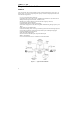
Technical Overview Your DVR can replace both a time-lapse VCR and a multiplexer in a security installation. However, it has many features that make it much more powerful and easier to use than even the most advanced VCR. The DVR converts analog NTSC or PAL video to digital images and records them on a hard disk drive. Using a hard disk drive allows you to access recorded video almost instantaneously; there is no need to rewind tape.
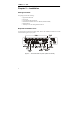
TVDR4 – 9 – 16H Chapter 2 — Installation Package Contents The package contains the following: • • • • • • Digital Video Recorder Power Cord User’s Manual (This Document) RAS Software Diskettes and User’s Manual (Premium Model) Rack-mount Kit Assembly Screws for Adding Hard Disk Drives Required Installation Tools No special tools are required to install the DVR. Refer to the installation manuals for the other items that make up part of your system. Figure 2 — 16-Channel DVR rear panel.
Setting Unit for NTSC or PAL Figure 3 — NTSC/PAL switch. Your DVR can be used with either NTSC or PAL equipment. Before turning on the DVR, set the switch to NTSC or PAL to match your equipment. NOTE: You cannot mix NTSC and PAL equipment. For example you cannot use a PAL camera and an NTSC monitor. CAUTION: If you set the switch from NTSC (PAL) to PAL (NTSC), please do the Factory Reset and Clear All Data. If not, it causes the DVR to perform wrong operations.
TVDR4 – 9 – 16H Connecting the Monitor Figure 6 — Video Out connectors. Connect the monitor to either the Video Out or SVHS Out connector. NOTE: If your monitor has an SVHS input, use it because it will give you better quality video display. NOTE: The Video Out (BNC) and the SVHS Out connectors may be connected to individual monitors for simultaneous operation. Connecting Audio NOTE: It is the user’s responsibility to determine if local laws and regulations permit recording audio.
NOTE: To make connections on the Alarm Connector Strip, press and hold the button and insert the wire in the hole below the button. After releasing the button, tug gently on the wire to make certain it is connected. To disconnect a wire, press and hold the button above the wire and pull out the wire. AI 1 to 16 (Alarm In) You can use external devices to signal the DVR to react to events. Mechanical or electrical switches can be wired to the AI (Alarm In) and GND (Ground) connectors.
TVDR4 – 9 – 16H Connecting to the RS485 Figure 10 — RS485 Connector. The DVR can be controlled remotely by an external device or control system, such as a control keyboard, using RS485 half-duplex serial communications signals. The RS485 connector can also be used to control PTZ (pan, tilt, zoom) cameras. Connect RX+, RX-, TX+ and TX- of the control system to the TX+, TX-, RX+ and RX- (respectively) of the DVR.
Connecting the Printer Figure 13 — Printer connector. You can print images from your DVR on PostScript™ printers. The DVR supports PostScript™ 2.0 and higher. If you have a color PostScript™ printer, you can print color images. Place the printer on a sturdy surface near enough to the DVR so that you will be able to make the cable connections. Connect the DB-25P end of the cable to the DB-25S Printer connector on the back of the DVR. Connect the other end of the cable to the printer.
TVDR4 – 9 – 16H Factory Reset Figure 15 — Factory reset switch. The DVR has a Factory Reset switch to the right of the RS232 connector. This switch will only be used on the rare occasions that you want to return all the settings to the original factory settings. CAUTION: When using the Factory Reset, you will lose any setting you have made. To reset the unit, you will need a straightened paperclip: 1. Turn the DVR off. 2. Turn it on again. 3.
WARNING: ROUTE POWER CORDS SO THAT THEY ARE NOT A TRIPPING HAZARD. MAKE CERTAIN THE POWER CORD WILL NOT BE PINCHED OR ABRADED BY FURNITURE. DO NOT INSTALL POWER CORDS UNDER RUGS OR CARPET. THE POWER CORD HAS A GROUNDING PIN. IF YOUR POWER OUTLET DOES NOT HAVE A GROUNDING PIN RECEPTACLE, DO NOT MODIFY THE PLUG. DO NOT OVERLOAD THE CIRCUIT BY PLUGGING TOO MANY DEVICES IN TO ONE CIRCUIT. Your DVR is now ready to operate. Refer to Chapter 3 — Configuration and Chapter 4 — Operation.
TVDR4 – 9 – 16H Chapter 3 — Configuration NOTE: Your DVR should be completely installed before proceeding. Refer to Chapter 2 — Installation. Front Panel Controls Figure 17 — 16-Channel DVR front panel. (Others are similar.) The front panel looks and operates much like a VCR combined with a multiplexer. Many of the buttons have multiple functions. The following describes each button and control. Take a few minutes to review the descriptions.
MENU Button Pressing the MENU button enters the Quick Setup screen. You will need to enter the administrator password to access the Quick Setup. Pressing the button also closes the current menu or setup dialog box. ALARM Button The ALARM button has two functions. First, it will reset the DVR’s outputs including the internal buzzer during an alarm. Second, it will display the event log when you are in the live monitoring mode unless there is an active alarm. This operation can be user password protected.
TVDR4 – 9 – 16H SEARCH Button Pressing the SEARCH button displays the Search menu. Pressing the button again will exit the Search menu. This operation can be user password protected. Zooms In in PTZ mode. PLAY/PAUSE Button Pressing the PLAY/PAUSE button plays back images at regular speed. Pressing the button while in the playback mode will pause the video. The screen displays when the DVR is playing back video. The screen displays when in the Pause mode. Zooms Out in PTZ mode.
Shuttle Ring The Shuttle Ring only functions in the Playback mode. The Shuttle Ring is spring loaded and returns to the center position when released. Turning the ring clockwise plays video forward. Turning the ring counterclockwise plays video backward. Playback speed varies with the amount the ring is turned. The playback speeds are x0.5, , , , x0.5, , , and . When you release the ring, it snaps back to the center position and the video pauses.
TVDR4 – 9 – 16H CLOCK displays when the digits are displaying the current time. PB displays when video is being played back and the digits are displaying the time of the recording. REMAIN displays when the digits are displaying the remaining hard disk drive capacity. ALARM displays when any camera is in the event-driven recording mode. The bell icon displays during alarm activation. These light when the display is in the remaining disk capacity mode. TB = TeraBytes, GB = GigaBytes and MB = MegaBytes.
Initial Unit Setup Before using your DVR for the first time, you will want to establish the initial settings. This includes items such as time and date, display language, camera, audio, remote control, record mode, network and password. Your DVR can be set up using various screens and dialog boxes. Press the MENU button to enter the setup screens. The Admin Password screen appears. Figure 19 — Admin Password screen.
TVDR4 – 9 – 16H The Quick Setup screen allows you to set up the most commonly used features of your DVR. button lets you make your Use the arrow buttons to move through the options. Pressing the selections. Highlight the box beside Quick Setup and press the button to toggle between On and Off. If you select Off, you will use the Normal Setup screen to change the DVR’s settings. Highlight the Record Speed box and select recording speeds from as few as one image every 10 seconds to as fast as 60 ips.
Normal Setup Screen Figure 21 — Normal Setup screen. Press the MENU button to enter the setup screen. If the Quick Setup screen appears, turn it off as described above. The Normal Setup screen gives you access to all the DVR’s setup screens.
TVDR4 – 9 – 16H System Information Highlight System Information and press the appears. button. The System Information screen Figure 22 — System Information screen. In the System Information screen, you can name the site location, assign a unit ID number and button. The select the language the screens are displayed in. Highlight Change and press the System Information Change screen appears. Figure 23 — System Information Change screen.
Highlight the box beside Unit ID and press the button. Change the number by highlighting it and using the Up and Down arrow buttons to increase and decrease the number. The Unit ID number is used to identify the unit when it is networked with other DVRs. You cannot use the same number for two or more DVRs that are within the same network. Highlight the box beside Language and press button. A dropdown menu displays the available languages. Highlight the desired language and press the button.
TVDR4 – 9 – 16H Once you have entered your title, highlight Close and press the button. Highlight the box beside Unit ID and press the button. Change the number by highlighting it and using the Up and Down arrow buttons to increase and decrease the number. After you have created a title, assigned a unit ID number and selected a language, you can save button. Selecting Cancel exits the screen your changes by highlighting OK and pressing the without saving the changes.
Highlight the box beside Daylight Saving Time and press the toggles between On and Off. button. Pressing the button button. You can set up holidays by Highlight the Holiday Setup… box and press the highlighting Add: and pressing the button. The current date appears. Highlight the month and day and change them by using the Up and Down arrow buttons. Press the button to add the date. Dates can be deleted by highlighting the X beside the date and button.
TVDR4 – 9 – 16H You can save your changes by highlighting OK and pressing the exits the screen without saving the changes. button. Selecting Cancel System Log Screen Highlight System Log in the Main menu and press the appears. button. The System Log screen Figure 28 — System Log screen. The System Log screen displays a record of various events logged by the DVR.
System Check Screen Highlight System Check in the Main menu and press the screen appears. button. The System Check setup Figure 29 — System Check screen. button. This toggles between On Highlight the box under the On/Off heading and press the and Off. When it is On, the DVR reports a fault condition if it does not detect any recording or if there is an alarm during the designated time. Highlight the box under the Interval heading and press the button.
TVDR4 – 9 – 16H Configuring Input Devices You can configure the video, audio and remote control devices connected to the DVR. Figure 30 — Device menu screen. Camera Setup Screen Highlight Camera in the Main menu and press the appears. button. The Camera setup screen Figure 31 — Camera setup screen.
The Camera setup screen displays the camera inputs in groups of four: 1-4, 5-8, 9-12 and 13-16. In this screen you can tell the DVR which input connectors have cameras attached by turning the camera number On or Off. You can assign titles to each camera by highlighting the camera title box and pressing the button. A virtual keyboard allows you to enter camera names. Selecting the PTZ Device box causes a list of controllable cameras to display. Select your camera from the list and press the button.
TVDR4 – 9 – 16H Alarm In Setup Screen Highlight Alarm In in the Main menu and press the appears. button. The Alarm In setup screen Figure 33 — Alarm In setup screen. The alarm terminal strip on the back of the DVR has inputs associated with each alarm. You can set up each input on the Alarm In Setup screen. The inputs are displayed in groups of four. You can turn each input On or Off. Each input can be given a title, and the inputs can be set as NO (normally open) or NC (normally closed) independently.
Your DVR has built-in video motion detector. Video motion detector can be turned On or Off for each camera. Highlighting the box under the Sensitivity heading allows you to adjust the DVR’s sensitivity to motion. There are five settings with 1 being the least sensitive and 5 being the most sensitive. You can adjust the minimum number of detection blocks that must be activated to trigger a motion alarm. Highlight a box under the Min Size heading and adjust the number.
TVDR4 – 9 – 16H Select All Blocks — Activates all blocks to detect motion. Clear All Blocks — Deactivates all blocks so that they will not detect motion. Reverse All Blocks — Activates inactive blocks and deactivates active blocks. Exit Zone Setup — Asks you to confirm changes and then returns to the previous screen. Alarm Out Setup Screen The Alarm Out setup screen allows you to establish a schedule for each alarm output from the DVR. Figure 36 — Alarm Out setup screen.
Figure 37 — Alarm Out Schedule screen. You can select individual blocks of time, entire days of the week, entire blocks of time or the entire schedule. Select a specific block of time by highlighting it. Select an entire day by highlighting the day of the week or Holiday on the left of the screen. Select an entire block of time by highlighting the time at the top of the screen. Select the entire screen by highlighting the button from No Arming (no block) empty box in the upper left corner of the screen.
TVDR4 – 9 – 16H Audio Setup Screen Highlight Audio in the Main menu and press the button. The Audio Setup screen appears. Figure 38 — Audio Setup screen. Highlight the box beside Audio Recording and press the button. This toggles between On and Off. When it is On, the DVR also records audio when it is recording video. button. This toggles between On and Off. When Highlight the box beside Mute and press the it is On, the DVR will NOT play live or recorded audio. button toggles between Mic In and Line In.
RS232/RS485 Setup Screen The RS232/RS485 setup screen allows you to set up the RS232 and RS485 ports to communicate with external devices such as modems, remote controls and dome cameras. Figure 39 — RS232/RS485 setup screen. Highlight the field for the settings you wish to make. Select the correct Baud Rate, Parity, Data Bits and Stop Bits for the device you are connecting to the DVR. For RS485, it is possible to select either Remote Control or PTZ Control in the Usage field.
TVDR4 – 9 – 16H Configuring Recording Settings NOTE: Pressing the REC button on the front of the DVR will cause the red LED to light and indicates the DVR is ready to record. However, this does not mean the DVR is recording. The DVR records video based on the parameters such as schedule and events defined during configuration. The record indicator on the front display panel lights when the DVR is recording. Your DVR offers a variety of flexible recording modes.
Highlight the box beside Mode. Pressing the button toggles between Simplex and Duplex. In the Simplex mode, the DVR can record up to 60 images per second for NTSC (50 for PAL). However, in the Simplex mode, you can only record or play back video, but not both. In the Duplex mode, you can record and play back video at the same time. However, you can only record up to 30 images per second for NTSC (25 for PAL) while in the Duplex mode.
TVDR4 – 9 – 16H Highlight the box under Quality and press the button. A drop-down list appears. You can select from Very High, High, Standard and Low image quality. All other variables being equal; Very High will require 600% more hard disk space than Standard, High will require 250% more, and Low 30% less. NOTE: Higher quality images require more storage space and will reduce the recording capacity of the hard disk drive. You can set the maximum amount of time-lapse video to be stored.
There are several ways to set recording times: • You can highlight an individual block and toggle it On or Off by pressing the button. • You can change a 30-minute segment for all days by placing the cursor on the time line and pressing the button to toggle the segment On or Off. • You can change an entire day by placing the cursor on the day of the week and pressing the button to toggle the day On or Off.
TVDR4 – 9 – 16H You can set the amount of time to record prior to the event by adjusting the Dwell. You can set the Dwell from 1 to 300 seconds. NOTE: When the DVR is in the Time-Lapse mode, it ignores the pre-event settings and follows the time-lapse settings. Event Action Setup Highlight the Alarm In Event Action, Motion Detector Event Action, or Video Loss Event Action in the Main menu. The following Event Action setup screens will appear.
Highlight the Quality box and select the image quality you want to record from the drop-down menu. Highlight the Dwell box and set the length of time you would like to record for the associated event. Alarm In Event Action (Alarm Out) Setup Screen The DVR can be set to react to events differently by activating an internal buzzer or external alarms. Figure 45 — Alarm In Event Action (Alarm Out) setup screen. Highlight the Sched box and press the as described earlier. button. A schedule screen appears.
TVDR4 – 9 – 16H Alarm In Event Action (Notify) Setup Screen The DVR can be set to notify the remote site when certain events are activated. (Premium Model Only) Figure 46 — Alarm In Event Action (Notify) setup screen. Highlight the Sched box and press the as described earlier. button. A schedule screen appears. Set the schedule Highlight the Notify box and press the button. This toggles between On and Off.
Motion Detector Event Action (Record) Setup Screen The DVR can be set to react to motion detector differently. Each camera can be assigned a schedule, associated camera, recording speed, video quality and dwell time. Figure 47 — Motion Detector Event Action (Record) setup screen. Highlight the Sched box and press the as described earlier. button. A schedule screen appears. Set the schedule Highlight the Camera box and press the button. A camera selection screen appears.
TVDR4 – 9 – 16H Motion Detector Event Action (Alarm Out) Setup Screen The DVR can be set to react to motion events differently by activating an internal buzzer or external alarms. Figure 48 — Motion Detector Event Action (Alarm Out) setup screen. Highlight the Sched box and press the as described earlier. button. A schedule screen appears. Set the schedule Highlight the Alarm-Out box and either Beep or the alarm output terminal that you want to associate with the motion event.
Motion Detector Event Action (Notify) Setup Screen The DVR can be set to notify the remote site when certain motion events are activated. (Premium Model Only) Figure 49 — Motion Detector Event Action (Notify) setup screen. Highlight the Sched box and press the as described earlier. button. A schedule screen appears. Set the schedule Highlight the Notify box and press the button. This toggles between On and Off.
TVDR4 – 9 – 16H Video Loss Event Action (Record) Setup Screen The DVR can be set to react to video loss from a camera differently. Each camera can be assigned a schedule, associated camera, recording speed, video quality and dwell time. Figure 50 — Video Loss Event Action (Record) setup screen. Highlight the Sched box and press the as described earlier. button. A schedule screen appears. Set the schedule Highlight the Camera box and press the button. A camera selection screen appears.
Video Loss Event Action (Alarm Out) Setup Screen The DVR can be set to react to video loss differently by activating an internal buzzer or external alarms. Figure 51 — Video Loss Event Action (Alarm Out) setup screen. Highlight the Sched box and press the as described earlier. button. A schedule screen appears. Set the schedule Highlight the Alarm-Out box and either Beep or the alarm output terminal that you want to associate with the camera that has lost video.
TVDR4 – 9 – 16H Video Loss Event Action (Notify) Setup Screen The DVR can be set to notify the remote site in the case of video loss. (Premium Model Only) Figure 52 — Video Loss Event Action (Notify) setup screen. Highlight the Sched box and press the as described earlier. button. A schedule screen appears. Set the schedule button. This toggles between On and Off.
OSD (On-Screen Display) Setup The DVR can be set up to display Date, Time, Title and Status on screen. Each feature can be turned on or off, and you can adjust the margins. Figure 53 — OSD Setup screen. Highlight the box beside Date and press the button to toggle the date display On and Off. Highlight the box beside Time and press the button to toggle the time display On and Off. Highlight the box beside Title and press the Off.
TVDR4 – 9 – 16H Sequence Display Setup Screen You can adjust the display dwell time for each camera when the DVR is setup to sequence through the cameras. You can also turn Camera Sequence On and Off. Figure 54 — Sequence Display setup screen. Highlight the box beside Sequence Dwell Time and press the display dwell time from 3 to 60 seconds. Highlight the box beside Sequence in Cameo and press the and Off. (Not on 4-camera model.) button.
Network Setup Screen NOTE: The network features can be set only on the Premium Model DVR. The network features are “grayed” out and inactive on the non-Premium Model. In the Network Setup screen you can set up the DVR for LAN connections. Figure 55 — Network Setup screen. Highlight the box beside Connection. Press the button to toggle between LAN and Modem. Highlight the box beside Admin Password and press the button. A virtual keyboard appears. You will first be asked to enter the current password.
TVDR4 – 9 – 16H CAUTION: Write the password down and keep it in a safe place. Once the password has been reset, the default will no longer work. If the password is forgotten, the unit must be reset using the Factory Reset Button and all data settings will be lost. LAN Setup Screen Figure 56 — LAN Setup screen. NOTE: You will need to get the appropriate IP Address, Gateway and Subnet Mask from your network administrator.
Modem Setup Figure 57 — RS232/RS485 setup screen. NOTE: Modem setup is done through the RS232/RS485 screen in the Devices menu which can be accessed from the Main Menu. Highlight the box beside Baud Rate of the RS232 field and press the rates ranging from 300 to 115,200 appears. Highlight the box beside Parity of the RS232 field and press the appears. You can select from None, Odd or Even parity. button. A list of baud button. A drop-down list Highlight the box beside Data Bit of the RS232 field.
TVDR4 – 9 – 16H Callback Center (LAN) Setup Screen Figure 58 — Callback Center (LAN) Setup screen. The DVR can be set up to contact a computer running RAS (Remote Administration System) on a LAN when an event occurs. Highlight the box beside IP Address and enter the IP address of the computer you want contacted during an event. Highlight the box beside Retry and enter the number of times you would like the DVR to try contacting the computer. You can select from 1 to 10 retrys.
Callback Center (Modem) Setup Screen Figure 59 — Callback Center (Modem) Setup screen. If you have a modem connected to the DVR, it can be set up to dial a pager with a numeric message when an event occurs. NOTE: The DVR will wait for at least one minute between pages. If another event occurs less than one minute after the DVR has notified a pager, it will not dial the pager. It does this so that the telephone line will not be tied up.
TVDR4 – 9 – 16H Password Setup Screen An Administrator password is required to turn the system off, enter the setup screen, load default setups, clear all data, change system date and time and change the Administrator password. Highlight Password in the Main menu and press to enter the Password screen. Figure 60 — Password setup screen. Highlight the box beside User and press the button to toggle between On and Off.
To lock front panel buttons, highlight Key Lock On and press the button. Once the buttons are locked, pressing any front panel button will cause a password screen to display. You will need to enter the correct password to unlock the keys. The Key Lock password is 4231. You can save your changes by highlighting OK and pressing the screen without saving the changes. button.
TVDR4 – 9 – 16H Backup The Backup screen can be used to back up video to an external USB hard disk drive. Figure 62 — Backup screen. The default video segment to be backed up is from the first to last frame. However, you can define how much video to back up by changing the start and end times and dates. You will need to enter a file name before the video will back up. A virtual keyboard appears allowing you to enter a file name.
Chapter 4 — Operation NOTE: This chapter assumes your DVR has been installed and configured. If it has not, please refer to Chapters 2 and 3. The DVR’s controls are similar to a VCR. As with a VCR, the main functions are recording and playing back video. However, you have much greater control over recording and playing back video. You can establish recording schedules based on time of day and day of the week.
TVDR4 – 9 – 16H PIP Mode You can display a Picture-in-Picture by pressing the DISPALY button. You can change the location of the PIP by pressing the Up and Down arrow buttons and its size by pressing the Left and Right arrow buttons. PTZ Mode The DVR will control cameras with Pan, Tilt and Zoom capabilities. Press the PTZ button to enter the PTZ mode. You can control the camera using front panel control buttons or by setting up presets.
You can save camera position settings as “presets” so that you can go directly to desired views. Once you have the camera at the desired settings, press the STOP button, and the PTZ Preset dialog box will appear. Select the number you want to assign to the preset and press the button. Use the virtual keyboard to enter the preset name. Press the REC button to load the PTZ preset and the Preset View dialog box will appear. Select the desired preset and press the button to load the preset.
TVDR4 – 9 – 16H Playing Recorded Video Once video has been recorded, you can view it by pressing the PLAY/PAUSE button. When playing video for the first time, the DVR will display the most recent image. When playing video subsequent times, the DVR will start playing video from the last recalled image. NOTE: If the DVR is set in the Simplex mode, you will need to stop recording before playing back video. Pressing the PLAY/PAUSE button again will freeze the video on the screen.
Shuttle Ring The Shuttle Ring only functions in the Playback mode. The Shuttle Ring is spring loaded and returns to the center position when released. Turning the ring clockwise plays video forward. Turning the ring counterclockwise plays video backward. Playback speed varies with the amount the ring is turned. The playback speeds are x0.5, , , , x0.5, , , and . When you release the ring, it snaps back to the center position and the video pauses.
TVDR4 – 9 – 16H Date/Time Search Figure 66 — Date/Time Search screen. Move the cursor over the date and press the button. You can use the Left and Right arrow buttons to highlight the year, month and day. Use the Up and Down arrow buttons to change to button. the date you want to search for video. Once you have set the date you want, press the Move the cursor over the time and press the button. You can use the Left and Right arrow buttons to highlight the hour, minutes and seconds.
Days with recorded video display on the calendar with white numbers. You can highlight the days with recorded video by using the arrow buttons. Once you have highlighted a day, press the button to select it. A time bar will display at the bottom of the calendar. Hours in which video was recorded will be highlighted. You can use Up and Down arrow buttons to highlight the time bar. Once the time bar is highlighted, you can select the time by using the Left and Right arrow buttons.
TVDR4 – 9 – 16H Figure 69 — Event Search (by Camera) screen. Figure 70 — Event Search (by Event) screen. Highlight the box beside Search by and press the Event. button to toggle between Camera and You can search video from the first to last recorded images, or you can set the start and stop times and dates. When you select the Search by Camera, select the target cameras and event options. When you select the Search by Event, select event options for each device.
Printing Figure 71 — Print screen. It is possible to print images to a PostScript™ printer. Pause the video on the desired image and press the SEARCH button. Select Print… from the menu, and the Print screen appears. The date and time of the paused images displays in the Last Played Image Time box. Selecting Start will begin printing the image. Archiving Figure 72 — Backup screen.
TVDR4 – 9 – 16H It is possible to archive video to an external USB-IDE hard disk drive. The archived images can be viewed on computers running Microsoft Windows 98, ME or 2000. Refer to the Appendix A — USB Hard Disk Drive Preparation for information on preparing the external drive for archiving. CAUTION: Do NOT disconnect the USB cable or the power from the external drive while archiving video.
Appendix A — USB Hard Disk Drive Preparation Preparing the USB-IDE hard disk drive in Windows2000 1. Connect the USB-IDE hard disk drive to your computer using the USB Cable. 2. Turn on your computer. 3. The USB device icon should display on the Taskbar. 4. If the USB-IDE hard disk drive is partitioned or has data, it will show up in My Computer as a hard disk drive icon. Check the file system by right clicking on the icon and checking under Properties > General > File System.
TVDR4 – 9 – 16H 4. If the USB-IDE hard disk drive is partitioned or contains data, it will show up in My Computer as a hard disk drive icon. Check the file system in Properties > General > File System. If the file system is NOT FAT32 format, format the USB-IDE hard disk drive with FAT32 format. 5. Run the FDISK utility by clicking Start then RUN. Type “fdisk” and click OK. 6. When the MS-DOS command prompt appears, type “Y” and hit the enter key. 7. In the FDISK Option menu, choose “5.
Appendix B — Reviewing Backup Images Disconnect the external USB-IDE hard disk drive from the DVR, and connect it to your PC. You do not need to install any special software on your personal computer to review the video. The backup file contains the Player program. Double-clicking the target backup file starts the Player program. NOTE: It is suggested that the computer used for the Player program has at least a 800MHz Pentium III.
TVDR4 – 9 – 16H The Brightness Control Slide Bar adjusts the brightness of the backup images by clicking the mouse and dragging along the slider bar. Minute brightness change can be made by using the arrow buttons located at each end of the bar. The Brightness Revert Button reloads to the original image. Clicking the OSD (On-Screen Display) Button switches the OSD option. The OSD information includes camera location and date/time.
Appendix C — Troubleshooting Problem Possible Solution No Power • Check power cord connections. • Confirm that there is power at the outlet. No Live Video • Check camera video cable and connections. • Check monitor video cable and connections. • Confirm that the camera has power. • Check camera lens settings. Live Video Very Bright If a cable is attached to the “Loop” connector, make certain it is connected to a properly terminated device.
TVDR4 – 9 – 16H Appendix D — Connector Pin Outs I/O Connector Pin Outs AI (1 to 16) GND Alarm Inputs 1 to 16 Chassis Ground (4 connectors) AO (1 to 4) ARI Alarm Outputs 1 to 4 Alarm Reset In RS485 Connector Pin Outs Master Unit 72 Slave Unit RX+ → To → TX+ RX- → To → TX- TX+ → To → RX+ TX- → To → RX-
Appendix E — Map of Screens MENU System System Information Date/ Time System Check System Log Device Camera Alarm- In Motion Detector Alarm- Out Audio RS232/ RS485 Record Record Mode Time Lapse Record Pre- Event Record Event Action Alarm- In Action Motion Action Video Loss Action Display OSD Sequence Display Network Network Setup Callback Center Password Configuration Quick Setup Backup Load Default Setup Clear All Data 73
TVDR4 – 9 – 16H Appendix F — Specifications Signal Format Video Input Monitor Outputs Video Resolution Playback/Record Speed (images per second) Alarm Input Alarm Output Alarm Reset Input Network Connectivity (Premium Model only) Audio Input Audio Output Video Input Video Loop Monitor Output Audio In Audio Out Alarms Ethernet Port RS232 Serial Port RS485 Serial Port USB Port VIDEO NTSC or PAL (selector switch) Composite: 4, 9 or 16 looping inputs, 1 Vp-p, auto-terminating, 75 Ohms Composite: One, 1 Vp-p,
STORAGE EIDE hard disk drive (up to 4) USB Primary Storage Backup Storage Dimensions (W x H x D) Unit Weight Shipping Weight Shipping Dimensions (W x H x D) Operating Temperature Operating Humidity Power FCC CE UL GENERAL 16.9" x 3.5" x 14.4" (430mm x 88mm x 365mm) 20.9 lbs. (9.45kg) 24.1 lbs. (10.95kg) 21.5" x 11.2" x 19.