™ USE OF FOUNDATION FIELDBUS PROTOCOL and PROFIBUS PA WITH PASSIVE SONAR PROCESS FLOW MONITORING TRANSMITTERS CiDRA Corporate Services Tel. 203-265-0035 50 Barnes Park North Fax. 203-294-4211 Wallingford, CT 06492 www.cidra.
Table of Contents 1 USE OF FOUNDATION FIELDBUS AND PROFIBUS PA WITH PASSIVE SONAR PROCESS FLOW MONITORING SYSTEMS ............................................................................. 1-1 1.1 Introduction................................................................................................................... 1-1 2 FOUNDATION FIELDBUS and PROFIBUS PA BLOCK DEFINITIONS.......................... 2-1 2.1 Resource Blocks ..........................................................................
***This Page Left Blank*** Copyright © 2010 CiDRA Corporate Services Page ii 20958-01 Rev 02
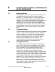
1 USE OF FOUNDATION FIELDBUS AND PROFIBUS PA WITH PASSIVE SONAR PROCESS FLOW MONITORING SYSTEMS 1.1 Introduction This document is intended as an overview of configuration and use of FOUNDATION Fieldbus and Profibus PA on the passive sonar process flow monitoring system transmitter. National Instruments Configurator will be used to demonstrate the functionality available using FOUNDATION Fieldbus protocol, but other Fieldbus configuration tools may also be used. Refer to Appendix A for example.
***This Page Left Blank*** Copyright © 2010 CiDRA Corporate Services Page 1-2 20958-01 Rev 02
2 FOUNDATION FIELDBUS and PROFIBUS PA BLOCK DEFINITIONS 2.1 Resource Blocks Resource blocks contain the hardware specific characteristics associated with a device; they have no input or output parameters. The algorithm within a resource block monitors and controls the general operation of the physical device hardware. The execution of this algorithm is dependent on the characteristics of the physical device, as defined by the manufacturer.
2.4 Analog Output Blocks The Analog Output (AO) function block assigns an output value to a field device through a specified I/O channel. The block supports mode control, signal status calculation, and simulation. 2.5 PID Block A Proportional/Integral/Derivative (PID) Function Block is not available.
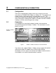
3 CONFIGURATION & CONNECTION 3.1 Configuration There are no configuration settings necessary on the passive sonar transmitter for FOUNDATION Fieldbus or Profibus PA. The protocol itself enables devices to be automatically assigned addresses, etc. The transmitter firmware forces communication to be set to the required baud rate to work with the Softing FBK Fieldbus or Profibus interface hardware. Loading an INI file cannot change these settings. 3.
***This Page Left Blank*** Copyright © 2010 CiDRA Corporate Services Page 3-2 20958-01 Rev 02
4 MAKING CHANGES to TRANSMITTER USING A FIELDBUS HOST To change the configuration to the transmitter using a Fieldbus or Profibus Host, perform the following steps: Place the Transducer Block Out Of Service (OOS) Write any changes to the variables in the Transducer Block Place the Transducer Block to Auto Mode When transmitter is placed into Auto Mode, it will validate any changes made. Invalid changes will be returned to their previous value.
***This Page Left Blank*** Copyright © 2010 CiDRA Corporate Services 20958-01 Rev 02 Page 4-2
5 INPUT, OUTPUT AND TRANSDUCER BLOCKS 5.1 Analog Input Blocks The following table lists the analog input blocks. Channel 1 2 3 4 5 6 7 8 9 5.2 Analog Input Block Data Type FLOW_RATE Float GVF Float SOS Float SENSORHEAD_TEMPERATURE Float TOTAL_FLOW Float OUTPUT_1 Float OUTPUT_2 Float OUTPUT_3 Float OUTPUT_4 Float Table 1 Analog Input Blocks Analog Output Blocks The following table lists the analog output blocks. Channel 10 11 12 13 14 5.
Table 3 Parameter / Structure Name CONTROL Transducer Block Configurations Data Type Access Help WRITE_CONTROL Unsigned16 R/W RESET_TOTALIZER CLEAR_ALARM CLEAR_DATA_HISTORY Unsigned16 Unsigned16 Unsigned16 R/W R/W R/W Controls ability to write and commit changes to transmitter configuration. Resets all totalizers to zero. Clear any existing alarms. Clears the data history memory.
Table 3 PIPE_WALL_THICKNESS PIPE_SIZE PIPE_SCHEDULE SOS_PIPE_WALL_THICKNESS_UNITS SOS_PIPE_WALL_THICKNESS Transducer Block Configurations (Page 2) Float R/W Pipe wall thickness measurement in selected units. Unsigned Selects pipe size. Will only be applied if 'Size / R/W Char Schedule' is selected for 'Pipe Diameter Input Mode'. Unsigned Selects pipe schedule. Will only be applied if 'Size / R/W Char Schedule' is selected for 'Pipe Diameter Input Mode'.
Table 3 Transducer Block Configurations (Page 3) ENVIRONMENT SOS_TEMPERATURE_INPUT_SELECTION Unsigned Char SOS_PRESSURE_INPUT_SELECTION Unsigned Char SOS_TEMPERATURE_UNITS SOS_PRESSURE_UNITS Unsigned Char Unsigned Char R/W R/W R/W R/W Selects the source of the temperature used in GVF calculations. 'Fixed' uses 'SOS Process Temperature'* 'Sensor 1' uses the 4-20mA input channel 1* 'Sensor 2' uses 4-20mA input channel 2* Protocol uses values written to Fieldbus AO Channel 11.
Table 3 FLOW_HIGH_CUTOFF_PCT FLOW_CUSTOM_BASE_VOLUME_UNIT FLOW_CUSTOM_BASE_TIME_UNIT FLOW_CUSTOM_VOLUME_UNIT_LABEL FLOW_CUSTOM_TIME_UNIT_LABEL FLOW_CUSTOM_VOLUME_UNIT_MULTIPLIER FLOW_CUSTOM_TIME_UNIT_MULTIPLIER FLOW_QUALITY_DELTA GVF_DECIMAL_PLACES SOS_MEASUREMENT_UNITS SOS_QUALITY_DELTA Transducer Block Configurations (Page 4) High flow cutoff as a % of flow measurement range Float R/W (defined by Flow Min and Flow Max). Will not display or output flow reading if flow rate is above this setting.
Table 3 UPDATE_RATE SENSORS_IN_USE TRANSMITTER_GAIN Transducer Block Configurations (Page 5) Sets transmitter update rate. Defines time units in number of blocks. This parameter will set the update rate in seconds (nominally). Actual update rate (in Unsigned R/W seconds) can be calculated by taking (BLOCK_SIZE / Long SAMPLE_FREQ) * UPDATE_RATE (VF mode) or (BLOCK_SIZE / SOS_SAMPLE_FREQ) * UPDATE_RATE (SOS mode). Unsigned Long Float R/W Sets number of sensors. Always leave set to 8.
Table 3 SPL_STD_DEV Transducer Block Configurations (Page 6) Float R The standard deviation of the SPL measurements from all active sensors. Unsigned Char R/W Gain selection for the preamp.
Table 3 FLOW_NYQUIST_HIGH FLOW_NYQUIST_LOW FLOW_CENTROID_WIDTH FLOW_VEL_SEARCH_LIMIT_LOW FLOW_VEL_SEARCH_LIMIT_HIGH FLOW_NYQUIST_INITIAL_VALUE FLOW_DECIMATION FLOW_WINDOW_TYPE FLOW_DETREND Transducer Block Configurations (Page 7) Define high end of frequency range to use for determining flow velocity. Defined by: Float R/W FREQUENCY_MAX = (Measured Velocity * VF_NYQUIST_HIGH) / Sensor Spacing. Example: (10 ft/sec*0.7) / 0.
Table 3 Transducer Block Configurations (Page 8) FLOW_NORMALIZATION Unsigned Long R/W FLOW_DIFFERENCING Unsigned Long R/W FLOW_DIRECTION Unsigned Long R/W FLOW_WINDOW_SIZE_MULTIPLIER Unsigned Long R/W FLOW_PEAK_SEARCH_MODE Unsigned Long R/W FLOW_OPERATING_MODE Unsigned Long R/W FLOW_QUALITY_MODE Unsigned Long R/W FLOW_DATA_LENGTH Unsigned Long R/W FLOW_WINDOW_SIZE Unsigned Long R/W Enable/disable normalization of sensor data. 0 - No normalization* 1 - Normalize data.
Table 3 FLOW_WINDOW_OVERLAP FLOW_WINDOW_AVERAGES FLOW_CALIBRATION FLOW_CAL_COEFF_C0 FLOW_CAL_COEFF_C1 FLOW_CAL_COEFF_C2 Transducer Block Configurations (Page 9) Unsigned Define overlap of FFT windows. This value is normally R/W Long set by DSP to half of NFFT. Default values are normally OK. In general* for slower flow rates* use more FFT averages* for faster flow Unsigned rates* use fewer FFT averages.
Table 3 SOS_MIN Transducer Block Configurations (Page 10) Float R/W SOS_MAX Float R/W SOS_MIN_QUALITY Float R/W SOS_CENTROID_WIDTH Float R/W SOS_FREQUENCY_THRESHOLD Float R/W Minimum SOS value to search for. If too much energy (such as from a high velocity vortical ridge) causes the algorithms to calculate a sound speed below that of the main SOS ridge* this parameter may need to be increased. Care must be taken not to set this higher than the expected minimum SOS for the application.
Table 3 Transducer Block Configurations (Page 11) SOS_TOTAL_DATA Unsigned Long R/W SOS_WINDOW_SIZE Unsigned Long R/W SOS_WINDOW_OVERLAP Unsigned Long R/W SOS_SUB_ARRAY_SIZE SOS_NORMALIZATION Unsigned Long Unsigned Long R/W R/W SOS_DIFFERENCING Unsigned Long R/W SOS_OPERATING_MODE Unsigned Long R/W SOS_SELECTION_THRESHOLD Unsigned Long R/W SOS_MIN_FREQ_POINTS_(AUTO_FREQ) Unsigned Long R/W Calculates SOS Samples from this value and SOS Sample Frequency: SOS Samples = SOS Total Data *
Table 3 Transducer Block Configurations (Page 12) ANALOG_SECTION ANALOG_SENSOR_INPUT_UNITS_1 ANALOG_SENSOR_INPUT_UNITS_2 ANALOG_SENSOR_INPUT_SCALE_1 ANALOG_SENSOR_INPUT_SCALE_2 ANALOG_SENSOR_INPUT_OFFSET_1 ANALOG_SENSOR_INPUT_OFFSET_2 ANALOG_SENSOR_1_1ST_ORDER_DAMPING_FILTER_ENABLE ANALOG_SENSOR_2_1ST_ORDER_DAMPING_FILTER_ENABLE Unsigned Char Unsigned Char Float Float Float Float Unsigned Char Unsigned Char R/W R/W R/W R/W R/W R/W R/W R/W ANALOG_SENSOR_1_DAMPING_TAU Float R/W ANALOG_SENSOR_2_DAMPING
Table 3 Transducer Block Configurations (Page 13) Unsigned FILTER_FLOW_NR_FILTER_MAGNITUDE_SELECTION R/W Char Selects flow noise reduction filter magnitude. FLOW_DAMPING_FILTER FILTER_FLOW_1ST_ORDER_DAMPING_FILTER_ENABLE FILTER_FLOW_DAMPING_TAU Unsigned Char Float R/W R/W Enables or disables flow 1st order damping filter. Sets tau value for flow 1st order damping filter.
Table 3 Transducer Block Configurations (Page 14) After 'Percent Len' measurements with good quality have been displayed a new measurement with good quality is deemed valid and displayed when the difference between the maximum and minimum of the FILTER_FLOW_SPIKE_FILTER_PERCENTAGE Float R/W present measurement and ('Percent Len' - 1) previous consecutive measurements is less than the measurement range (default of 27fps for Flow) times ('Percent' / 100).
Table 3 FILTER_GVF_SPIKE_FILTER_LENGTH FILTER_GVF_SPIKE_FILTER_UP_COUNT Transducer Block Configurations (Page 15) This parameter is used when the device is 'Holding' a previous measurement due to a new measurement with Unsigned bad quality. The definition of this parameter is the R/W Char required number of consecutive measurements with bad quality before the device enters the 'No Flow' state and displays dashes.
Table 3 Transducer Block Configurations (Page 16) SENSOR SENSORHEAD_SERIAL_NUMBER Octet String R/W SENSOR_THRESHOLD_MAX Long R/W SENSOR_THRESHOLD_MIN Long R/W SENSOR_SPACING SENSOR_1_LOCATION SENSOR_SPACING_1_2 SENSOR_SPACING_1_3 SENSOR_SPACING_1_4 SENSOR_SPACING_1_5 SENSOR_SPACING_1_6 SENSOR_SPACING_1_7 SENSOR_SPACING_1_8 Float Float Float Float Float Float Float Float R/W R/W R/W R/W R/W R/W R/W R/W Starting point for sensor 1. Typically 0. Distance in feet between sensor 1 and sensor 2.
Table 3 Transducer Block Configurations (Page 17) TEMPERATURE Float R SOS_QUALITY SOS_UNFILTERED SOS_FLOW_RATE SOS_FLOW_QUAL TLF TOTAL_TLF TLF_UNFILTERED ANALOG_4_20MA_INPUT_1 ANALOG_4_20MA_INPUT_2 Float Float Float Float Float Float Float Float Float R R R R R R R R R TOTAL_FLOW_FRACTION Float R TOTAL_TLF_FRACTION Float R TOTAL_FLOW_CARRY TOTAL_TLF_CARRY SYSTEM_STATUS SENSOR_MAX_MIN SENSOR_1_MAX SENSOR_2_MAX SENSOR_3_MAX SENSOR_4_MAX SENSOR_5_MAX SENSOR_6_MAX SENSOR_7_MAX SENSOR_8_MAX SENSOR_
Table 3 SENSOR_3_MIN SENSOR_4_MIN SENSOR_5_MIN SENSOR_6_MIN SENSOR_7_MIN SENSOR_8_MIN Transducer Block Configurations (Page 18) Long R Sensor 3 minimum in A/D bins. Long R Sensor 4 minimum in A/D bins. Long R Sensor 5 minimum in A/D bins. Long R Sensor 6 minimum in A/D bins. Long R Sensor 7 minimum in A/D bins. Long R Sensor 8 minimum in A/D bins.
***This Page Left Blank*** Copyright © 2010 CiDRA Corporate Services Page 5-20 20958-01 Rev 02
Appendix A EXAMPLE OF USING FOUNDATION FIELDBUS HOST A1 Connection Setup The following hardware was used for this example of a connection setup: Softing FG-100 FF/HSE Linking Device Relcom FCS-PH-PL Fieldbus Power Hub 24V Bench power supply Transmitter with Fieldbus The hardware was connected as follows: Fieldbus Ethernet PC Linking Device Power Hub 24V Fieldbus Bench Supply Figure 2 A2 SONARtrac Example Connection Setup Using National Instruments Configurator Tools provided by Nationa
Prior to connecting the transmitter to the Fieldbus, the Configurator will show a screen similar to the following: Figure 3 NI-FBUS Configurator Once connected, a process will start where an address will be assigned to the transmitter. This may take few minutes.
Figure 6 NI-FBUS Configurator Display Example Opening the SONAR object by clicking on the ‘+’ sign will open up all the included ‘Function Blocks’ available: Figure 7 Opening Function Blocks Example Copyright © 2010 CiDRA Corporate Services 20958-01 Rev 02 Page A-3
Note: For this example descriptive names have been given to the device. By default, the Function Blocks will be given generic names. On the setup an image to be displayed has been assigned and the manufacturer info file (“mfr_info.txt”, part of the Configurator program), which includes information about SONARtrac and CiDRA has been modified.
A3 Changing Settings With Configurator Double-clicking on the ‘Configuration (STB)’ or ‘Transducer Block’ brings up the following dialog: Figure 9 Configuration (STB) Example Clicking on the ‘Others’ tab and expanding the window will list all the available settings for the transmitter shown on the following page. The full list is found in Section 5.
Figure 10 Partial List of Available Settings Copyright © 2010 CiDRA Corporate Services Page A-6 20958-01 Rev 02
The top-left of the window shows the current state of the Transducer Block – OOS (Out Of Service) or Auto: Figure 11 Transducer Block State ‘Auto’ indicates the device is running normally. The bulk of the window lists the parameters, grouped by function, their current value, the type and help text, as read out of the DDL file. Values in gray are read-only. To change a setting, you must first click on the ‘OOS’ button.
The user may then select one or more settings to change by clicking on them, changing a value, and then clicking the ‘Write Changes’ button when done. Figure 13 Selecting Settings, Changing Values and Writing Changes The asterisk next to the setting indicates it will be modified. If you select more than one thing to change, the modified parameters will be highlighted in yellow. Once the changes are written, the asterisk and yellow highlight will be removed.
It is important to note that ‘written’ simply indicates that changes have been sent and acknowledged by the transmitter, but NOT written to FLASH yet. A3.1 Changes to FLASH To write the changes to FLASH, click the ‘Auto’ button. All changes must be accepted before hitting the ‘Auto’ button, or changes will not be written, and Configurator will indicate an error has occurred.
A4 Creating a Function Block Application (FBAP) to Transmitter This example requires the addition of another Softing FBK board running their ‘Rock’ application, and will have the Rock send pressure values to the transmitter. Simply connect the Rock device to the Fieldbus power hub.
Double click the AI block in the FBAP window (If TARGET>MODE_BLK is not OOS, click auto, then OOS quickly to change TARGET in MODE_BLK to OOS) On the Process Tab, set CHANNEL to 0x0002 On the Scaling Tab, set L_TYPE to Indirect Click the Write Changes button Click Auto button Close AI window Double click the SONARtrac AO block in the FBAP window On the Process Tab, set CHANNEL to 10 (0x000a) On the Options tab, set SHED_OPT to “normal shed normal return” (sic) Click Write Changes button
The ‘Pressure Input Select’ in the transmitter must be configured using Configurator, the transmitter front panel, or INI editor for the transmitter to use the pressure input. The pressure can also be displayed on the transmitter front panel if desired. When completed, verify the transmitter is receiving pressure from the Rock device – the pressure value ramps from 0 to 100.
Appendix B EXAMPLE OF USING PROFIBUS HOST B1 Connection Setup Note: The default address is 126. User should change address from 126 to an unused address following connection to the Profibus Network.
B3 Using SIMATIC Manager / PDM Note: This document is not intended as a tutorial on SIMATIC; reference the Siemens manual for that program. Tools provided by Siemens allow a user to import ‘EDDL’ (Enhanced Device Description Language) files to the SIMATIC program to define how a device will appear. The user must run ‘Manage Device Catalog…’. This allows the user to import the required files, and only need to be done once.
Setup the communication to the DP/PA coupler using the ‘Set PG/PC Interface’ option.
Create a new project in SIMATIC Manager, or add the device to an existing project: Figure 19 Setting up Project Copyright © 2010 CiDRA Corporate Services 20958-01 Rev 02 Page B-4
Opening the device will launch SIMATIC PDM which will then allow modifying and displaying all the variables available in the transmitter. Figure 20 Transmitter Variables Update the information by clicking on ‘Upload to PG/PC’. Data will be read from the transmitter. The ‘PA’ LED will flicker on the DP/PA coupler.
B4 Changing Transmitter Settings with SIMATIC To modify settings, you must first change the ‘Target Mode’ to ‘OOS’: Figure 21 Changing Target Mode to ‘OOS’ Select OOS from the drop down and click the ‘Download to Device’ button to update the Target Mode. The ‘P’ indicator on the transmitter will change to reverse to indicate ‘write mode’ is enabled. Click the ‘Upload to PG/PC’ button again to update the ‘Actual Mode’.
CiDRA Corporate Services 50 Barnes Park North Wallingford, CT 06492 (In U.S.): 877-cidra77 Tel: 203-265-0035 Fax: 203-294-4211 Visit CiDRA Online at: www.cidra.com P/N 20958-01, Rev.