
User's Manual


Notice
CIG have the sole right to make corrections, modifications, enhancements, improvements, and other changes to its products and services at any
time and to discontinue any product or service without notice, CIG has the final interpretation.
6
socket.
Notice
If no power adapter, please see the next step to use the PoE function, which can
power on the WF-122.
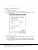
3. Check the status of indicators of the WF-122. If the RUN and LAN indicators turn
blinking green, the installation of the WF-122 is successful. Otherwise, please
refer to 4 FAQs.
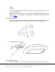
4.3.2 Cell Mounting
1. Mount the bigger kit first to a 9/16-inch and 15/16-inch T-bar of the cell, and drive
two screws into the T-bar to fix the kit. Push the smaller kit to the bigger kit.
Figure5 Mount cell kits
2. Install the WF-122 to the kit
Figure6 Mount the WF-122 to the cell
4.3.3 Wall Mounting
4. Drive two screws to fix the wall bracket to the wall. The dimension between two