
Specifications
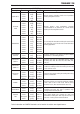
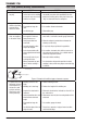

TRANSARC 170i
Manual 0-5281 4-5 BASIC WELDING GUIDE
If the travel is too fast, the bead will be narrow and strung out and may even be broken up into individual
globules. If the travel is too slow, the weld metal piles up and the bead will be too large.
Making Welded Joints
Having attained some skill in the handling of an electrode, you will be ready to go on to make up welded joints.
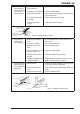
A. Butt Welds
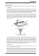
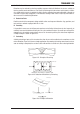
Set up two plates with their edges parallel, as shown in Figure 4-11, allowing 1.6mm to 2.4mm gap between
them and tack weld at both ends. This is to prevent contraction stresses from the cooling weld metal
pulling the plates out of alignment. Plates thicker than 6.0mm should have their mating edges bevelled to
form a 70º to 90º included angle. This allows full penetration of the weld metal to the root. Using a 3.2mm
Ferrocraft 21 electrode at 100 amps, deposit a run of weld metal on the bottom of the joint.
Do not weave the electrode, but maintain a steady rate of travel along the joint sufficient to produce a
well-formed bead. At first you may notice a tendency for undercut to form, but keeping the arc length
short, the angle of the electrode at about 20º from vertical, and the rate of travel not too fast, will help
eliminate this. The electrode needs to be moved along fast enough to prevent the slag pool from getting
ahead of the arc. To complete the joint in thin plate, turn the job over, clean the slag out of the back and
deposit a similar weld.
Art # A-07697_AB
Tack Weld
20°-30°
Electrode
Tack Weld
Figure 4-11: Butt Weld
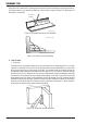
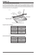
Art # A-07698
Figure 4-12: Weld Build up Sequence
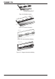
Heavy plate will require several runs to complete the joint. After completing the first run, chip the slag
out and clean the weld with a wire brush. It is important to do this to prevent slag being trapped by the
second run. Subsequent runs are then deposited using either a weave technique or single beads laid down
in the sequence shown in Figure 4-12. The width of weave should not be more than three times the core
wire diameter of the electrode. When the joint is completely filled, the back is either machined, ground or
gouged out to remove slag which may be trapped in the root, and to prepare a suitable joint for depositing
the backing run. If a backing bar is used, it is not usually necessary to remove this, since it serves a similar
purpose to the backing run in securing proper fusion at the root of the weld.
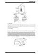
B. Fillet Welds
These are welds of approximately triangular cross-section made by depositing metal in the corner of two
faces meeting at right angles. Refer to Figure 4-4.
A piece of angle iron is a suitable specimen with which to begin, or two lengths of strip steel may be
tacked together at right angles. Using a 3.2mm Ferrocraft 21 electrode at 100 amps, position angle iron
with one leg horizontal and the other vertical. This is known as a horizontal-vertical (HV) fillet. Strike the
arc and immediately bring the electrode to a position perpendicular to the line of the fillet and about 45º
from the vertical. Some electrodes require to be sloped about 20º away from the perpendicular position