INSTRUCTION MANUAL Cilo C-102 AV-Receiver
02
Ta b l e of TABLE OF CONTENTS Table of contents OPERATION AND FUNCTIONS 03 IMPORTANT INSTRUCTIONS Important safety instructions 04 REMOTE CONTROL Installation of batteries Using the remote control Remote control functions contents 05 05 05 STANDBY Selection of input source Loudspeaker setup DSP, Mode, Mute and Bass Boost Selection of input signal Use of radio (tuner) Manual and automatic tuning Storing of radio stations Selection of station and RDS Selection of digital optical/coaxial inputs Select
Important safety instructions Congratulations on your new AV receiver. Please read this manual carefully to avoid malfunction and damage to the receiver and to ensure that the receiver will be a source of great pleasure to you for a very long time. Important safety instructions 1. Do not expose the receiver to direct sunlight, high humidity, dirt, heavy vibration or extreme temperatures. 2. Place the unit on a solid and plane surface. 3.
Remote control Installation of batteries Remove the cover as illustrated. Replace the cover. Insert two batteries of the type AAA/R03/UM4. Make sure that the terminals correspond to the symbols shown (see bottom). Do not mix new and old batteries, and do not use different types of batteries. If the remote control is not used for prolonged periods, remove the batteries from the remote control to prevent corrosion.
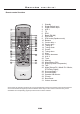
Remote control Remote control functions STANDBY SPEAKER 1. 2. 3. 4. 5. 6. 7. 8. 9. 10. 11. 12. 13. 14. 15. 16. 17. 18. 19. 20. 21. 22. 23. 24. 25. 26. 27. 28. 29. 30. 31.
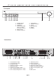
Front panel and connections Front panel VOLUME MODE STANDBY DSP HEADPHONE 1 2 INPUT TUNING SPEAKER A 3 4 5 BAND SPEAKER B 6 7 8 9 10 11 1. 2. 3. 4. Standby On/Off Standby LED Headphone Mode (Dolby Digital, DTS, PL II Movie, PL II Music, Stereo) 5. DSP Program 6. Speaker A selector 12 7. Input selector 8. Speaker B selector 9. Tuning 10. Band (FM/AM) 11. Display 12. Multijog Connections AV RECEIVER MODEL: Cilo C-102 ITEM NO.: 11098.
System setup The receiver shall not be connected to the mains supply before all other system connections have been made. Outline of audio/video connections The receiver is provided with two analogue and two digital audio/video inputs. A video or digital camera may e.g. be connected through the analogue audio/video inputs. The DVD player is connected through the digital inputs (optical or coaxial). The video signal is transmitted to the television set through the SCART connection.
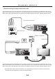
System setup Connection through analogue audio/video cable The audio/video jacks of the video camera are connected to the Cilo AV receiver through an audio/video cable. As you wish to see the film through your television set, the camera must also be connected to the television set. Use the SCART cable for this purpose (see illustration). For simplicity, the individual conductors have been marked by different colours.
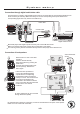
System setup Connection through digital audio/video cable The DVD player's coaxial or optical digital output must be connected with the corresponding digital input on the AV receiver (OPT/COAX). Make sure always to use the corresponding video input! Switch to the corresponding signal source by means of the INPUT key. Video cable Coaxial cable DVD-Player Optical cable Digital satelite receiver Most DVD players with digital outputs are factory-set at the PCM data format.
System setup Loudspeaker arrangement Before connecting the loudspeakers, these should be positioned correctly. Correct positioning is crucial to ensure optimal sound. The optimal location depends on the characteristics of the room and the walls. The illustration below shows an example of a speaker arrangement. 1. Listening position 2. Right front speaker 3. TV 4. Centre speaker 5. Left front speaker 6. Subwoofer 7. Right surround speaker 8.
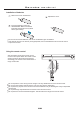
System setup Installation of AM antenna Install the AM antenna by mounting it on the fixing device (see illustration). Place the antenna in the position where the best signal is received, as far away from the system, the television set and the cables as possible. If the signal quality is not satisfactory, an outdoor antenna may be required. Connection of AM antenna Connect the two loop antenna wires to the inputs marked AM (see illustration).
System setup Installation and connection of FM antenna Connect the FM indoor antenna to the antenna connection marked FM 75. For this purpose, place the cable shoe on the pin in the middle of the connecting bush. Tune in to a station and place the antenna in the position where the best and clearest signal is received. If the signal quality is not satisfactory, an outdoor antenna may be required.
System setup Connection to the mains supply AV RECEIVER MODEL: Cilo C-102 ITEM NO.: 11098.01 POWER SOURCE: 220-240V~50/60Hz POWER CONSUMPTION: 200W MAX SERIAL NO.: FM - ANTENNA - AM R L SPEAKER A R L SPEAKER B FRONT SPEAKER OUTPUT CEN. OPT. VIDEO COAX VIDEO AUX 1 AUX 2 SUB SCART INPUT/OUTPUT SW SR SL SPEAKER OUTPUT Do not connect the receiver to the mains supply before all system connections have been made correctly.
Operation and functions Standby 1 Press the STANDBY key of the remote control to switch to standby mode. The display is switched off and all functions are reduced to a minimum. Thus the power consumption of the receiver is reduced to a minimum. In standby mode the receiver only responds to the STANDBY key of the remote control.
Operation and functions Loudspeaker setup 4 BAND RDS SPK MODE DSP MODE MEMORY MONO NIGHT CENTER BALANCE MODE 3 + SPEAKER DELAY 1 Press the VOL+ key to increase the volume, press the VOL- key to decrease the volume. 2 Turn Multijog to the right to increase the volume and to the left to decrease the volume 3 Press the BALANCE key repeatedly and then the VOL+/- keys to adjust the volume for all channels.
Operation and functions Selection of input signal Press the DIGITAL 1/DIGITAL 2/TUNER/AUX1/AUX2/TV key to select the corresponding input. Press the INPUT key on the front panel repeatedly to switch between the following inputs: DIGITAL 1/DIGITAL 2/TUNER/AUX1/AUX2/TV.
Operation and functions Manual and automatic tuning SPK MODE DSP MODE NIGHT TEST CENTER BALANCE MODE REAR + DELAY SPEAKER Press the TUNING key to switch between "TUN STEP" (manual) and "TUN SCAN" (automatic). Press either the TUNING UP key or the TUNING DOWN key to start searching. + DELAY - TUNING + MANUAL PR - The search function may also be activated directly from the front panel. Press the TUNING key and start searching by means of the Multijog.
Operation and functions Selection of digital optical / coaxial inputs Press the DIGITAL 1/DIGITAL 2 keys to activate the digital inputs. Check that the Setup (digital output) of the peripheral devices are set at RAW and bitstream respectively. Depending on the size of the room, the speakers may be configured through CENTRE DELAY and SURROUND DELAY. Selection is also possible through the front panel by pressing the INPUT key repeatedly.
Te c h n i c a l Frequency respons S/N THD Digital inputs Analog input Video input Power Power consumption Music power Measures Weight data 20-20.000Hz >105dB <0.1% Optical and coaxial RCA RCA 220-240V~50/60Hz 200W 5 x 60W + 1 x 100W 430 x 68 x 330mm ca. 6kg. We reserve the right to change the technical data and design without notice as a result of further development.
Tr o u b l e s h o o t i n g PROBLEM Nothing happens, all displays are dark. Only the POWER LED is alight. The system does not respond to the remote control. Systemet leverer ingen lyd. No sound on the digital input. CAUSE/REMEDY The mains plug has not been inserted (don't laugh check it out!) There is no mains voltage. Check that the socket used carries current (e.g. by means of a lamp). The receiver is not switched on. The receiver is in standby mode. Press the STANDBY key on the remote control.
Item No.