
User's Manual


Installation Procedure
ISLC35
00
-
C
Page 3
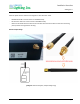
2. Electrical Connections
Field wiring to be done using appropriate connectors. Example from ‘WAGO 221’ series Splicing Connector (UL file
‘ZMVV.E69654) OR any other equivalent.
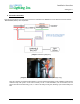
[Image-4: Field wiring diagram]
[Image-5: Field wiring through WAGO terminals, example image only]
Once the Controller is installed and luminaire is powered ON then depending on the scheduled configuration
condition Lamp will operate. If unit wired correctly, for the 1
st
time installation / lab environment, one can
observe the initial commissioning cycle, i.e. and see the Lamp turning ON, dimming cycle and then lamp turn
OFF.