Notices PC Worth makes no warranty of any kind with regard to this publication, including, but not limited to, the implied warranty of merchantability and fitness for any particular purpose. PC Worth shall not be liable for errors contained herein or for incidental consequential damages in connection with the furnishing, performance, or use of this publication. This publication contains proprietary information that is protected by copyright. All rights are reserved.
Table of Contents International Edition, Rev. B Getting Started ............................................................................... 1 Getting Familiar with MBC6890 Cordless Imager.................... 2 Decide the Radio Link Mode ................................................... 4 Preparations Before Using...................................................... 5 Using MBC6890 Cordless Imager ................................................. 7 Using MBC6890 with DB100 Smart Cradle...............
Getting Started Thank you for choosing MBC6890 series Bluetooth Cordless Linear Imager. The MBC6890 series cordless imagers are designed with remarkable optical architecture and innovative functionality. By incorporating Bluetooth£ 1.2 wireless technology which operates on the 2.4 GHz ISM band, the MBC6890 series is compatible with most popular Bluetooth-enabled devices, such as PCs, laptops and PDAs, and so on.
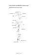
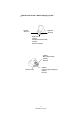
Getting Familiar with MBC6890 Cordless Imager x MBC6890 Bluetooth Cordless Imager Scan Window Reset Button Trigger Unlock Hole Imager LED Buzzer Hand Strip Hole Battery Tank Battery Cover End Cap Battery Cover Lock Internal Connector 2 MBC6890 User’s Guide
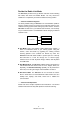
x DB100 Smart Cradle / DA100 Charging Cradle Left LED - Reserved Right LED - Reserved Middle LED [ DB100 ] Connection Status Indication [ DA100 ] Power On Indication [ DB100 ] Multi Function Button [ DA100 ] Reserved [ DB100 ] Universal Legacy Output Port DC Power Jack [ DA100 ] Reserved 3 MBC6890 User’s Guide
Decide the Radio Link Mode The MBC6890 provides three (3) different radio link modes including Pair Mode, SPP Slave and Master Modes. You may choose the suitable one to implement your desired cordless scanning solution. …… Note for Installation Engineer The factory default setting of MBC6890 is in “Uninstall State” (Radio is inactive.). Please choose one of the three (3) radio link modes for your cordless scanning system before making any further actions.
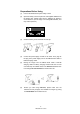
Preparations Before Using (1) Have a remote Bluetooth system ready to work. (2) Open the battery cover then place the rechargeable batteries into the battery tank. Please make sure the batteries are placed in correct direction. (Do not charge non-rechargeable batteries, as it may cause explosion.) (3) Close the battery cover and insert the end cap. (4) Connect the power supply unit with an AC outlet. Then, plug the DC plug of the power supply unit into the DB100 smart cradle or DA100 charging cradle.
6 MBC6890 User’s Guide
Using MBC6890 Cordless Imager The MBC6890 cordless imager has to establish communication with a host system for data transmission. There are several ways for connecting MBC6890 to the host system: By using with the DB100 smart cradle, through one of legacy output interfaces such as PS/2 keyboard wedge, RS232 serial interface, USB keyboard interface and USB serial interface and so on. By means of Bluetooth wireless communication via SPP master service or SPP slave service.
Using MBC6890 with DB100 Smart Cradle The MBC6890 works with DB100 smart cradle to perform just as it is directly wire-connected to a host PC through one of legacy interfaces such as PS/2 keyboard wedge, RS232 serial, USB keyboard and USB serial. The “Pair Mode” scanning system is the most convenient “Cable Replacement” solution, if there is no Bluetooth device in your existing system.
The Installation Procedure Please refer to following procedures for connecting MBC6890 to a host system by using with DB100 smart cradle: (1) Make sure that batteries are fully charged and placed into MBC6890. You may refer to the Section “Preparations Before Using” for details. (2) Power off the host system. (3) Connect the desired interface cable (such as: PS/2 keyboard wedge interface cable) with DB100 smart cradle and host PC. You will hear a ‘click’ when the connection is made.
(9) Scan “Pair Mode” barcode command. The imager gives 2 short beeps, and imager LED gives red blinks. Pair Mode Command After scanning the “Pair Mode” barcode command, the imager will enter into “Sleep State”, if the imager is not placed on the cradle within 10 seconds. You can press the trigger switch to revert it to pairing process. If you want to switch it back to “Uninstall State”, please press and hold the trigger switch for 2 seconds. (10) Place the imager on the cradle within 10 seconds.
x Host Interface Quickset Command PC/AT, PS/2 Keyboard Wedge Quick Set Command Keyboard Replacement Quick Set Command RS-232 Serial Interface Quick Set Command USB Keyboard Interface Quick Set Command USB Serial Interface Quick Set Command If the USB serial interface is selected, you have to install the USB virtual COM driver in your host system before using the imager. You may obtain the software driver from your supplier or download it from our web site.
Enable Out-of-Range Scanning Under normal mode (default setting), when the radio link between the MBC6890 and the host system is built, the MBC6890 transmits each scanned data right after scanning the bar code label. However, the MBC6890 can not scan any bar code data while losing its connection with the remote host system due to out of range. You might enable the option of “Out-of-range Scanning” to have MBC6890 stored the scanned data even the imager is out of range.
Activate Batch Mode You can activate batch mode to have MBC6890 stored scanned data without building the connection with a remote host system. To enable this function, please scan “Enter Batch Mode” quick set command. When a bar code is saved successfully, a good read beep sounds and the LED flashes green. When the memory buffer is full, the MBC6890 will give a long beep and the LED flashes red.
Using MBC6890 via Bluetooth SPP Service Bluetooth wireless technology works on global RF standards, which operates on the 2.4 GHz ISM band. This enables wireless connectivity between the remote Bluetooth devices and the host computer built-in Bluetooth radio, such as PCs, laptops and PDAs, etc. Usually, all actions between a program installed on your computer and a remote Bluetooth device are carried out by the Bluetooth services. A Bluetooth device can offer one or more services.
Establish SPP Master Connection While configuring the MBC6890 to be used in SPP Master mode, the Imager will initiate the connection to the remote Bluetooth host system. The special-designed Auto Reconnecting feature is provided by MBC6890 under this mode. If the radio link is lost, the automatic radio re-build process will be activated immediately. It’s no need for user to re-build the radio connection manually.
(6) Scan the “SPP Master Mode” barcode command, the imager gives 2 short beeps and imager LED gives red blinks. SPP Master Mode Quick Set Command After scanning the “SPP Master Mode” barcode command, the imager will enter “Sleep State”, if the radio link is not built within 1 minute. You can press the trigger switch to revert it to SPP Master process. If you want to switch it back to “Uninstall State”, please press and hold the trigger switch for 2 seconds.
Enable Out-of-Range Scanning Under normal mode (default setting), when the radio link between the MBC6890 and the host system is built, the MBC6890 transmits each scanned data right after scanning the bar code label. However, the MBC6890 can not scan any bar code data while losing its connection with the remote host system due to out of range. You might enable the option of “Out-of-range Scanning” to have MBC6890 stored the scanned data even the imager is out of range.
Activate Batch Mode You can activate batch mode to have MBC6890 stored scanned data without building the connection with a remote host system. To enable this function, please scan “Enter Batch Mode” quick set command. When a bar code is saved successfully, a good read beep sounds and the LED flashes green. When the memory buffer is full, the MBC6890 will give a long beep and the LED flashes red.
Establish SPP Slave Connection While configuring the MBC6890 to be used in SPP Slave mode, the imager will only wait for the connection request issued by the remote Bluetooth master system to establish the radio link. Once the pre-built radio link is lost, user has to re-build the radio link manually. Generally speaking, Widcomm provides complete Windowś based Bluetooth software and its stacks have been broadly adopted by the Bluetooth industry.
(5) Scan the “SPP Slave Mode” barcode command, the imager gives 2 short beeps and imager LED gives red blinks. SPP Slave Mode Quick Set Command Your imager is now ready to be discovered by a remote Bluetooth master device. After scanning the “SPP Slave Mode” barcode command, the imager will enter “Sleep State”, if the radio link is not built within 1 minute. You can press the trigger switch to revert it to SPP Slave process.
Enable Out-of-Range Scanning Under normal mode (default setting), when the radio link between the MBC6890 and the host system is built, the MBC6890 transmits each scanned data right after scanning the bar code label. However, the MBC6890 can not scan any bar code data while losing its connection with the remote host system due to out of range. You might enable the option of “Out-of-range Scanning” to have MBC6890 stored the scanned data even the imager is out of range.
Activate Batch Mode You can activate batch mode to have MBC6890 stored scanned data without building the connection with a remote host system. To enable this function, please scan “Enter Batch Mode” quick set command. When a bar code is saved successfully, a good read beep sounds and the LED flashes green. When the memory buffer is full, the MBC6890 will give a long beep and the LED flashes red.
Operations and Indications The MBC6890 has two indicators, LED and buzzer. They will provide various indications depending on the actual operating conditions and states.
Useful Tips for Field Operation Please refer following four useful tips for your field operation : 4 descending-tone beeps When you heard the special 4 descending-tone beeps, it means the imager has lost the radio link already. This condition mostly happens when you go out of the radio covering range. And the imager LED will give red blinks at regular interval to indicate Radio Disconnected state.
MBC6890 Major States During Operation Once the scanning system is properly set up, MBC6890 will always be under one of the following Operational States: Indications State & Actions LED Beeper 1. Radio Uninstall State Æ Radio link not installed Æ Install the radio link alternating red & green blinks 2. Radio Connected State Æ Radio link installed already, the imager is connected to a remote Bluetooth device Æ Ready to scan a regular barcode 1 green blink at regular interval 3.
MBC6890 Indications Indications No LED Descriptions Beeper “Sleep State”, or “Batteries no power”, or No batteries inside 1 “Under Configuration” 2 steady red “Radio Uninstall State” 3 4 alternating red & green blinks “Radio Connected” (Ready to scan barcode) 1 green blink at regular interval “Radio Disconnected” 5 1 red blink at regular interval “Battery power low” 6 1 red blink at regular interval 1 beep at regular interval “Power extremely low” 7 8 red blinks 8 beeps Time out warning 8
MBC6890 Indications (Continued) Indications No LED Descriptions Beeper Configuration fail 10 3 red blinks 3 beeps “Good Read” beep 11 12 1 green blink 1 green blink 1 good read beep 1 ACK beep Receiving ACK signal from smart cradle or host PC Power on indication 13 1 green blink power-on reset beeps Radio connection built 14 1 green blink 4 beeps in ascending tone Radio connection lost 15 1 red blink 4 beeps in descending tone Cradle paging Imager 16 10 red blinks page beeps Imager
Cradle Indications Right LED : Reserved Left LED : Reserved Middle LED : DB100 - Connection status indication DA100 - Power on Indication Middle LED of DB100 Smart Cradle Indications No LED Descriptions Beeper “Sleep State”, or “Battery no power”, or No battery inside 1 Steady red “Under Configuration” 2 Steady green Configuration successful 3 Steady green “Radio Uninstall State” 4 red & green blinks “Radio Connected” 5 Steady green “Radio Disconnected” 6 Steady red Radio connection buil
Configure MBC6890 Cordless Imager The FuzzyScan bar code commands are specially designed for field programming convenience. All MBC6890 series cordless linear imagers can take this way to make detailed configuration. Before configuring your imager, please understand the command structure and programming procedures in advance. The bar code commands include System Command, Family Code and Option Code for programming purpose.
Programming Procedures As you scan the bar code command to select the desired parameters, all the final selected configurations will be stored in the FuzzyScan’s internal non-volatile memory. If you power off the unit, the imager retains all programming options. You need not re-program the FuzzyScan if you want to keep the existing configurations for the next power on. The programming procedures of FuzzyScan are designed as simple as possible for ease of setting.
Host Interface Selection Command Host Interface Selection P.C.
Operation Control 1Command P.C.
Symbology Reading Control User Defined Symbol ID Command Symbol ID - 1 character - nd P.C.
Codabar & NW-7 Setting Command Codabar Setting P.C.
Code 25 & German Post Setting Command Code 25 Setting P.C.
MSI/Plessey Setting Command P.C.
Keyboard Interface Control Command Language Setting Record Suffix P.C.
Serial Interface Control Command P.C. Parameter Selection Option SS SS Disable STX/ETX transmission Enable STX/ETX transmission SS SS SS SS SS None CR (0DH) LF (0AH) CRLF (0D0AH) SS SS SS SS None (free running mode) RTS/CTS (hardware handshaking) ACK/NAK (software handshaking) Xon/Xoff (software handshaking) 0 1 2 3 SS SS Disable Enable 0 1 SS MS None 1-99 msec. FIN (2 digits) SS MS None 1-99 (X 5) msec. FIN (2 digits) SS SS SS SS SS 38.4K BPS 19.
Wand Emulation Control Command P.C. Parameter Selection Option SS SS High level (5Vdc) on Bar (low level on Space) Low level (0Vdc) on Bar (high level on Space) 0 1 SS SS High Level (5 Vdc) Low Level (0 Vdc) 0 1 SS SS SS SS 10 mseconds 15 mseconds 20 mseconds 25 mseconds 30 mseconds 50 mseconds 100 mseconds 0 1 2 3 4 5 6 SS SS Extremely Short Short Medium Long 0 1 2 3 Narrow/Wide Ratio SS SS SS 1:2 1:2.
Condensed DataWizard DataWizard is a powerful, artificial intelligence based data editing expert system provided specially for the FuzzyScan family bar code readers. Through DataWizard, you can process the scanned data prior to the transmissions in many ways, such as: Insert, Delete, Match, Verify, Substitute, Reorganize, and Repeat Transmission. It will help you to transmit the scanned data to any specific format without software modifications. Please refer to below for details.
Preamble, Postamble, Data Length Setting Command P.C. Parameter Selection Option SS MS None 1-15 characters FIN [00-7F], [FIN] SS MS None 1-15 characters FIN [00-7F], [FIN] SS SS Disable Enable 2-digits data length transmission If data length exceeds 99, 3-digit data length will be transmitted Preamble Postamble Data Length Transmission 0 1 Data Formatter Setting Command P.C.
Data Changer Setting Option nd Command P.C. Parameter Selection 2 Option Changer Control SS MS MS Disable Select one bar code symbology Select all bar code symbologies FIN (2 digits) 00 SS DS Disable Enable FIN (2 digits) [00-7F] SS DS Disable Enable FIN (2 digits) [00-7F] SS DS Disable Enable FIN (2 digits) [00-7F] 1st Substitute 2nd Substitute 3rd Substitute Data Organizer Setting nd Command P.C.
Select a Bar Code Symbology You can select one or all types of bar code symbologies to use Condensed DataWizard for advanced transmission arrangement. If you scan “00” to select all types, the MBC6890 will arrange all incoming data to meet your pre-defined format. If you want to select only one type bar code, please select one of the option code listed below.
Programming Procedure μData Verifierν Scan “Program” to enter the programming mode. Scan “Verifier Control” and set bar code symbology to “08” (Interleaved 2 of 5). Scan “Identified Data Length” and set the length to “16”. st Scan “1 Identified Character” and set the Identified position to “00”, then set the identified character to “39” (Hex Code of 9). μData Formatterν Scan “Formatter Control” and set bar code symbology to “08”.
Appendix This appendix provides most useful supplementary information for following topics: Keyboard Function Code Table HEX/ASC Input Shortcut Barcode System Commands Option Codes and System Commands 45 MBC6890 User’s Guide
Keyboard Function Code Table No. ANSI ASCII 00 NUL 00H 01 SOH 02 STX 03 ETX 04 Key Function No.
ASCII Input Shortcut To set the user definable configurations of MBC6890 via programming menu, the MBC6890 may ask you to scan your desired ASCII value in HEX form. You have to refer to the “HEX/ASCII Reference Table” for details. Example : If you want the scanned data output leading with a Dollar Sign, you have to set the “Preamble” to “$”. The configuration procedure is listed below for reference. Scan PROGRAM command from “Option Codes and System Commands” to enter programming mode.
Barcode System Commands PROGRAM END (EXIT) System Information List Factory Default Setting PowerTool Host Link Enter Batch Mode Exit Batch Mode 48 MBC6890 User’s Guide
Barcode System Commands Radio Link Setting Host Interface Setting PC/AT, PS/2 Keyboard Wedge Quick Set Command Uninstall Keyboard Replacement Quick Set Command Pair Mode RS232 Serial Interface Quick Set Command SPP Slave Mode USB Keyboard Interface Quick Set Command SPP Master Mode USB Serial Interface Quick Set Command Paging Command Radio Off Sleep Command 49 MBC6890 User’s Guide
Barcode Option Codes 0 A 1 B 2 C 3 D 4 E 5 F 6 PROGRAM 7 FIN (Finish) 8 END (Exit) 9 50 MBC6890 User’s Guide
www.cino.com.