
Specifications

CINTERION
®
BGS12 Hardware Interface Description
Contents
32 of 109
Page
BGS12 HID_V00.915
Confidential / Released
2019
-
01
-
07
Abbreviations used in above Table 7:
L = Low level OD = Open Drain
H =High level PD = Pull Down
L/H = Low or High level PU = Pull Up
T = Tristate
I = Input
O = Output
IO=Input or Output
3.3.4 Turn off BGS12
To switch the module off the following procedures may be used:
•
Software controlled shutdown procedure: See Section 3.3.4.1.
Software controlled by sending the AT^SMSO command over the serial application
interface.
•
Automatic shutdown of BGS12 due to safety precautions: See Section 3.3.5
•
Fast shutdown (Hardware line): See Section 3.19
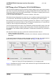
3.3.4.1
Switch off BGS12 Using AT Command
The best and safest approach to powering down BGS12 is to issue the AT^SMSO com-
mand. This procedure lets BGS12 log off from the network and allows the software to enter
into a secure state and safe data before disconnecting the power supply. The mode is re-
ferred to as Power Down mode. In this mode, only the RTC stays active.
Before switching off the device sends the following response:
^SMSO: MS OFF
OK
^SHUTDOWN
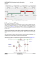
After sending AT^SMSO do not enter any other AT commands. There are two ways to verify
when the module turns off:
•
Wait for the URC “^SHUTDOWN”. It indicates that data have been stored non-volatile and
the module turns off in less than 1 second.
•
Also, you can monitor the VDIG pad. The low state of this pad definitely indicates that the
module is switched off.
Be sure not to disconnect the operating voltage V
BATT+
before the URC “^SHUTDOWN” has
been issued and the VDIG pads have gone low. Otherwise you run the risk of losing data.
While BGS12 is in Power Down mode the application interface is switched off and must not
be fed from any other voltage source. Therefore, your application must be designed to avoid
any current flow into any digital pads of the application interface.