
Specifications
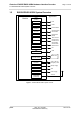
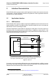
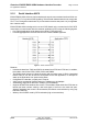
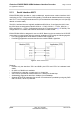
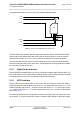
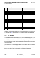
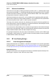
Table Of Contents

Cinterion
®
EHS5-E/EHS5-USR4 Hardware Interface Overview
2.1 Application Interface
28
ehs5_hio_v04.000 2019-01-16
Confidential / Preliminary
Page 14 of 46
2.1.3 Serial Interface ASC1
EHS5-E/EHS5-USR4 provides a 4-wire unbalanced, asynchronous modem interface ASC1
conforming to ITU-T V.24 protocol DCE signalling. The electrical characteristics do not comply
with ITU-T V.28. The significant levels are 0V (for low data bit or active state) and 1.8V (for high
data bit or inactive state).
The ASC1 interface lines are originally available as GPIO lines. If configured as ASC1 lines,
the GPIO lines are assigned as follows: GPIO16 --> RXD1, GPIO17 --> TXD1, GPIO18 -->
RTS1 and GPIO19 --> CTS1. Configuration is done by AT command (see [1]: AT^SCFG). The
configuration is non-volatile and becomes active after a module restart.
EHS5-E/EHS5-USR4 is designed for use as a DCE. Based on the conventions for DCE-DTE
connections it communicates with the customer application (DTE) using the following signals:
• Port TXD @ application sends data to module’s TXD1 signal line
• Port RXD @ application receives data from the module’s RXD1 signal line
Figure 4: Serial interface ASC1
Features
• Includes only the data lines TXD1 and RXD1 plus RTS1 and CTS1 for hardware hand-
shake.
• On ASC1 no RING line is available.
• Configured for 8 data bits, no parity and 1 or 2 stop bits.
• ASC1 can be operated at fixed bit rates from 1,200 bps to 921600 bps.
• Autobauding supports bit rates from 1200bps up to 230400bps.
• Supports RTS1/CTS1 hardware flow control. Communication is possible by using only RXD
and TXD lines, if RTS1 is pulled low.